Advertisement
Available languages
Available languages
Quick Links
Montage- und
Gebrauchsanweisung
Installation and
Operating Instructions
Instructions d'installation
et d'utilisation
Luft/Wasser-
Wärmepumpe für
Innenaufstellung
Bestell-Nr. / Order no. / N
Air-to-Water
Heat Pump for
Indoor Installation
o
de commande : 452157.66.73
WPL 60I
Pompe à chaleur
air-eau pour
installation
intérieure
FD 8607
Advertisement
Chapters

Subscribe to Our Youtube Channel
Related Manuals for Buderus WPL 60I


Summary of Contents for Buderus WPL 60I
- Page 1 Montage- und Gebrauchsanweisung Installation and Operating Instructions Instructions d’installation et d’utilisation WPL 60I Luft/Wasser- Air-to-Water Pompe à chaleur Wärmepumpe für Heat Pump for air-eau pour Innenaufstellung Indoor Installation installation intérieure Bestell-Nr. / Order no. / N de commande : 452157.66.73...
-
Page 3: Table Of Contents
Inhaltsverzeichnis Bitte sofort lesen .......................... D-2 1.1 Wichtige Hinweise ..........................D-2 1.2 Gesetzliche Vorschriften und Richtlinien ....................D-2 1.3 Energiesparende Handhabung der Wärmepumpe .................D-2 Verwendungszweck der Wärmepumpe ..................D-3 2.1 Anwendungsbereich ..........................D-3 2.2 Arbeitsweise ............................D-3 Lieferumfang..........................D-3 3.1 Grundgerät..............................D-3 3.2 Schaltkasten ............................D-4 3.3 Beipack ..............................D-4 Transport............................ -
Page 4: Bitte Sofort Lesen
Bitte sofort lesen 1.2 Gesetzliche Vorschriften und Richtlinien 1.1 Wichtige Hinweise Bei der Konstruktion und Ausführung der Wärmepumpe wurden alle entsprechenden EG-Richtlinien, DIN- und VDE-Vorschriften ACHTUNG! eingehalten (siehe CE-Konformitätserklärung). Das Gerät ist nicht für Frequenzumrichterbetrieb geeignet. Beim elektrischen Anschluss der Wärmepumpe sind die entspre- chenden VDE-, EN- und IEC-Normen einzuhalten. -
Page 5: Verwendungszweck Der Wärmepumpe
Verwendungszweck der Lieferumfang Wärmepumpe 3.1 Grundgerät 2.1 Anwendungsbereich Die Wärmepumpe wird in Kompaktbauweise geliefert und enthält bereits wichtige Baugruppen des Heizungskreislaufs: Die Luft/Wasser-Wärmepumpe kann in vorhandenen oder neu Ausdehnungsgefäß zu errichtenden Heizungsanlagen eingesetzt werden. Heizungsumwälzpumpe Die Wärmepumpe ist ausschließlich für die Erwärmung von Überstromventil und Sicherheitsbaugruppe (Überdruckven- Heiz- und Brauchwasser konzipiert! til, Manometer) -
Page 6: Schaltkasten
Transport 3.2 Schaltkasten Der Schaltkasten befindet sich in der Wärmepumpe. Er ist nach ACHTUNG! Abnahme der unteren Frontabdeckung zugänglich. Die Wärmepumpe darf beim Transport nur bis zu einer Neigung von 45° Im Schaltkasten befinden sich die Netzanschlussklemmen, (in jeder Richtung) gekippt werden. sowie die Leistungsschütze, die Sanftanlauf-Einheit und der Wärmepumpenregler. -
Page 7: Aufstellung
Aufstellung Montage 5.1 Allgemein 6.1 Allgemein Die Wärmepumpe ist für die Eckaufstellung konzipiert. In Verbin- An der Wärmepumpe sind folgende Anschlüsse herzustellen: dung mit einem Luftkanal (als Zubehör erhältlich) an der Zu-/Abluft Ausblasseite sind auch andere Aufstellungen möglich. Vor-/Rückläufe der Heizungsanlage Das Gerät ist grundsätzlich in Innenräumen auf einer ebenen, Kondensatablauf glatten und waagrechten Fläche aufzustellen. -
Page 8: Heizungsseitiger Anschluss
6.3 Heizungsseitiger Anschluss Zum Anschluss an das Heizsystem liegen der Wärmepumpe fle- xible Schlauchanschlussstücke und Doppelnippel mit 1" Außen- gewinde bei. Dadurch ist wahlweise eine gewindedichtende oder flachdichtende Verbindung zum Heizsystem möglich. Ist keine Warmwassererwärmung durch die Wärmepumpe vor- gesehen, so ist der Warmwasserausgang durch den beiliegen- den Dichtstopfen dauerhaft abzudichten. -
Page 9: Elektrischer Anschluss
Inbetriebnahme 6.4 Elektrischer Anschluss Die Leistungsversorgung und Steuerspannung werden über die 7.1 Allgemein vormontierten (Last: 4-adrig, Steuerung: 3-adrig) Leitungen zu- geführt. Um eine ordnungsgemäße Inbetriebnahme zu gewährleisten, In der Leistungsversorgung ist eine allpolige Abschaltung mit sollte diese von einem vom Werk autorisierten Kundendienst mindestens 3 mm Kontaktöffnungsabstand (z.B. -
Page 10: Reinigung / Pflege
Reinigung / Pflege Wärmequellen- max. Temperaturspreizung temperatur zwischen Heizungsvor- und 8.1 Pflege Rücklauf -20 °C -15 °C Vermeiden Sie zum Schutz des Lackes das Anlehnen und Able- -14 °C -10 °C gen von Gegenständen am und auf dem Gerät. Die Außenteile -9 °C -5 °C der Wärmepumpe können mit einem feuchten Tuch und mit han-... -
Page 11: Reinigung Luftseite
Störungen / Fehlersuche 8.3 Reinigung Luftseite Luftkanäle, Verdampfer, Lüfter und Kondensatablauf sind vor der Diese Wärmepumpe ist ein Qualitätsprodukt und sollte störungs- Heizperiode von Verunreinigungen (Blätter, Zweige usw.) zu rei- und wartungsfrei arbeiten. Tritt dennoch einmal eine Störung auf, nigen. Dazu ist die Wärmepumpe an der linken Seite und Front- wird diese im Display des Wärmepumpenmanagers angezeigt. -
Page 12: Geräteinformation
11 Geräteinformation Geräteinformation Typ- und Verkaufsbezeichnung WPL 60I Bauform Ausführung Kompakt Schutzart nach EN 60 529 für Kompaktgerät bzw. Heizteil IP 20 Aufstellungsort Innen Leistungsangaben Temperatur-Betriebseinsatzgrenzen: bis 55 / ab 18 Heizwasser-Vorlauf / -Rücklauf °C / °C Luft °C -20 bis +35... -
Page 13: Garantieurkunde
örtlichen Versorgungsunternehmen oder unsere Montage- und Gebrauchsanweisung sowie die in den Projektie- Österreich: rungsunterlagen enthaltenen Hinweise oder Einbindungssche- Buderus Austria Heiztechnik Gesellsch.mbH men nicht beachtet worden sind oder wenn unser funktionsnot- Rennbahnweg 65 wendiges Zubehör nicht eingesetzt wurde. Durch etwa seitens A-1220 Wien des Endabnehmers oder Dritter unsachgemäß... - Page 14 Table of contents Please Read Immediately......................E-2 1.1 Important Information:..........................E-2 1.2 Legal Regulations and Directives ......................E-2 1.3 Energy-Efficient Use of the Heat Pump ....................E-2 Purpose of the Heat Pump ......................E-3 2.1 Application ..............................E-3 2.2 Operating Principle ..........................E-3 Scope of Delivery.......................... E-3 3.1 Basic Device ............................E-3 3.2 Switch Box ..............................E-4 3.3 Accessories Pack............................E-4...
-
Page 15: Please Read Immediately
Please Read 1.2 Legal Regulations and Immediately Directives The construction and design of the heat pump complies with all relevant EU directives, DIN/VDE regulations (see CE declaration 1.1 Important Information: of conformity). When connecting the heat pump to the power supply, the rele- ATTENTION! vant VDE, EN and IEC standards are to be fulfilled. -
Page 16: Purpose Of The Heat Pump
Purpose of the Heat Scope of Delivery Pump 3.1 Basic Device 2.1 Application The compact heat pump is supplied complete with all of the im- portant components of the heating circulation system: The air-to-water heat pump is designed for use in existing or Expansion vessel newly built heating systems. -
Page 17: Switch Box
Transport 3.2 Switch Box The switch box is located in the heat pump. It can be accessed ATTENTION! by removing the lower front cover. When transporting the heat pump, ensure that it is not tilted more than The switch box contains the supply connection terminals, as well 45°... -
Page 18: Set-Up
Set-UP Installation 5.1 General Information 6.1 General Information The heat pump is designed for installation in a corner. Other in- The following connections need to be established on the heat stallation locations are also possible in combination with an air pump: duct (available as an accessory) on the air outlet side. -
Page 19: Heating System Connection
An overflow valve is installed in the device for systems in which the heating water flow can be shut off via the radiator or thermo- stat valves. This ensures a minimum heating water flow rate through the heat pump and helps to avoid faults. Once the heating system has been installed, it must be filled, de- aerated and pressure-tested. -
Page 20: Start-Up
Start-UP Heat source Max. temperature spread temperature between heating flow and return 7.1 General Information flow From -20 °C -15 °C To ensure that start-up is performed correctly, it should only be -14 °C -10 °C carried out by an after-sales service technician authorised by the -9 °C -5 °C manufacturer. -
Page 21: Maintenance / Cleaning
Maintenance / Cleaning 8.3 Cleaning the Air System Air ducts, evaporator, ventilator and condensate outflow should 8.1 Maintenance be cleaned of contamination (leaves, twigs, etc.) before the heat- ing period. Do this by opening the left and front sides of the heat To protect the paintwork, avoid leaning or putting objects on the pump. -
Page 22: Device Information
11 Device Information Device Information Type and order code WPL 60I Design Model Compact Degree of protection according to EN 60 529 for compact devices IP20 and heating components Installation location Indoors Performance data Operating temperature limits: Up to 55 / above 18 Heating water flow/return flow °C / °C... - Page 23 Table des matières A lire immédiatement !........................F-2 1.1 Importantes informations ........................F-2 1.2 Dispositions légales et directives......................F-2 1.3 Utilisation de la pompe à chaleur pour économiser de l'énergie ............F-2 Utilisation de la pompe à chaleur ....................F-3 2.1 Domaine d’utilisation..........................
-
Page 24: Lire Immédiatement
A lire immédiatement ! 1.2 Dispositions légales et directives 1.1 Importantes informations Lors de la construction et de la réalisation de la pompe à chaleur, toutes les normes CE et prescriptions DIN et VDE concernées ATTENTION ! ont été respectées (voir déclaration de conformité CE). L’appareil ne convient pas au mode convertisseur de fréquence. -
Page 25: Utilisation De La Pompe À Chaleur
Utilisation de la pompe Fournitures à chaleur 3.1 Appareil de base 2.1 Domaine d’utilisation La pompe à chaleur est livrée sous forme compacte et contient déjà d´importants modules du circuit de chauffage : La pompe à chaleur eau glycolée-eau peut être utilisée dans les Vase d´expansion installations de chauffage déjà... -
Page 26: Boîtier Électrique
Transport 3.2 Boîtier électrique Le boîtier électrique est monté dans la pompe à chaleur. Pour y ATTENTION ! accéder, il suffit de retirer l'habillage inférieur de la façade. Lors du transport, l’angle d’inclinaison de la pompe à chaleur ne doit pas Dans le boîtier électrique se trouvent les bornes de connexion au dépasser 45°... -
Page 27: Emplacement De Montage
Emplacement de 5.2 Ecoulement des condensats montage Les condensats se formant en cours de fonctionnement doivent être évacués sans risque de gel. Pour garantir un écoulement ir- réprochable, la pompe à chaleur doit se trouver à l’horizontale. 5.1 Remarques d’ordre général Le tuyau à... -
Page 28: Installation
Installation 6.1 Remarques d’ordre général Les raccordements suivants doivent être réalisés sur la pompe à chaleur : Aspiration/évacuation d’air Circuits départ et retour de l’installation de chauffage Ecoulement des condensats Ecoulement des vannes de surpression Alimentation électrique 6.2 Prise d’air ATTENTION ! Les canaux d’aspiration et d’évacuation d'air ne doivent être ni rétrécis, ni obturés. -
Page 29: Branchement Côté Installation De Chauffage
6.3 Branchement côté installation 6.4 Branchements électriques de chauffage L’alimentation en puissance et la tension de commande sont amenées via les conducteurs déjà montés (charge : 4 fils, com- Pour le raccordement au système de chauffage, la pompe à cha- mande : 3 fils). -
Page 30: Mise En Service
Mise en service à chaleur. La cartouche chauffante doit être désactivée pour des installations mono-énergétiques. 7.1 Remarques d’ordre général Température Différence de température max. de départ entre circuits départ et retour du Pour garantir une mise en service en règle, cette dernière doit chauffage à... -
Page 31: Nettoyage / Entretien
Nettoyage / entretien pression doit être ouvert pour permettre l’entrée d’air dans le ré- servoir tampon. 8.1 Entretien 8.3 Nettoyage côté air Afin de protéger la laque, il faut éviter d’appuyer ou de déposer Les conduits d’air, l’évaporateur, l’aérateur et l’écoulement des des objets sur l’appareil. -
Page 32: Informations Sur Les Appareils
11 Informations sur les appareils Informations sur les appareils Désignation technique et commerciale WPL 60I Forme Version compacte Type de protection selon EN 60 529 pour app. compact ou élt. de chauffe IP 20 Emplacement en intérieur Indications de puissance Température - limites d’exploitation :... - Page 33 Anhang / Appendix / Annexes Maßbilder / Dimension Drawings / Schémas cotés..............A-II 1.1 Wärmepumpe / Heat pump / Pompe à chaleur ..................A-II 1.2 Einbaumaße / Installation Dimensions / Cotes de montage ..............A-III Diagramme / Diagrams / Diagrammes..................A-IV 2.1 Kennlinien / Characteristic Curves / Courbes caractéristiques..............A-IV Stromlaufpläne / Circuit Diagrams / Schémas électriques............
-
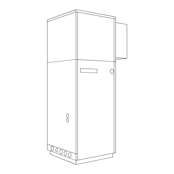
Page 34: Maßbilder / Dimension Drawings / Schémas Cotés
1 Maßbilder / Dimension Drawings / Schémas cotés 1.1 Wärmepumpe / Heat pump / Pompe à chaleur A-II... -
Page 35: Einbaumaße / Installation Dimensions / Cotes De Montage
1.2 Einbaumaße / Installation Dimensions / Cotes de montage A-III... -
Page 36: Diagramme / Diagrams / Diagrammes
2 Diagramme / Diagrams / Diagrammes 2.1 Kennlinien / Characteristic Curves / Courbes caractéristiques A-IV... -
Page 37: Stromlaufpläne / Circuit Diagrams / Schémas Électriques
3 Stromlaufpläne / Circuit Diagrams / Schémas électriques 3.1 Steuerung / Control / Commande... -
Page 38: Last / Load / Charge
3.2 Last / Load / Charge A-VI... -
Page 39: Anschlussplan / Circuit Diagram / Schéma Électrique
3.3 Anschlussplan / Circuit Diagram / Schéma électrique A-VII... -
Page 40: Legende / Legend / Légende
3.4 Legende / Legend / Légende Drahtbrücke muss eingelegt werden, wenn kein Wire jumper must be inserted if no utility blocking Cavalier à fil à monter en absence de contacteur de EVU-Sperrschütz (K22) benötigt wird contactor (K22) is required coupure du fournisseur d'énergie (K22) (Brücke offen = EVU-Sperre = WP „Aus“) (contact open = utility block = HP "Off"). -
Page 41: Hydraulisches Prinzipschema / Hydraulic Plumbing Diagram / Schéma Hydraulique
4 Hydraulisches Prinzipschema / Hydraulic Plumbing Diagram / Schéma hydraulique 4.1 Darstellung / Schematic view / Représentation A-IX... -
Page 42: Legende / Legend / Légende
4.2 Legende / Legend / Légende Absperrventil Shutoff valve Robinet d’arrêt Überstromventil Overflow valve Vanne de trop-plein Sicherheitsventilkombination Safety valve combination Groupe de valves de sécurité Umwälzpumpe Circulating pump Circulateur Ausdehnungsgefäß Expansion vessel Vase d´expansion Raumtemperaturgesteuertes Ventil Room temperature-controlled valve Valve commandée par température Absperrventil mit Rückschlagventil Shutoff valve with check valve... -
Page 43: Konformitätserklärung / Declaration Of Conformity / Déclaration De Conformité
5 Konformitätserklärung / Declaration of Conformity / Déclaration de conformité A-XI... - Page 44 Heizungsfachbetrieb / Your local heating contractor / Cachet de l’installateur Deutschland Österreich BBT Thermotechnik GmbH Buderus Austria Heiztechnik GesmbH D-35573 Wetzlar Karl-Schönherr-Straße 2 www.heiztechnik.buderus.de AT-4600 Wels info@heiztechnik.buderus.de www.buderus.at office@buderus.at Schweiz Frankreich Buderus Heiztechnik AG Buderus Chauffage SAS Netzibodenstraße 36 4 rue Wilhelm Schaeffler CH-4133 Pratteln B.P.
Need help?
Do you have a question about the WPL 60I and is the answer not in the manual?
Questions and answers