Table of Contents
Advertisement
Quick Links
Advertisement
Table of Contents

Related Manuals for MSI K7N2M


Summary of Contents for MSI K7N2M
- Page 1 K7N2M/K7N2GM MS-6777/G (v1.X) M-ATX Mainboard Version 1.1 G52-M6777X2...
-
Page 2: Fcc-B Radio Frequency Interference Statement
Manual Rev: 1.1 Release Date: May 2003 FCC-B Radio Frequency Interference Statement This equipment has been tested and found to comply with the limits for a class B digital device, pursuant to part 15 of the FCC rules. These limits are designed to provide reasonable protection against harmful interference when the equip- ment is operated in a commercial environment. -
Page 3: Copyright Notice
Alternatively, please try the following help resources for further guidance. Visit the MSI website for FAQ, technical guide, BIOS updates, driver updates, and other information: http://www.msi.com.tw/ Contact our technical staff at: support@msi.com.tw... -
Page 4: Safety Instructions
Safety Instructions Always read the safety instructions carefully. Keep this User’s Manual for future reference. Keep this equipment away from humidity. Lay this equipment on a reliable flat surface before setting it up. The openings on the enclosure are for air convection hence protects the equipment from overheating. -
Page 5: Table Of Contents
Safety Instructions ..................iv Chapter 1. Getting Started ................ 1-1 Mainboard Specifications ..............1-2 Mainboard Layout ................1-4 MSI Special Features ................1-5 Fuzzy Logic™ 4 ................1-5 Live BIOS™/Live Driver™ ............1-6 Live Monitor™ ................1-7 PC Alert™ 4 ................... 1-8 Chapter 2. - Page 6 Back Panel ..................2-10 Mouse/Keyboard Connector ............2-10 IEEE1394 Port (Optional) ............. 2-11 USB Connectors ................2-11 Parallel Port Connector: LPT1 ............2-12 RJ-45 LAN Jack ................2-13 Audio Port Connectors ............... 2-13 Serial Port Connector ..............2-14 VGA Connector (nForce2 IGP only) ..........2-15 Connectors ..................
- Page 7 Chapter 3. BIOS Setup ................3-1 Entering Setup ..................3-2 Control Keys ................. 3-2 Getting Help .................. 3-2 The Main Menu ................... 3-4 Standard CMOS Features ..............3-6 Advanced BIOS Features ..............3-8 Advanced Chipset Features ............... 3-12 Integrated Peripherals ................ 3-16 Power Management Setup ..............
-
Page 8: Chapter 1. Getting Started
Getting Started Chapter 1. Getting Started Getting Started Thank you for choosing the K7N2M/K7N2GM (MS-6777/ G) v1.X Micro ATX mainboard. The K7N2M/K7N2GM mainboard ® is based on nVIDIA nForce™2 400/IGP (Integrated Graphics ® Processor) & nVIDIA nForce™2 MCP2 (Media and Commu- nications Processor) chipsets for optimal system efficiency. -
Page 9: Mainboard Specifications
MS-6777 M-ATX Mainboard Mainboard Specifications 333MHz FSB: Supports Socket A (Socket-462) for AMD K7 Athlon™ XP/ Athlon™/Duron™ processor up to 2800 and higher (for nForce2 IGP) 400MHz FSB: Supports Socket A (Socket-462) for AMD K7 Athlon™ XP/ Athlon™/Duron™ processor up to 3200 and higher (for nForce2 400) Chipset nVIDIA nForce2 400 or nForce2 IGP (Optional) - Page 10 Getting Started - 1 serial port - 1 parallel port supports SPP/EPP/ECP mode - 3 audio ports in vertical - 6 USB ports (Rear * 2/ Front * 4) - 1 RJ-45 LAN jack - 1 VGA port (nForce2 IGP only) - 2 optional IEEE 1394 connectors (Rear * 1/ Front * 1) RealTek RTL8201BL 10/100Mbps LAN controller Audio...
-
Page 11: Mainboard Layout
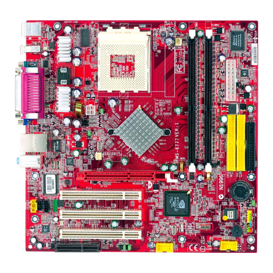
Realtek T: Line-In RTL8201BL M: Line-Out B: Mic AGP Slot BATT PCI Slot 1 VT6307 JBAT1 JSP1 nVIDIA PORT2 PCI Slot 2 nForce2 JFP2 MCP2 BIOS PCI Slot 3 Codec JFP1 USB2 JAUD1 USB1 K7N2M/K7N2GM (MS-6777/G) v1.X Micro ATX Mainboard... -
Page 12: Msi Special Features
After rebooting, click Turbo to apply the test result. Click Default to restore the default values. Features: MSI Logo links to the MSI Web site CPU Speed allows users to adjust the CPU speed through CPU Multiplier and FSB... -
Page 13: Live Bios™/Live Driver
BIOS/drivers online so that you don’t need to search for the correct BIOS/driver version throughout the Web site. To use the function, you need to install the “MSI Live Update 2” application. After installation, the “MSI Live Update 2” icon (as shown on the right) will appear on the screen. -
Page 14: Live Monitor
Live Monitor™ The Live Monitor™ is a tool used to schedule the search for the latest BIOS/drivers version on the MSI Web site. To use the function, you need to install the “MSI Live Update 2” application. After installation, the “MSI Live Monitor” icon (as shown on the right) will appear on the screen. -
Page 15: Pc Alert™ 4
MS-6777 M-ATX Mainboard PC Alert™ 4 The PC Alert 4 is a utility you can find in the CD-ROM disk. The utility is just like your PC doctor that can detect the following PC hardware status during real time operation: monitor CPU &... - Page 16 CPU and chipset. Right-click the mouse to select the skin you want to switch to. C u t e MSI Reminds You... 1. The new feature COOLER XP will work only if your mainboard supports AMD Athlon™ XP CPU.
-
Page 17: Chapter 2. Hardware Setup
Hardware Setup Chapter 2. Hardware Setup Hardware Setup This chapter tells you how to install the CPU, memory modules, and expansion cards, as well as how to setup the jump- ers on the mainboard. Also, it provides the instructions on con- necting the peripheral devices, such as the mouse, keyboard, etc. -
Page 18: Quick Components Guide
MS-6777 M-ATX Mainboard Quick Components Guide CFAN1, p.2-17 CPU, p.2-3 DDR DIMMs, p.2-7 JPW1, p.2-9 Back Panel I/O, p.2-10 JWR1, p.2-9 J3, p.2-25 FDD1, p.2-15 J T V 1 , p.2-22 J4, p.2-25 S F A N 1 , p.2-17 IDE1/2 , AGP1, p.2-26 p.2-16... -
Page 19: Central Processing Unit: Cpu
Hardware Setup Central Processing Unit: CPU ® The mainboard supports AMD Athlon™, Athlon™ XP and Duron™ processors in the 462 pin package. The mainboard uses a CPU socket called Socket A for easy CPU installation. When you are installing the CPU, make sure the CPU has a heat sink and a cooling fan attached on the top to prevent overheating. -
Page 20: Cpu Installation Procedures For Socket 462
MS-6777 M-ATX Mainboard CPU Installation Procedures for Socket 462 1. Please turn off the power and unplug the power cord before Open Lever installing the CPU. Sliding 2. Pull the lever sideways away 90 degree Plate from the socket. Make sure to raise the lever up to a 90- degree angle. -
Page 21: Installing Amd Athlon Cpu (Socket 462) Cooler Set
4. Connect the fan to the power sup- ply connector provided on your mainboard. MSI Reminds You... Please apply some heat sink paste on top of your CPU to dissi- pate the heat more effectively. -
Page 22: Cpu Clock Frequency Selection Through Jumpers
To set the clock frequency for the installed CPU, refer to Jumpers in later section. MSI Reminds You... Overheating Overheating will seriously damage the CPU and system, al- ways make sure the cooling fan can work properly to protect the CPU from overheating. -
Page 23: Memory
Hardware Setup Memory The mainboard provides: 2 DDR SDRAM DIMMs to support Dual Channel DDR266/333, max. 2GB (nForce2 IGP only) 2 DDR SDRAM DIMMs to support Single Channel DDR266/333/ 400, max. 2GB (nForce2 400 only) You can install DDR400 (nForce2 400 only)/333/266/200 modules on the DDR DIMM slots (DIMM 1~2). -
Page 24: Dimm Module Combination
3. The plastic clip at each side of the DIMM slot will automatically close. Notch Volt MSI Reminds You... You can barely see the golden finger if the module is properly inserted in the socket. -
Page 25: Power Supply
Hardware Setup Power Supply The mainboard supports ATX power supply for the power system. Be- fore inserting the power supply connector, always make sure that all compo- nents are installed properly to ensure that no damage will be caused. ATX 20-Pin Power Connector: JWR1 ATX 12V Power Connector: JPW1 The JWR1 provides power to the mainboard while the JPW1 is used to supply power to the CPU. -
Page 26: Back Panel
MS-6777 M-ATX Mainboard Back Panel The back panel provides the following connectors: Parallel (Optional) Mouse L-In L-Out Keyboard 1394 Port COM A (nForce2 IGP only) (Optional) Mouse/Keyboard Connector ® The mainboard provides a standard PS/2 mouse/keyboard mini DIN ® ® connector for attaching a PS/2 mouse/keyboard. -
Page 27: Ieee1394 Port (Optional)
Hardware Setup IEEE1394 Port (Optional) The back panel provides one standard IEEE 1394 port. The standard IEEE1394 port connects to IEEE1394 devices without external power. The IEEE1394 high-speed serial bus complements USB by providing enhanced PC connectivity for a wide range of devices, including consumer electronics audio/video (A/V) appliances, storage peripherals, other PCs, and portable devices. -
Page 28: Parallel Port Connector: Lpt1
MS-6777 M-ATX Mainboard Parallel Port Connector: LPT1 The mainboard provides a 25-pin female centronic connector as LPT. A parallel port is a standard printer port that supports Enhanced Parallel Port (EPP) and Extended Capabilities Parallel Port (ECP) mode. Pin Definition SIGNAL DESCRIPTION STROBE... -
Page 29: Rj-45 Lan Jack
CD player, Tape player, or other audio devices. Mic is a connec- tor for microphones. Line In 1/8” Stereo Audio Connectors Line Out MSI Reminds You... For more information on 6-channel audio operation, please refer to Appendix: Using 4- or 6-Channel Audio Function. 2-13... -
Page 30: Serial Port Connector
MS-6777 M-ATX Mainboard Serial Port Connector The mainboard offers one 9-pin male DIN connector as the serial port. The port is a 16550A high speed communication port that sends/receives 16 bytes FIFOs. You can attach a serial mouse or other serial devices directly to the connector. -
Page 31: Connectors
Hardware Setup Connectors The mainboard provides connectors to connect to FDD, IDE HDD, case, modem, LAN, USB Ports, IR module and CPU/System FAN. Floppy Disk Drive Connector: FDD1 The mainboard provides a standard floppy disk drive connector that supports 360K, 720K, 1.2M, 1.44M and 2.88M floppy disk types. FDD1 2-15... -
Page 32: Hard Disk Connectors: Ide1 & Ide2
IDE2 (Secondary IDE Connector) IDE2 can also connect a Master and a Slave drive. MSI Reminds You... If you install two hard disks on cable, you must configure the second drive to Slave mode by setting its jumper. Refer to the hard disk documentation supplied by hard disk vendors for jumper setting instructions. -
Page 33: Fan Power Connectors: Cfan1/Sfan1
GND. If the mainboard has a System Hardware Monitor chipset on-board, you must use a specially designed fan with speed sensor to take advantage of the CPU fan control. SENSOR +12V CFAN1 +12V Sensor SFAN1 MSI Reminds You... Always consult the vendors for proper CPU cooling fan. 2-17... -
Page 34: Front Panel Connectors: Jfp1 & Jfp2
MS-6777 M-ATX Mainboard Front Panel Connectors: JFP1 & JFP2 The mainboard provides two front panel connectors for electrical con- ® nection to the front panel switches and LEDs. JFP1 is compliant with Intel Front Panel I/O Connectivity Design Guide. JFP2 Speaker Power JFP1... -
Page 35: Front Panel Audio Connector: Jaud1
Left channel audio signal to front panel AUD_RET_L Left channel audio signal return from front panel MSI Reminds You... If you don’t want to connect to the front audio header, pins 5 & 6, 9 & 10 have to be jumpered in order to have signal output directed to the rear audio ports. -
Page 36: Front Usb Connectors: Usb1, Usb2
MS-6777 M-ATX Mainboard Front USB Connectors: USB1, USB2 The mainboard provides two USB 2.0 pin headers USB1/2 that are com- ® pliant with Intel I/O Connectivity Design Guide. USB 2.0 technology in- creases data transfer rate up to a maximum throughput of 480Mbps, which is 40 times faster than USB 1.1, and is ideal for connecting high-speed USB interface peripherals such as USB HDD, digital cameras, MP3 players, printers, modems and the like. -
Page 37: Cd-In Connector: J7
Hardware Setup CD-In Connector: J7 The connector is for CD-ROM audio connector. Aux Line-In Connector: J9 The connector is for DVD add-on card with Line-in connector. SPDIF Connector: JSP1 (Optional) The connector is used to connect SPDIF (Sony & Philips Digital Inter- connect Format) interface for digital audio transmission. -
Page 38: Tv-Out Connector: Jtv1 (Optional)
MS-6777 M-ATX Mainboard TV-Out Connector: JTV1 (Optional) The mainboard optionally provides a TV-Out connector for you to at- tach a TV-Out bracket. The TV-Out bracket offers two types of TV-Out connectors: S-Video and RCA Composite connector. Select the appropriate one to connect to the television and the television will be able to display PC’s information. -
Page 39: Ieee 1394 Connector: Port2 (Optional)
Hardware Setup IEEE 1394 Connector: PORT2 (Optional) The mainboard provides one 1394 pin header that allows you to connect IEEE 1394 ports via an external IEEE1394 bracket (optional). PORT2 Pin Definition SIGNAL SIGNAL TPA+ TPA- Ground Ground TPB+ TPB- Cable power Cable power Key (no pin) Ground... -
Page 40: Jumpers
JBAT1 Keep Data Clear Data MSI Reminds You... You can clear CMOS by shorting 2-3 pin while the system is off. Then return to 1-2 pin position. Avoid clearing the CMOS while the system is on; it will damage the mainboard. -
Page 41: Fsb Mode Jumper: J4
Safe Mode 133 MHz 100 MHz MSI Reminds You... If your computer hang while overclocking, please reset J4 to safe mode and reboot. After rebooting, enter BIOS Setup menu to reload the BIOS Setup Defaults and reset J4 to user mode. -
Page 42: Slots
MS-6777 M-ATX Mainboard Slots The motherboard provides one AGP slot, three 32-bit PCI bus slots, and one CNR slot. AGP Slot PCI Slots CNR Slot AGP (Accelerated Graphics Port) Slot The AGP slot allows you to insert the AGP graphics card. AGP is an interface specification designed for the throughput demands of 3D graphics. -
Page 43: Pci Interrupt Request Routing
Hardware Setup motherboards. Its main processing is done through software and controlled by the motherboard’s chipset. PCI Interrupt Request Routing The IRQ, acronym of interrupt request line and pronounced I-R-Q, are hardware lines over which devices can send interrupt signals to the microprocessor. -
Page 44: Chapter 3. Bios Setup
BIOS Setup Chapter 3. BIOS Setup BIOS Setup This chapter provides information on the BIOS Setup pro- gram and allows you to configure the system for optimum use. You may need to run the Setup program when: An error message appears on the screen during the system booting up, and requests you to run SETUP. -
Page 45: Entering Setup
MS-6777 M-ATX Mainboard Entering Setup Power on the computer and the system will start POST (Power On Self Test) process. When the message below appears on the screen, press <DEL> key to enter Setup. Press DEL to enter SETUP If the message disappears before you respond and you still wish to enter Setup, restart the system by turning it OFF and On or pressing the RESET button. -
Page 46: Getting Help
Press <Esc> to exit the Help screen. MSI Reminds You... The items under each BIOS category described in this chapter are under continuous update for better system performance. -
Page 47: The Main Menu
MS-6777 M-ATX Mainboard The Main Menu ® Once you enter Phoenix-Award BIOS CMOS Setup Utility, the Main Menu (Figure 1) will appear on the screen. The Main Menu allows you to select from twelve setup functions and two exit choices. Use arrow keys to select among the items and press <Enter>... - Page 48 BIOS Setup PC Health Status This entry shows your PC health status. Frequency/Voltage Control Use this menu to specify your settings for frequency/voltage control. Load Fail-Safe Defaults Use this menu to load the BIOS default values for minimal but stable system performance.
-
Page 49: Standard Cmos Features
MS-6777 M-ATX Mainboard Standard CMOS Features The items in Standard CMOS Features Menu are divided into 11 catego- ries. Each category includes no, one or more than one setup items. Use the arrow keys to highlight the item and then use the <PgUp> or <PgDn> keys to select the value you want in each item. - Page 50 BIOS Setup If your hard disk drive type is not matched or listed, you can use Manual to define your own drive type manually. If you select Manual, related information is asked to be entered to the following items. Enter the information directly from the keyboard. This information should be provided in the documentation from your hard disk vendor or the system manufacturer.
-
Page 51: Advanced Bios Features
MS-6777 M-ATX Mainboard Advanced BIOS Features Anti-Virus Protection The item is to set the Virus Warning feature for IDE Hard Disk boot sector protection. If the function is enabled and any attempt to write data into this area is made, BIOS will display a warning message on screen and beep. Settings: Disabled and Enabled. - Page 52 BIOS Setup HDD-1 The system will boot from the second HDD. HDD-2 The system will boot from the third HDD. HDD-3 The system will boot from the fourth HDD. ZIP100 The system will boot from ATAPI ZIP drive. USB-FDD The system will boot from the USB FDD. USB-ZIP The system will boot from the USB ZIP drive.
- Page 53 MS-6777 M-ATX Mainboard Typematic Rate (Chars/Sec) After Typematic Rate Setting is enabled, this item allows you to set the rate (characters/second) at which the keys are accelerated. Settings: 6, 8, 10, 12, 15, 20, 24 and 30. Typematic Delay (Msec) This item allows you to select the delay between when the key was first pressed and when the acceleration begins.
- Page 54 BIOS Setup porting Technology) capability for the hard disks. S.M.A.R.T is a utility that monitors your disk status to predict hard disk failure. This gives you an op- portunity to move data from a hard disk that is going to fail to a safe place before the hard disk becomes offline.
-
Page 55: Advanced Chipset Features
MS-6777 M-ATX Mainboard Advanced Chipset Features MSI Reminds You... Change these settings only if you are familiar with the chipset. Current CPU Clock It shows the current clock frequency of the CPU. (read only) System Performance This field allows users to control the status of system performance. Users may select [Auto] for the most stable settings by SPD. - Page 56 BIOS Setup FSB/DRAM Ratio This setting controls the ratio of CPU FSB clock & DRAM Frequency to enable the CPU & DRAM to run at different frequency combinations. Please note that the setting options vary according to the CPU FSB clock preset. Options: By SPD, 2:1, 5:3, 3:2, 4:3, 5:4, 6:5, 1:1, 5:6, 4:5, 3:4, 2:3, 3:5, 1:2.
- Page 57 MS-6777 M-ATX Mainboard FSB Spread Spectrum This item is used to enable or disable the FSB clock generator’s Spread Specturm feature. When overclocking the FSB, always set it to Disabled. Options: Disabled, 0.50%, 1.00%. AGP Spread Spectrum This item is used to enable or disable the AGP clock generator’s Spread Specturm feature.
- Page 58 BIOS Setup Frame Buffer Size (for IGP only) Frame Buffer is the video memory that stores data for video display (frame). This field is used to determine the memory size for Frame Buffer. Larger frame buffer size increases video performance. Settings: 8M, 16M, 32MB and Disabled.
-
Page 59: Integrated Peripherals
MS-6777 M-ATX Mainboard Integrated Peripherals IDE Function Setup Press <Enter> to enter the sub-menu and the following screen appears: OnChip IDE Channel 0/1 The integrated peripheral controller contains an IDE interface with support for two IDE channels. Choose [Enabled] to activate each channel separately. - Page 60 BIOS Setup each device. The settings are: Auto, Mode 0, Mode 1, Mode 2, Mode 3, Mode 4. Primary/Secondary Master/Slave UDMA Ultra DMA/33 implementation is possible only if your IDE hard drive supports it and the operating environment includes a DMA driver (Windows 95 OSR2 or a third-party IDE bus master driver).
- Page 61 MS-6777 M-ATX Mainboard an audio device is detected, the onboard AC’97 (Audio Codec’97) con- troller will be enabled; if not, it is disabled. Disable the controller if you want to use other controller cards to connect an audio device. Settings: Auto, Disabled.
- Page 62 BIOS Setup Onboard FDC Controller Select Enabled if your system has a floppy disk controller (FDD) in- stalled on the system board and you wish to use it. If you install add-on FDC or the system has no floppy drive, select Disabled in this field. The settings are: Enabled and Disabled.
- Page 63 MS-6777 M-ATX Mainboard EPP Mode Select The onboard parallel port is EPP Spec. compliant, so after the user chooses the onboard parallel port with the EPP function, the following message will be displayed on the screen: “EPP Mode Select.” At this time either EPP 1.7 spec or EPP 1.9 spec can be chosen.
-
Page 64: Power Management Setup
BIOS Setup Power Management Setup MSI Reminds You... S3-related functions described in this section are available only when your BIOS supports S3 sleep mode. Sleep State This item specifies the power saving modes for ACPI function. If your oper- ating system supports ACPI, such as Windows 98SE, Windows ME and Win- dows 2000, you can choose to enter the Standby mode in S1(POS) or S3 (STR) fashion through the setting of this field. - Page 65 MS-6777 M-ATX Mainboard to these modes: Suspend Mode and HDD Power Down. There are three op- tions for power management: Min Saving Minimum Power Management. Suspend Mode=1 Hour Max Saving Maximum Power Management. Suspend Mode=1 Min User Define Allows end users to configure each mode separately. Video Off Method This determines the manner in which the monitor is blanked.
- Page 66 Time (hh:mm:ss) Alarm You can choose what hour, minute and second the system will boot up. MSI Reminds You... If you have changed this setting, you must let the system boot up until it enters the operating system, before this function will work.
- Page 67 MS-6777 M-ATX Mainboard MSI Reminds You... IRQ (Interrupt Request) lines are system resources allocated to I/ O devices. When an I/O device needs to gain attention of the oper- ating system, it signals this by causing an IRQ to occur. After re-...
-
Page 68: Pnp/Pci Configurations
BIOS Setup PNP/PCI Configurations This section describes configuring the PCI bus system and PnP (Plug & Play) feature. PCI, or Peripheral Component Interconnect, is a system which allows I/O devices to operate at speeds nearing the speed the CPU itself uses when communicating with its special components. - Page 69 MS-6777 M-ATX Mainboard ® such as Windows 95/98. If you set this field to “manual” choose specific resources by going into each of the sub menu that follows this field (a sub menu is preceded by a “ ”). The settings are: Auto (ESCD), Manual. IRQ Resources The items are adjustable only when Resources Controlled By is set to Manual.
-
Page 70: Pc Health Status
BIOS Setup PC Health Status This section shows the status of your CPU, fan, overall system status, etc. Monitor function is available only if there is hardware monitoring mecha- nism onboard. CPU Warning Temperature This item is used to specify a thermal limit for CPU. If CPU temperature reaches the specified limit, the system will issue a warning which allows you to prevent the CPU overheat problem. -
Page 71: Frequency/Voltage Control
MS-6777 M-ATX Mainboard Frequency/Voltage Control Use this menu to specify your settings for frequency/voltage control. AGP Clock Control This item allows users to set the AGP clock manually or by default. Options: Default, Manual. AGP Clock Value When AGP Clock Control is set to Manual, users can key in a DEC number between 66 and 120. -
Page 72: Load Fail-Safe/Optimized Defaults
BIOS Setup Load Fail-Safe/Optimized Defaults The two options on the main menu allow users to restore all of the BIOS settings to the default Fail-Safe or Optimized values. The Optimized Defaults are the default values set by the mainboard manufacturer specifically for op- timal performance of the mainboard. -
Page 73: Set Supervisor/User Password
FEATURES menu. If the Security Option is set to System, the password is required both at boot and at entry to Setup. If set to Setup, password prompt only occurs when you try to enter Setup. MSI Reminds You... About Supervisor Password & User Password: Supervisor password: Can enter and change the settings of the setup menu. -
Page 74: Appendix A: Using 4- Or 6-Channel Audio Function
Using 4- or 6-Channel Audio Function Appendix A: Using 4- or 6-Channel Au- dio Function You need to install the NVIDIA nForce System Drivers to function prop- erly before you can get access to 4-/6-channel audio operations. Follow the procedures described below to install the drivers for different operating systems. TOPICS Installing the Audio Driver Using 4- or 6-Channel Audio Function... -
Page 75: Installing The Audio Driver
MS-6777 M-ATX Mainboard Installing the Audio Driver Installation for Windows 98SE/ME/2000/XP ® ® For Windows 2000, you must install Windows 2000 Service Pack2 or later before installing the driver. ® The following illustrations are based on Windows XP environment and could look slightly different if you install the drivers in different operating systems. - Page 76 Using 4- or 6-Channel Audio Function Click here 4. Click Finish to restart the system. Select this option Click here...
-
Page 77: Using 4- Or 6-Channel Audio Function
MS-6777 M-ATX Mainboard Using 4- or 6-Channel Audio Function After installing the audio driver, you are able to use the 4-/6-channel audio feature now. To enable 4- or 6-channel audio operation, first connect 4 or 6 speakers to the appropriate audio connectors, and then select 4- or 6- channel audio setting in the software utility. - Page 78 Using 4- or 6-Channel Audio Function 2. On the Options menu, click Advanced Controls. 3. Click Advanced. Check here...
- Page 79 MS-6777 M-ATX Mainboard 4. Check Rear Speakers connected to Line In and Center speaker and subwoofer connected to Microphone for 6-channel audio output. Check here 5. Click Close to exit.
- Page 80 Using 4- or 6-Channel Audio Function Connecting the Speakers When you have set the Multi-Channel Audio Function mode properly in the software utility, connect your speakers to the correct phonejacks in accordance with the setting in software utility. 2-Channel Mode for Stereo-Speaker Output Refer to the following diagram and caption for the function of each phonejack on the back panel when 2-Channel Mode is selected.
- Page 81 MS-6777 M-ATX Mainboard Back Panel Line Out (Rear channels) Line Out (Front channels) * Line In function is converted to Line Out function when 4-Channel Mode for 4-Speaker Output is selected. 6-Channel Mode for 6-Speaker Output Refer to the following diagram and caption for the founction of each jack on the back panel when 6-Channel Mode is selected.
-
Page 82: Appendix B: Using The Tv-Out Function
Using the TV-Out Function Appendix B: Using the TV-Out Function You need to install the TV-Out bracket before you can get access to the TV-out function. Follow the procedures described later to set up the TV- Out bracket and configure the display settings. Note that the TV-Out bracket works with the onboard graphic core. -
Page 83: Installing The Tv-Out Bracket
MS-6777 M-ATX Mainboard Installing the TV-Out Bracket 1. Take out the TV-Out bracket. Foolproof design (RCA Composite) (S-Video) 2. Locate the TV-out connector (JTV1) on the mainboard. 3. Connect the TV-Out bracket to the connector. Align the foolproof design with the pin layout of the connector to avoid mis-inserting. -
Page 84: Connecting S-Video And Rca Cables
Using the TV-Out Function Connecting S-Video and RCA Cables Connecting S-Video cable 1. Connect one end of the S-Video cable to the TV-Out(S) connector. S-Video cable 2. Connect the other end of the S-Video cable to the TV. - Page 85 MS-6777 M-ATX Mainboard Connecting RCA cable 1. Connect one end of the RCA cable to the TV-Out(C) connector. The RCA cable usually comes with three connecotrs on both ends. The white or red connector is for audio while the yellow one is for video. RCA cable White (Audio) Red (Audio)
-
Page 86: Display Setup
Using the TV-Out Function Display Setup The following procedures describe display setup using Windows XP. Windows 2000/ME/9X screens are slightly different but the procedures are the same as described. To enable the TV-Out function, follow this procedure: 1. Restart the computer. After entering the Windows OS, left-click in the window and the screen will pop up a menu. - Page 87 MS-6777 M-ATX Mainboard 4. In the nView tab, click Device Settings to set up or change settings related to the output device used for the current display. click here 5. In the Device Selection tab, first click TV and then Change Format.
- Page 88 Using the TV-Out Function 6. Select your local TV format. 7. (refer to Step 4) Under Device Settings, click Device Adjust- ments. In the Screen Adjustment tab, use the 4-way navigation keys to adjust the screen position. Click Default to restore the factory setup value.
-
Page 89: Troubleshooting
Q: How do I know what MSI D-LED or D-bracket light mean? A: Please follow the special tech issue, http://www.msi.com.tw/support/ techexpress/special_tech/smartled.htm Q: I used my MSI motherboard and got an error message, "Primary IDE Channel No 80 Conductor Cable Installed" while the system detected hard drives. - Page 90 2. Try to clear the CMOS If problem still persists, ask your reseller for new BIOS chip or contact one of MSI office near your place for new BIOS chip http:// www.msi.com.tw/contact/main.htm Q: Should I update my BIOS, once a new BIOS is released? A: A new BIOS is usually released due to the following reasons: 1.
- Page 91 BIOS, unless you really have to. Q: How do I update the BIOS? A: Please refer to http://www.msi.com.tw/support/bios/note.htm for details. Q: How do I identify the BIOS version? A: Upon boot-up, the 1st line appearing after the memory count is the BIOS version.
- Page 92 MS-6737E ATX Mainboard MS-6777 M-ATX Mainboard Q: After I flashed the BIOS and rebooted the system, the screen went blank. A: For AMI BIOS Rename the desired AMI BIOS file to AMIBOOT.ROM and save it on a floppy disk. e.g. Rename A569MS23.ROM to AMIBOOT.ROM Insert this floppy disk in the floppy drive.
-
Page 93: Glossary
Glossary Glossary Glossary ACPI (Advanced Configuration & Power Interface) This power management specification enables the OS (operating system) to control the amount of power given to each device attached to the computer. Windows 98/98SE, Windows 2000 and Windows ME can fully support ACPI to allow users managing the system power flexibly. - Page 94 MS-6777 M-ATX Mainboard contents of frequently accessed RAM locations and the addresses where these data items are stored. Chipset A collection of integrated chips designed to perform one or more related functions. For example, a modem chipset contains all the primary circuits for transmitting and receiv- ing data;...
- Page 95 Glossary ECC Memory (Error Correcting Code Memory) A type of memory that contains special circuitry for testing the accuracy of data and correcting the errors on the fly. EEPROM Acronym for Electrically Erasable Programmable Read-Only Memory. An EEPROM is a special type of PROM that can be erased by exposing it to an electrical charge. Like other types of PROM, EEPROM retains its contents even when the power is turned off.
- Page 96 MS-6777 M-ATX Mainboard IDE (Integrated Drive Electronics) A type of disk-drive interface widely used to connect hard disks, CD-ROMs and tape drives to a PC, in which the controller electronics is integrated into the drive itself, eliminating the need for a separate adapter card. The IDE interface is known as the ATA (AT Attachment) specification.
- Page 97 Glossary LBA (Logical Block Addressing) Logical block addressing is a technique that allows a computer to address a hard disk larger than 528 megabytes. A logical block address is a 28-bit value that maps to a specific cylinder-head-sector address on the disk. 28 bits allows sufficient variation to specify addresses on a hard disk up to 8.4 gigabytes in data storage capacity.
- Page 98 MS-6777 M-ATX Mainboard PS/2 Port A type of port developed by IBM for connecting a mouse or keyboard to a PC. The PS/2 port supports a mini DIN plug containing just 6 pins. Most modern PCs equipped with PS/2 ports so that the special port can be used by another device, such as a modem.
Need help?
Do you have a question about the K7N2M and is the answer not in the manual?
Questions and answers