Table of Contents
Advertisement
Quick Links
Download this manual
See also:
Owner's Manual
Advertisement
Table of Contents

Subscribe to Our Youtube Channel
Related Manuals for Fluid E820


Summary of Contents for Fluid E820
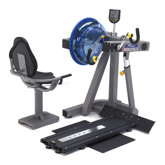
- Page 1 Owners Manual...
- Page 2 Training with the E820 As with any piece of fitness equipment, consult a physician be- fore beginning your E820 exercise program. CAUTION Use two hands and follow all safety instructions whenever raising or lowering the E820 control arm. Warning Do not remove hands while crank is in motion. The crank will...
-
Page 3: Table Of Contents
Contents Box Contents Assembly Instructions Install the Baseplate Install Baseplate to Mainframe Seat Assemby Attaching Armrest Lower frame Attaching Armrest cable to Cable Pivot Install Seat Back and Seat Install Seat onto Baseplate Control Arm Tank Filling and Water Treatment Long Term Water Treatment and Basic Operation Rower Ergometer Using the First Degree Fitness USB Interface... -
Page 4: Box Contents
Box Contents... - Page 5 Item Qty Description Item Qty Description Main Frame with Telescoping 4 M8 Washer Tube and Internal Gas Assist Shock 1 Baseplate (Install P-8) 3 M10 Washer 1 Seat (Install P-11) 4 M8 Springs Washer 8 M6x20mm bolt 1 4mm Allen Key 4 M8x15mm blot 1 6mm Allen Key 1 M8x25mm blot...
-
Page 6: Assembly Instructions
Assembly Instructions 4x 8x15mm bolts and 4x M8 spring washers Adjuster knob Remove contents from box. Attach telescoping tube to the underside of the control arm using 4x M8x15mm bolts[5] and 4x M8 spring washers[15]. The control arm is heavy and may swing freely during this CAUTION stage of assembly. - Page 7 Note: Allow 15 minutes for the thread locker to activate before first time use. Check pedal tightness periodically thereaf- ter with a 15mm wrench. Secure right pedal onto Crank arm. The pedal threads have a blue coating which will feel very tight when threaded onto the crank arm. This is a type of thread lock- er, and once in contact with the crank arm threads will activate in approximately 15minutes.
-
Page 8: Install The Baseplate
Install the Baseplate T-Track Bolt pack Channel Channel Right Left Footplate Footplate Contents: 1x T-Track 2x Footplate 1x Channel Right 1x Bolt Pack (for both baseplate/seat) 1x Channel Left... - Page 9 Footplate T-Track Tilt the T-Channel slightly to allow the footplate (with pre-installed bolts) to slide underneath as shown. Left Channel Channel Slot 4x 8x45mm Slide Channel bolts forward Mount the Left Channel over the top of the footplate dome bolts and then slide for- ward.
-
Page 10: Install Baseplate To Mainframe
Foot leveler Stand Baseplate upright to install 4x Foot levelers as shown. Once foot levelers are installed, the completed baseplate can be installed onto the mainframe of the E820. Mounting pins on E820 Mainframe Mount the baseplate onto the Mainframe using mounting pins as a locator... -
Page 11: Seat Assemby
Seat Assembly Seat Main Frame Armrest Assembly Bolt Pack Seat back Seat CONTENTS: 1x Seat Main Frame 1x Lower Seat 1x Armrest Assembly 1x Upper Seat back 1x Bolt Pack (Note Bolts/Washers/Nuts are for both Seat and Footplate) You will need the Lower Frame, Armrest Assembly and the following bolts/ washers/nuts from the bolt Pack: 1x M8x70mm Bolt 3x M8 Nylock Nut... -
Page 12: Attaching Armrest Lower Frame
Attaching Armrest to Lower frame Mount the Armrest onto the Lower frame from behind as shown. Important! Before securing bolts (see following page), thread the plastic tie at- tached to the armrest cable through the hole as shown right. Plastic tie Secure Armrest with M8x70mm Bolt[8], M8 Nylock Nut[10] and M8 Washer[13] as shown... - Page 13 M8x25mm Bolt[6] and M8 Washer[13] 2x M8x45mm Bolt[7],2x M8 Nylock Nut [10] and 2x M8 Washer[13]...
-
Page 14: Attaching Armrest Cable To Cable Pivot
Attaching Armrest cable to Cable Pivot Locate plastic tie, then depress Cable Pivot forward to allow plastic tie to be pulled through the hole in front. Once the cable end is through the hole, slide it forward as shown upper right to prevent cable end from slipping back through. -
Page 15: Install Seat Back And Seat
Install Seat Back and Seat Seat Frame, Seat Back and Seat, 8x M6x20mm Bolt[4] and 8x M6 Washer [12] Install Seat Using 4x M6x20mm Bolt[4]/ Washer[12]. Install Seat Back with as shown with 4x M6x20mm Bolt[4]/Washer[12] Seat Once seat pads are installed the assem- bly will be complete. -
Page 16: Install Seat Onto Baseplate
Install Seat onto Baseplate Seat Stop: Must be lowered to allow seat onto Baseplate track. Must ALWAYS be in the LOCKED position when seat is occupied on Baseplate. Must be lowered to allow seat removal. To LOCK, raise and locate. To Seat Installation: Tilt the seat slightly upward to allow the front rollers to en- gage the channel. -
Page 17: Control Arm
Control Arm Chain tensioning bolts: Allows for tightening the chain or adjustment from side to side. Make sure when tightening only to adjust the same amount for both bolts, otherwise the sprocket will be misaligned. Note: Tightening the right bolt only will pull the right side of the crank assembly to- ward you, tightening the left will pull the left side toward you. -
Page 18: Tank Filling And Water Treatment
Tank Filling and Water Treatment Note: A large bucket is required for filling (Not included). In areas where tap water quality is known to be poor, FDF recommends the use of distilled water. Open the tank plug and insert hose into tank (rotating the impeller slightly may be necessary to allow the hose to pass), move the tank adjuster handle to level 20 and begin filling. -
Page 19: Long Term Water Treatment And Basic Operation
Long term water treatment: Water treatment schedules for the E820 will vary according to the fluid tanks exposure to sunlight but expect 8-12 months near a bright, sunlit window and 2-4 years for a darker location. At the point of finding the water slightly green, add a Chlorine tablet. -
Page 20: Rower Ergometer
You can choose to change UNITS displayed UNITS: Displays WATTS, SPM, HR, 500/m LEVEL: Adjustable from 1-20. Match LEVEL number with resistance level on the Fluid tank. SET: Changes Time, Distance parameters PROGRAM: Clears current exercise program RESET: Clears data... -
Page 21: Using The First Degree Fitness Usb Interface
Using the First Degree Fitness USB Interface Description: The USB connectivity now built in to all new models of FDF Console and IPM allow you to enhance your exercise experience by connecting to your home PC or Laptop. Using FDF's own sample applications you can exercise while enjoying your favorite movies. -
Page 22: Maintenance Chart
Tighten as required using chain tensioning bolts lo- cated at the end of the control arm. E820 pedals. Tighten weekly using The pedals should be 15mm box wrench checked on a regular ba- (supplied) sis. A loose pedal can... -
Page 23: Troubleshooting
Contact your local service when rowing. erratic computer center if this fails to address the problem. display). The E820 comput- Batteries installed Reinstall batteries in correct position and er does not illumi- incorrectly or need try again. If the LCD screen fails to illumi- nate after battery replacing. -
Page 24: Tank Belt Adjustment
Tank Belt Adjustment Remove large metal inspection plate as shown above right. Using a long tool, push out the rear end cap as pictured right. This will give you access to the tank tensioning bolt (shown bottom right). End Cap Loosen both the front and rear tank bolts as shown below. -
Page 25: Warranty
This product is designed and constructed for use in any Health Club / Fitness Studio application First Degree Fitness Limited warrants that the Fluid Upper Body Ergometer (model UB-E820), purchased from an authorised agent and in its undamaged original packaging, is free from defects in materials and workmanship. First Degree Fitness Limited or its agent will, at their discretion, repair or replace parts that become defective within the warranty period, subject to the specific inclusions and exclusions below.
Need help?
Do you have a question about the E820 and is the answer not in the manual?
Questions and answers