White Rodgers 1F78 Installation Instructions Manual
Hide thumbs
Also See for 1F78:
- Installation instructions manual (17 pages) ,
- User manual (6 pages) ,
- Installation instructions manual (13 pages)
Advertisement
Table of Contents
Installation Instructions for
Heating & Air Conditioning
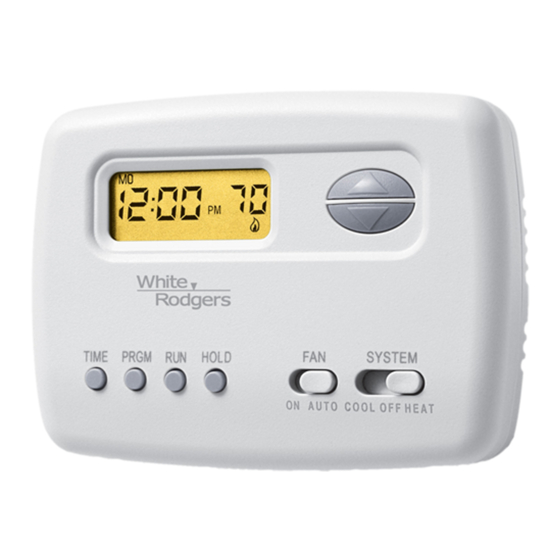
1F78
5/2 Day Programmable Thermostat
YOUR THERMOSTAT REPLACES
Typical System Compatibility Chart
Standard Heat Only Two Wire Gas or Oil Fired Systems (24 volt)
Electronic Ignition Heat Only Two Wire Systems (24 volt)
Electronic Ignition Heat Only Gas or Oil Fired Systems (24 volt)
Standard Heat/Cool Systems (24 volt)
Heat/Cool Systems Electric Heat (24 volt)
Heat Only Electric Heat Systems (24 volt)
Cool Only Systems (24 volt)
Heat Pump Systems (No Aux. or Emergency Heat)
Hot Water Zone Heat Only (Two Wire) Systems
Hot Water Zone Heat Only (Three Wire) Systems
Line Voltage Heating or Baseboard 110/240 Volt Systems
Millivolt Systems Floor or Wall Furnaces
12 VDC Mobile Home Application
Multistage Systems
Systems Exceeding 30VAC, 1.5 Amp
2
THERMOSTAT DETAILS
-
W903 Clip to
Disable EMR
Feature
W903
W904 Clip for
W904
Celsius Display
Mounting
hole
W905
W905 Clip for
Hydronic System
NOTE: Earlier models refer to 37-7006 for jumper locations.
Figure 1. Thermostat base
1E78
Yes
Yes
Yes
Yes
Yes
Yes
Yes
Yes
Yes
No
No
Yes
Yes
No
No
Mounting
hole
-
+
+
W
B
RC
RH
G
O
Y
ELEC
GAS
Electric/Gas
Switch
www.white-rodgers.com
www.emersonclimate.com
CONTENTS
Preparations .................................................. 1
Thermostat Details ........................................ 1
Removing Old Thermostat ............................. 1
Mounting and Wiring ...................................... 2
Check Thermostat Operation ......................... 3
Programming your Thermostat ...................... 4
Specifications ................................................ 6
Troubleshooting ............................................. 6
1
PREPARATIONS
Assemble tools required below.
HAND OR POWER
DRILL WITH 3/16 INCH
DRILL BIT, IF NEEDED
Failure to follow and read all instructions carefully
before installing or operating this control could cause
personal injury and/or property damage
3
REMOVING OLD THERMOSTAT
CAUTION
!
To prevent electrical shock and/or equipment damage,
disconnect electrical power to the system at the main fuse
or circuit breaker until installation is complete.
Before removing wires from old thermostat's switching subbase,
label each wire with the terminal designation it was removed
from.
1. Remove Old Thermostat: A standard heat/cool thermostat
consists of three basic parts:
a. The cover, which may be either a snap-on or hinge type.
b. The base, which is removed by loosening all captive screws.
c. The switching subbase, which is removed by unscrewing
the mounting screws that hold it on the wall or adaptor plate.
2. Shut off electricity at the main fuse box until installation is
complete. Ensure that electrical power is disconnected.
3. Remove the front cover of the old thermostat. With wires still
attached, remove wall plate from the wall. If the old thermostat
has a wall mounting plate, remove the thermostat and the wall
mounting plate as an assembly.
4. Identify each wire attached to the old thermostat.
5. Disconnect the wires from the old thermostat one at a time. DO
NOT LET WIRES FALL BACK INTO THE WALL.
6. Install new thermostat using the following procedures.
FLAT BLADE SCREWDRIVER
WIRE CUTTER/STRIPPER
PART NO. 37-6614C
Replaces 37-6614B
1027
Advertisement
Table of Contents
Troubleshooting

Related Manuals for White Rodgers 1F78


Summary of Contents for White Rodgers 1F78
-
Page 1: Table Of Contents
Installation Instructions for Removing Old Thermostat ......1 Mounting and Wiring ........2 Heating & Air Conditioning Check Thermostat Operation ......3 Programming your Thermostat ...... 4 1F78 Specifications ..........6 Troubleshooting ..........6 5/2 Day Programmable Thermostat YOUR THERMOSTAT REPLACES PREPARATIONS... -
Page 2: Removing Old Thermostat
REMOVING OLD THERMOSTAT CAUTION CONTINUED FROM FIRST PAGE Take care when securing and routing wires so they do not short to adjacent terminals or rear of thermostat. Personal injury and/or property damage may occur. ATTENTION! This product does not contain mercury. However, this product may replace a unit which contains mercury. -
Page 3: Check Thermostat Operation
MOUNTING AND WIRING CONTINUED FROM SECOND PAGE JUMPER THERMOSTAT WIRE THERMOSTAT SYSTEM SYSTEM Cooling Heating 24 VAC 120 VAC System Relay System Heating Neutral Relay System HEATING TRANSFORMER 24 VAC NOTE 120 VAC Neutral For 2-wire Heat only, attach to RH and W TRANSFORMER 24 VAC 120 VAC... -
Page 4: Buttons And Switches
CHECK THERMOSTAT OPERATION CONTINUED FROM THIRD PAGE Before you begin using your thermostat, you should be familiar with its features and with the display and the location and operation of the thermostat buttons. Your thermostat consists of two parts: the thermostat cover and the base. To remove the cover, gently pull it straight out from the base. -
Page 5: Programming Your Thermostat
Entering Your Program play to match your old thermostat. This can be accomplished (within a ±3° range) as follows: Follow these steps to enter the heating and cooling programs you 1. Press PRGM and RUN buttons at the same time. have selected. -
Page 6: Specifications
PROGRAMMING YOUR THERMOSTAT CONTINUED FROM FIFTH PAGE Check Your Programming 6. Repeat steps 4 and 5 to select the start time and heating tem- perature for the 2nd heating program period. Follow these steps to check your thermostat programming one final 7. -
Page 7: Troubleshooting
TROUBLESHOOTING CONTINUED FROM SIXTH PAGE Symptom Possible Cause Corrective Action No Heat (continued) Diagnostic: Set SYSTEM Switch to HEAT and the Heating system requires service or raise thermostat requires replacement. setpoint above room temperature. Within a few seconds the thermostat should make a soft click sound. - Page 8 Homeowner Help Line: 1-800-284-2925 White-Rodgers is a division of Emerson Electric Co. The Emerson logo is a www.white-rodgers.com trademark and service mark www.emersonclimate.com of Emerson Electric Co.
Need help?
Do you have a question about the 1F78 and is the answer not in the manual?
Questions and answers