Table of Contents
Advertisement
Quick Links
Advertisement
Table of Contents

Related Manuals for ClearView Phoenix 32HP


Summary of Contents for ClearView Phoenix 32HP
- Page 1 Network Video Recorder Quick Start Guide Version 1.5.0...
-
Page 2: Table Of Contents
Table of Contents Hardware Installation and Connection ................1 1.1 Check Unpacked NVR ..................1 1.2 About Front Panel and Rear Panel ..............1 1.3 After Remove the Chassis ..................1 1.4 HDD Installation ..................... 1 1.5 Front Panel ......................3 1.6 Rear Panel ...................... - Page 3 Welcome Thank you for purchasing our network video recorder! This quick start guide is designed to be a reference tool for your system. Please open the accessory bag to check the items one by one in accordance with the list below. Contact your local retailer ASAP if something is missing or damaged in the bag.
- Page 4 Important Safeguards and Warnings 1.Electrical safety All installation and operation here should conform to your local electrical safety codes. The product must be grounded to reduce the risk of electric shock. We assume no liability or responsibility for all the fires or electrical shock caused by improper handling or installation.
- Page 5 Be installed in well ventilated place; do not block the vent. Accessories Check the accessories after opening the box: Please refer to the packing list in the box *...
-
Page 6: Hardware Installation And Connection
1 Hardware Installation and Connection Note: All the installation and operations here should conform to your local electric safety rules. 1.1 Check Unpacked NVR When you receive the NVR from the forwarding agent, please check whether there is any visible damage. The protective materials used for the package of the NVR can protect most accidental clashes during transportation. - Page 7 ○ ○ ○ Turn the device upside down and Fix the HDD firmly. Connect the HDD cable and then turn the screws in firmly. power cable. ○ ○ Put the cover in accordance with Secure the screws in the rear panel and the side panel. the clip and then place the upper cover back.
-
Page 8: Front Panel
and the HDD port respectively. Loosen the power to the device and then fix screws of the rear cable of the chassis and connect another end of panel. the power cable to the HDD port. 1.5 Front Panel 1.5.1 WiFI-NVR-4 Series The front panel is shown as in Figure 1-1. -
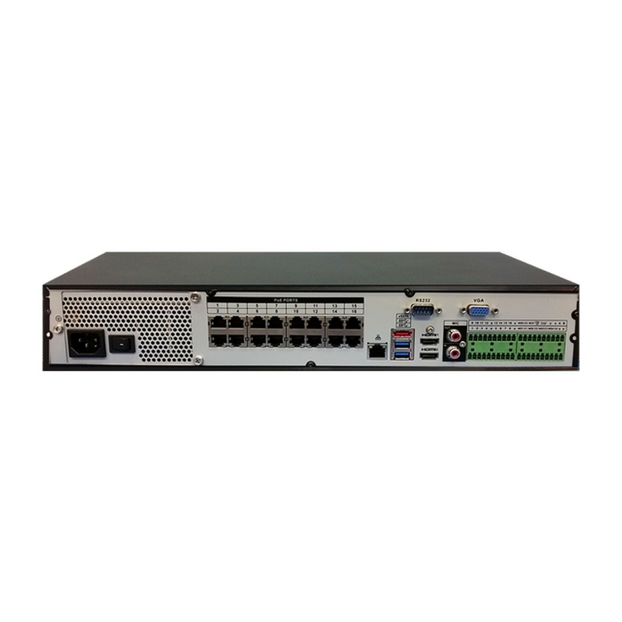
Page 9: Rear Panel
Icon Name Function Network status indicator The blue light is on when the network connection is light abnormal. POWER Power status indicator light The blue light is on when the power connection is USB2.0 port Connect to peripheral USB 2.0 storage device, mouse, burner and etc. - Page 10 Port Name Connection Function Power socket. For NVR41 series, input DC 12V/2A. Power input port For NVR41-P series, input DC 48V/1.5A. For NVR41-8P series, input DC 48V/2A. MIC IN Audio input port Bidirectional talk input port. It is to receive the analog audio signal output from the devices such as microphone, pickup.
- Page 11 Name Function Alarm input port 1~16 There are four groups. The first group is from 1~16 port 1 to port 4, the second group is from port 5 to port 8, the third group is from 9 to 12, and the fourth group is from 13 to 16.
- Page 12 Name Function Built-in Switch. Support PoE. PoE PORTS 8 PoE ports The 8 PoE ports series products supports total 48V 120W power. One PoE port max supports 15W. Built-in Switch. Support PoE. The 16 PoE ports PoE PORTS 16 PoE ports series products supports total 150W power.
-
Page 13: Gui Operation
2 GUI Operation 2.1 Boot up Caution Before the boot up, please make sure: For device security, please connect the NVR to the power adapter first and then connect the device to the power socket. The rated input voltage matches the device power on-off button. Please make sure the power wire connection is OK. -
Page 14: Smart Add
Username: 666666. Password: 666666. Username: default. Password: default. You can use USB mouse to input. Click to switch between numeral, English character (small/capitalized) and denotation. Figure 2-2 Important: For security reason, please modify password after you first login. Within 30 minutes, three times login failure will result in system alarm and five times login failure will result in account lock! 2.3 Smart Add... -
Page 15: Remote Device
Figure 2-4 Please refer to the user’s manual for detailed information. 2.4 Remote Device From Main menu->Setting->Camera->Remote device or right click mouse on the preview interface and then select remote device item, you can see the following interface. See Figure 2-5. Figure 2-5 Tips In the preview interface, for the channel of no IPC connection, you can click the icon “+”... - Page 16 See Figure 2-7. Important Please note the manual add function is for ClearView, Panasonic, Sony, Dynacolor, Samsung, AXIS, Arecont, ONVIF and custom. When the type is the custom, you can just input URL address, user name and password connect to the network camera without considering network camera manufacture. Please...
-
Page 17: Schedule
Figure 2-7 2.5 Schedule Note: You need to have proper rights to implement the following operations. Please make sure the HDDs have been properly installed. After the system booted up, it is in default 24-hour regular mode. You can set record type and time in schedule interface. - Page 18 Holiday: It is to set holiday setup. Please note you need to go to the General interface (Main Menu- >Setting->System->General) to add holiday first. Otherwise you can not see this item. Pre-record: System can pre-record the video before the event occurs into the file. The value ranges from 1 to 30 seconds depending on the bit stream.
-
Page 19: Realtime Playback
Please check the box to select the corresponding function. After completing all the setups please click save button, system goes back to the previous menu. There are color bars for your reference. Green color stands for regular recording, yellow color stands for motion detection and red color stands for alarm recording. - Page 20 Move you mouse to the top centre of the video of current channel, you can see system pops up the preview control interface. See Figure 2-13. If your mouse stays in this area for more than 6 seconds and has no operation, the control bar automatically hides. Figure 2-13 Name Name...
-
Page 21: Web Operation
3 Web Operation Important Slightly difference may be found in the interface due to different series. The following operation is based on 32-channel series product. This series NVR product support the Web access and management via PC. Web includes several modules: Monitor channel preview, record search, alarm setup, system configuration, PTZ control, monitor window and etc. -
Page 22: Login
address, otherwise it can refresh to the newly added device and memorize the <PoE port>--- <Channel>. If it is your second time to insert the PoE, system can check the saved MAC address according to <Channel>---<IPC mac> map to make sure current IPC has connected or not. If system finds the previous information and the channel is idle, system can map it to the previously used channel. - Page 23 For the LAN mode, after you logged in, you can see the main window. See Figure 3-2. Click the channel name on the left side; you can view the real-time video. Figure 3-2 3.3.2 WAN Login In WAN mode, after you logged in, the interface is shown as below. See Figure 3-3. Figure 3-3 For detailed operation information, please refer to the User’s Manual included in the resources CD.
- Page 24 For detailed operation introduction, please refer to our resource CD included in your package for electronic version of the User’s Manual. Slight difference may be found in user interface. All the designs and software here are subject to change without prior written notice. ...
Need help?
Do you have a question about the Phoenix 32HP and is the answer not in the manual?
Questions and answers