Table of Contents
Advertisement
Advertisement
Table of Contents

Summary of Contents for Sea & Sea YS-D1
- Page 1 03114 03115 UNDERWATER STROBE YS-D1 取扱説明書 Instruction Manual...
- Page 2 Introduction Thank you for purchasing SEA&SEA products. Please read this instruction manual carefully prior to using your underwater strobe. Only with a thorough understanding of this manual's content will you be able to use the strobe correctly. After reading the manual, please be sure to keep it in a place where you can easily come back to it at any time.
-
Page 3: Table Of Contents
Contents Safety Precautions ................. E-3 Safety Precautions for Use of Battery ............ E-6 Precautions on Handling the O-ring ............E-8 Accessories ..................E-10 Identification of Parts ..............E-11 Operation ..................E-12 Ready/TTL lamp ................E-13 YS Mount Strobe Adaptor/Ball Mount Strobe Adaptor....E-14 Preparation for Setting Up .............. -
Page 4: Safety Precautions
Safety Precautions For safe handling of the product, please read the following precautions carefully before use. Failure to heed the precautions listed below could result in serious consequences. To prevent injury or damage to yourself and/or others, please observe the precautions as they contain highly important information related to personal and product safety. - Page 5 Safety Precautions Do not fire the strobe or illuminate the light towards a driver of a vehicle to avoid causing accidents. Do not operate the product while driving a vehicle. Inattention could result in accidents. For use on land, do not operate the product at precarious foothold. It may cause falling, injury or product damage.
- Page 6 Safety Precautions Be careful when touching the product immediately after firing repeatedly or lighting for a long time. The product may get hot enough to burn you. Avoid strong shocks / impacts or excess stress to prevent malfunction, damage or breakdown. Make sure that the product has been securely mounted to other products in order to prevent injury, fall or missing.
-
Page 7: Safety Precautions For Use Of Battery
Safety Precautions for Use of Battery DANGER Never expose the battery to flame or fire, or to excessive heat. Never attempt to disassemble, alter or directly solder the battery. There are no user-serviceable parts. Tampering with battery may expose you to dangerous voltage, battery acid, or electrical shock. - Page 8 Safety Precautions for Use of Battery CAUTION Avoid strong shocks / impacts or excess stress to batteries. For handling and recharging of a battery, refer to the instruction manual of the battery/dedicated charger. Do not use or discharge the battery at ambient temperatures below 0℃ (32°F) or above 50℃...
-
Page 9: Precautions On Handling The O-Ring
Precautions on Handling the O-ring This product is kept watertight by the O-ring. To keep the O-ring functioning properly, please observe the following. Improper handling of the O-ring could cause flooding. CAUTION SEA&SEA products use blue O-rings. These O-rings are impregnated with silicone oil through a special process. - Page 10 Precautions on Handling the O-ring Coat with silicone grease Silicone grease protects the O-ring from chafing. After checking the O-ring to make sure that there are no scratches, dust, or debris, apply a light coating of silicone grease to the entire O-ring with your finger. Applying too much grease will make it easier for dust and debris to adhere to the O-ring, and could cause flooding.
-
Page 11: Accessories
Before using this model, check to make sure that all accessories are present. YS Mount Strobe Adaptor YS-D1 Diffuser-100 (mounted on the YS-D1) Silicone Grease Diffuser-120 Ball Mount Strobe Adaptor Fixing Bolt Spare cap bolt (×1) M4 Hexagon Wrench Diffuser Strap (×2) O-ring Maintenance Manual YS-D1 Instruction Manual (this manual) E-10... -
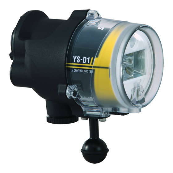
Page 12: Identification Of Parts
Identification of Parts Target light (P.E-13) Fiber-optic cable socket (for additional strobe (P.E-22)) Strap eyelet (P.E-26) YS Mount Strobe Adaptor Sensor cover (P.E-21) (P.E-14) Fiber-optic cable socket (Slave sensor (P.E-21)) Battery cap (P.E-17) Light level control dial (P.E-13) Ready / TTL lamp (P.E-13) Mode switch (P.E-12) -
Page 13: Operation
Identification of parts Operation Mode Switch Turns the power off. Set the mode switch to [OFF] when you are not using the strobe. Set the mode switch to this position if setting the light amount to Manual. When connecting using a fiber-optic cable, set the mode switch to this position for digital cameras with pre-flash modes. -
Page 14: Ready/Ttl Lamp
Identification of Parts Light level control dial Light amount can be adjusted in 11 increments (GN : 1 / 1.4 / 2 / 2.8 / 4 / 5.6 / 8 / 11 / 16 / 22 / 32) when the mode switch is set to [ ] or [ Marks can be used to verify 1/4 ( ) or 1/2 ( ) of full flash. -
Page 15: Ys Mount Strobe Adaptor/Ball Mount Strobe Adaptor
Identification of Parts YS Mount Strobe Adaptor / Ball Mount Strobe Adaptor A YS Mount Strobe Adaptor is included with this product as standard equipment. You can change the orientation for the inserted fixing bolt by changing the orientation for attachment of the YS Mount Strobe Adaptor. By replacing it with the included Ball Mount Strobe Adaptor, you can select a method for attachment to a housing that matches the shooting conditions. - Page 16 Identification of Parts Fixing Bolt If attaching the unit to an arm or other part, insert the fixing bolt from the side of the YS Mount Strobe Adaptor which does not have a nut inserted and tighten to secure. 《 Correct 》 《...
-
Page 17: Preparation For Setting Up
Preparation for Setting Up Maintaining the O-ring This product is kept watertight by the O-ring. To keep the O-ring functioning properly, please observe the following before setting up. Make sure to remove the O-ring when maintaining. For detailed O-ring maintenance methods, please see the O-ring maintenance manual. -
Page 18: Installing The Batteries
Installing the Batteries This model can be powered by the following batteries. Use four of each type. AA alkaline battery, AA Ni-MH battery Battery cap Make sure that the mode switch is in the OFF position Turn ▽mark counterclockwise to the OPEN ○ position Pull the battery cap straight When open a battery cap, always pull battery caps sideways. - Page 19 Installing the Batteries Turn ▽mark clockwise to the Click! LOCK position Turn until you hear the sound of it clicking into place. CAUTION Replace the batteries when it takes 30 seconds or more until the Ready/ TTL lamp illuminates in red after firing with FULL output. When installing or removing batteries, thoroughly wipe water off the strobe and dry your hands.
-
Page 20: Connecting The Strobe
Connecting the Strobe Setting and cords used to connect to this model can vary depending on the camera/housing model. The various connection methods using different cords are described here. Refer to “Taking Photographs” on page E-23 for details on taking photographs while connected using different cords. - Page 21 Connecting the Strobe ① Terminal for input of the software Align the convex part on the strobe’s connector with the notch of the sync cord’s connector, and then push it straight in Align ① with the screws of the Convex part strobe, and then rotate it until it Concave part stops...
-
Page 22: With The Fiber-Optic Cable
Connecting the Strobe Connecting with the Fiber-optic Cable Connect this product with the fiber-optic cable (option) when it is triggered by sensing the light from the camera’s built-in flash. Using a built-in slave sensor, this strobe is triggered by sensing the light from a digital camera’s built-in flash. - Page 23 Connecting the Strobe CAUTION When you shoot with a digital camera, set the built-in flash of the camera to the forced-flash mode. The strobe will not fire unless the built-in flash of the camera fires. Refer to the digital camera instruction manual for setting the forced-flash mode.
-
Page 24: Taking Photographs
Taking Photographs CAUTION If the full flash has been activated 10 times in a row, allow the product to rest for 10 minutes before attempting to use it again. Do not attempt to activate the flash on the unit with the flash facing downward. -
Page 25: Using The Fiber-Optic Cable
Taking Photographs Using the Fiber-optic Cable When you shoot with a digital camera, set the built-in flash of the camera to the forcaed-flash mode. The strobe will not fire unless the built-in flash of the camera fires. Manual photography Light amount of the strobe can be adjusted with the light level control dial. Set the mode switch to [ ] or [ When shooting with a digital camera that pre-flashes, set to [... - Page 26 Taking Photographs DS-TTLⅡmode photography The DS-TTL II system included as a feature of the unit is a Slave-TTL system that is equipped with a compensation function. It is effective for use with a main strobe that has a pre-flash function (such as when there is a built-in TTL flash on the camera and another strobe connected to the camera by TTL).
-
Page 27: Using The Diffuser
Taking Photographs Using the Diffuser This product comes with two different diffusers (Diffuser-100, Diffuser-120). Please select between the two as needed to meet specific shooting applications. The two types of diffusers are attached in the same way. Diffuse-100 : GN:24(at full flash), Beam angle : 100°×100° Diffuse-120 : GN:20(at full flash), Beam angle :... - Page 28 Taking Photographs Detaching Turn the diffuser either to the left or to the right to release the tabs from the grooves on the strobe, and then pull it straight out to remove it. Do not attempt to turn the tabs while pushing them down. Groove CAUTION Do not attempt to forcefully remove the diffuser while the tabs are still inserted...
-
Page 29: Maintenance And Storage
Maintenance and Storage CAUTION Never use chemicals, cosmetics, any petroleum solvents such as paint thinner, or neutral detergent on the product. They may deform and damage the product. After each use in salt water, make sure the battery and connector caps are attached, then in a watertight condition soak it sufficiently in fresh water. -
Page 30: Troubleshooting
The strobe emits light in manual photography mode, but images are dark Does the firing mode for the built-in flash/main strobe on the camera match the firing mode on the YS-D1? (P.E-24) Please refer to our website [Compatibility list for the (http://www.seaandsea.jp) - Page 31 Troubleshooting When photographs are taken in DS-TTL Ⅱ mode, the captured images are too bright or too dark Is the fiber-optic cable connected properly? (P.E-21) Is the light level control dial in DS-TTL Ⅱ mode set at +/- compensation? (P.E-13) Please refer to our website [Compatibility list for the (http://www.seaandsea.jp)
-
Page 32: Specification
Specifications Controls Mode switch (OFF/ / /TTL) Target light switch (ON/OFF) Light level control dial Indicator Ready lamp (Illuminates in red when the strobe is ready to fire.) TTL lamp (Illuminate in green for approx.2 sec after firing with DS-TTLⅡ flash output.) Slave-TTL mode (Illuminates in blue when the strobe is ready to fire.) - Page 33 SEA&SEA SUNPAK Co., Ltd. シーアンドシー・サンパック株式会社 1-4-6, Kitasenzoku, Ohta-ku, 〒145-0062 東京都大田区北千束1-4-6 Tokyo, Japan 145-0062 TEL.03-5701-5533 TEL. +81-3-5701-5533 カスタマーサービスセンター World Customer Service Center TEL.048-255-8512 TEL. +81-48-255-8512 http://www.seaandsea.jp http://www.seaandsea.co.jp 1041-Z-01A (2012年1月現在 / Current as of Jan.2012)
Need help?
Do you have a question about the YS-D1 and is the answer not in the manual?
Questions and answers