Table of Contents
Advertisement
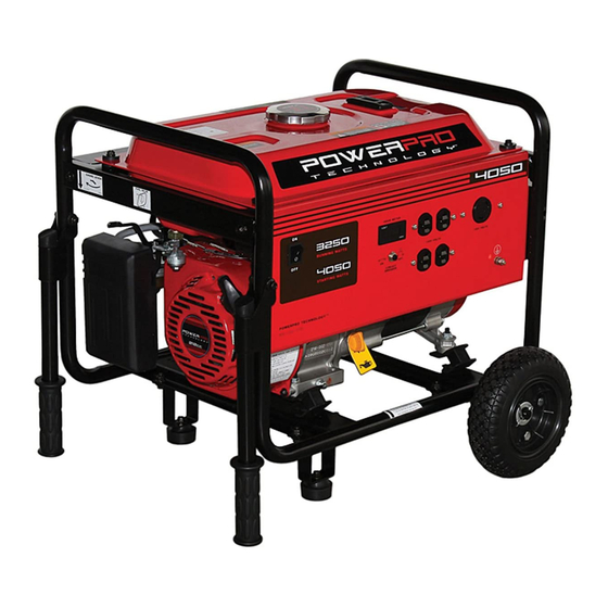
FEATURES
4050 Starting Watt Output
3250 Running Watt Output
2-120 Volt Duplex Receptacles
1-120 Volt Twist Lock Receptacle
Low Oil Automatic Shutoff
Circuit Breaker for Overload Protection
3.1 Gallon Fuel Tank Capacity
Spark Arrester
Digital Hour Meter
Mobility Kit included
Meets EPA Emission Standards
MODEL 4050
7.0 HP Generator
Item # 56405
Owner's Manual
DO NOT RETURN TO STORE
Questions? Problems?
Please call our customer help line:
(800) 232-1195
M-F 8-5 CST
Advertisement
Table of Contents

Subscribe to Our Youtube Channel
Related Manuals for PowerPro Technology 4050

Summary of Contents for PowerPro Technology 4050
- Page 1 Questions? Problems? Please call our customer help line: (800) 232-1195 M-F 8-5 CST FEATURES 4050 Starting Watt Output 3250 Running Watt Output 2-120 Volt Duplex Receptacles 1-120 Volt Twist Lock Receptacle Low Oil Automatic Shutoff Circuit Breaker for Overload Protection 3.1 Gallon Fuel Tank Capacity...
-
Page 3: Generator Identification
GENERATOR IDENTIFICATION (800) 232- For information and questions, please contact the Customer Service Help Line by calling 1195 . Certain information will be requested by the Customer Service Representative and to facilitate that, please fill in the information below. Refer to the illustration below for the location of Serial Number. Record generator information in the spaces provided below. -
Page 4: Table Of Contents
TABLE OF CONTENTS GENERATOR IDENTIFICATION ....................i SERVICE RECORD .........................i INTRODUCTION ..........................1 SAFETY INFORMATION......................2 GENERAL SAFETY PROCEDURES ...................3 IMPORTANT SAFETY INSTRUCTIONS ...................5 PACKAGE CONTENTS .........................7 GENERATOR COMPONENTS.....................8 ASSEMBLY………………………………………………………………………………………..9 GENERATOR PREPARATION ....................9 Using the Generator for the First Time ..................9 Step 1 - Fill Oil .........................10 Step 2- Add Gasoline........................11 Step 3- Ground the Generator....................12 STARTING THE GENERATOR ....................13... -
Page 5: Introduction
INTRODUCTION Thank You for Purchasing a Powerpro Technology Product. This manual provides information regarding the safe operation and maintenance of this product. Every effort has been made to ensure the accuracy of the information in this manual. Powerpro Technology reserves the right to change this product and specifications at any time without prior notice. -
Page 6: Safety Information
SAFETY INFORMATION Before operating this generator read and observe all warnings, cautions, and instructions on this sheet, on the generator, and in the Owner’s Manual. NOTE: The following safety information is not meant to cover all possible conditions and situations that may occur. Read the entire Owner’s Manual for safety and operating instructions. -
Page 7: General Safety Procedures
GENERAL SAFETY PROCEDURES For any questions regarding the hazard and safety notices listed in this manual or on the (800) 232-1195 M-F 8-5 CST product, please call before using the generator. DANGER : CARBON MONOXIDE. Using a generator indoors CAN KILL YOU IN MINUTES. - Page 8 WARNING : This generator produces powerful voltage, which can result in electrocution. ALWAYS ground the generator before using it (see the “Ground the Generator” portion of the “GENERATOR PREPARATION” section). Generator should only be plugged into electrical devices, either directly or with an extension cord.
-
Page 9: Important Safety Instructions
IMPORTANT SAFETY INSTRUCTIONS SAVE THESE INSTRUCTIONS – This manual contains important instructions for Powerpro Technology 4050 generator that should be followed during installation and maintenance of the generator. Generators vibrate in normal use. During and after the use of the generator, inspect the generator as well as extension and power supply cords connected to it for damage resulting from vibration. - Page 10 In addition to the previous safety notices, please become familiar with the safety and hazard markings on the generator.
-
Page 11: Package Contents
PACKAGE CONTENTS Your generator comes with the items listed below. Please check to see that all of the following items are included with your generator. (800) 232-1195 If there are any damaged or missing items, please call M-F 8-5 CST for customer service. -
Page 12: Generator Components
GENERATOR COMPONENTS Please familiarize yourself with the locations and functions of the various components and controls of your generator. (1)Air Cleaner- A removable, cleanable, sponge- (10) Ground Terminal- Connect grounding wires here like element that limits the amount of dirt pulled to properly ground unit. -
Page 13: Assembly
ASSEMBLY Step 1 – Wheel Installation 1. Blocking up the muffler side of the generator, assemble the axle to the frame. 2. Slide the wheel and washer onto the axle, with the offset of the wheel hub against the frame. 3. -
Page 14: Step 1 - Fill Oil
Step 1 - Fill Oil The generator is shipped without oil. User must add the proper amount of oil before operating the generator for the first time. The oil capacity of the engine crankcase is 20 fluid oz. Select good quality detergent oil bearing the American Petroleum Institute (API) service classifications SJ, SL, or SM. -
Page 15: Step 2- Add Gasoline
Gasoline can age in the tank and make it hard to start up the generator in the future. Never store generator for extended periods of time with fuel in the tank. Model number 4050 Fuel tank 12 L (3.1 gallons) -
Page 16: Step 3- Ground The Generator
Step 3- Ground the Generator WARNING: Failure to properly ground the generator can result in electrocution. Ground the generator by tightening the grounding nut against a grounding wire (see figure 5). A generally acceptable grounding wire is a No. 12 AWG (American Wire Gauge) stranded copper wire. -
Page 17: Starting The Generator
STARTING THE GENERATOR Before starting the generator, make sure you have read and performed the steps in the “GENERATOR PREPARATION” section of this manual. If you are unsure about how to (800) 232-1195 M-F 8-5 CST perform any of the steps in this manual please call customer service. -
Page 18: Subsequent Starting Of The Generator
To start your generator, perform the following steps: 1. No electrical devices should be connected to the generator during starting. Devices can make it difficult for the engine to start. 2. Check that the generator is properly grounded (see “Ground the Generator”). 3. -
Page 19: Step 1- Check The Oil
Step 1- Check the Oil Oil consumption is normal during generator usage. The generator is equipped with a low-oil shutoff to protect it from damage. The oil level in the engine should be checked before each use to ensure that the engine crankcase contains sufficient lubricant. To check or add oil, follow these steps: 1. -
Page 20: Using The Generator
Model Number Running Wattage Starting Watt 4050 3250 4050 Figure 9- generator wattage by model number. The total running wattage requirement of the electrical devices connected to the generator should not exceed the running wattage of the generator itself. - Page 21 If these specifications are not available, you may estimate the Watts required by your device using the chart in figure 10. When the running wattage requirement of each electrical device has been determined, add these numbers to find the total running wattage needed. If this number exceeds the running wattage of the generator, DO NOT connect all these devices.
- Page 22 1. Plug in each electrical device with the device turned off. NOTE: Be sure to attach appliances to the correct receptacles (outlets). Connect standard 120 Volt, single phase, 60 Hz loads only to the 120 Volt receptacles. Connect 120 Volt, single phase, 60Hz loads with a NEMA L5-30 plug only to the 120 Volt receptacle See Figure 11 for a depiction of each of these receptacles.
-
Page 23: Stopping The Generator
STOPPING THE GENERATOR Procedure to Stop Generator NOTE: Stopping the motor or unplugging cords from the generator while it is supplying power to devices will possibly damage the voltage regulator and result in low or no power output until the voltage regulator is replaced. -
Page 24: Maintenance / Care
MAINTENANCE / CARE Proper routine maintenance of your generator will help prolong the life of your machine. Please perform maintenance checks and operations according the schedule in figure 13. If you have questions about any of the maintenance procedures listed in this manual, please call (800) 232-1195 M-F 8-5CST. -
Page 25: Changing/ Adding Oil
Figure 14- Checking the oil Changing/ Adding Oil Change the oil according to the maintenance schedule in figure 13. Change the oil when the engine is warm. This will allow for complete drainage. Change oil more often if operating under heavy load or high ambient temperatures. -
Page 26: Air Cleaner Maintenance
Air Cleaner Maintenance Routine maintenance of the air cleaner helps maintain proper air flow to the carburetor. Check that the air cleaner is free of excessive dirt. 1. Unhinge the clasps at the top and bottom of the air cleaner cover (see figure 17). 2. -
Page 27: Spark Plug Maintenance
Spark Plug Maintenance The spark plug is important for proper engine operation. A good spark plug should be intact, free of deposits, and properly gapped. To inspect the spark plug: 1. Pull on the spark plug cap to remove it. 2. -
Page 28: Storage / Transport Procedures
STORAGE / TRANSPORT PROCEDURES CAUTION: Never place any type of storage cover on the generator while it is still hot. If the generator is being stored for short periods of time (30 – 60 days), add stabilized fuel to the fuel tank until full. -
Page 29: Specifications
SPECIFICATIONS Generator Running Wattage 3250 W Starting Wattage 4050W Rated Voltage 120 V Rated Amperage Rated Frequency 60 Hz Phase Single Dimensions(in) length= 23.3 width= 18.3 height= 18 (without mobility kit) Weight 114 lbs Engine 4-stroke OHV single cylinder with forced air Engine type cooling system Ignition system... -
Page 30: Troubleshooting
TROUBLESHOOTING IMPORTANT: If trouble persists please call our customer help line at (800) 232-1195 M-F 8-5 Central Time. Problem Cause Solution Engine switch is set to "OFF". Set engine switch to "ON". Fuel valve is turned to "OFF". Turn fuel valve to "ON" position. Choke is open. -
Page 31: Exploded View And Parts List
ENGINE EXPLODED VIEW AND PARTS LIST... - Page 32 ITEM DESCRIPTION ITEM DESCRIPTION CYLINDER HEAD ASSEMBLY EXHAUST VALVE SPRING SEAT CYLINDER HEAD SUBASSEMBLY VALVE CAP IN VALVE GUIDE SEAL GUIDE EX VALVE GUIDE VALVE TAPPET VALVE GUIDE CIRCLIP VALVE LIFTER INTAKE STUD LIFTER GUIDE EXHAUST STUD VALVE ADJUSTING BOLT CYLINDER HEAD GASKET VALVE ROCKER CYLINDER HEAD COVER...
- Page 33 ITEM DESCRIPTION ITEM DESCRIPTION FLOAT GASKET BOLT AIR CLEANER ASSEMBLY STOP ENGINE WIRE ELEMENT ASSEMBLY REGULATING ARM ELEMENT 1 ELEMENT 2 REGULATING BOLT AIR CLEANER COVER GOVERNOR SPRING BOLT GOVERNOR ROD AIR CLEANER ELEMENT BRACKET SMALL GOVERNOR SPRING AIR CLEANER ELEMENT GASKET THROTTLE CONTROL ASSEMBLY AIR CLEANER BASE BOLT...
- Page 34 GENERATOR EXLODED VIEW AND PARTS LIST...
- Page 35 ITEM DESCRIPTION ITEM DESCRIPTION ENGINE ASSEMBLY RUBBER FOOT MUFFLER ASSEMBLY SCREW MUFFLER GUIDE CROSSPIECE BOLT SCREW BOLT BRACKET FRAME RUBBER PAD BOLT FOOT BRACKET EXHAUST OUTLET GASKET RUBBER FOOT ASSEMBLY BOLT RUBBER SEAT EXHAUST PIPE BOLT FUEL TANK HANDLE FUEL FILTER HANDLE GRIP FUEL CAP CONTROL PANEL...
-
Page 36: Wiring Diagram
WIRING DIAGRAM... - Page 37 NOTES:...
-
Page 38: Warranty Statement
Power Pro Technology along with a copy of the receipt. The information is required to process warranty claims. PowerPro Technology™ will repair or replace, at its discretion, any part that is proven to be defective in materials or workmanship under normal use during the two (2) year warranty period.
Need help?
Do you have a question about the 4050 and is the answer not in the manual?
Questions and answers