Table of Contents
Advertisement
Quick Links
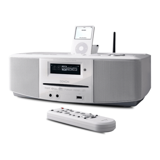
MODEL
S-52
S-52 DAB
MODEL
S-32
For purposes of improvement, specifications and
●
design are subject to change without notice.
Please use this service manual with referring to the
●
operating instructions without fail.
Some illustrations using in this service manual are
●
slightly different from the actual set.
SERVICE MANUAL
WIRELESS NETWORK CD MUSIC SYSTEM
WIRELESS NETWORK MUSIC SYSTEM
Denon Brand Company, D&M Holdings lnc.
JP
E3
E2
JP
E3
E2
注 意
サービスをおこなう前に、このサービスマニュアルを
必ずお読みください。本機は、火災、感電、けがなど
に対する安全性を確保するために、さまざまな配慮を
おこなっており、また法的には「電気用品安全法」に
もとづき、所定の許可を得て製造されております。
従ってサービスをおこなう際は、これらの安全性が維
持されるよう、このサービスマニュアルに記載されて
いる注意事項を必ずお守りください。
本機の仕様は性能改良のため、予告なく変更すること
●
があります。
補修用性能部品の保有期間は、製造打切後 8 年です。
●
修理の際は、必ず取扱説明書を参照の上、作業を行っ
●
てください。
本文中に使用しているイラストは、説明の都合上現物
●
と多少異なる場合があります。
Ver. 4
Please refer to the
MODIFICATION NOTICE.
EK
E2A E1C E1K EUT
EK
E2A E1C E2K EUT
X0360 V.04 DE/CDM 0712
Advertisement
Table of Contents

Related Manuals for Denon S-52


Summary of Contents for Denon S-52
- Page 1 Please use this service manual with referring to the ● 修理の際は、必ず取扱説明書を参照の上、作業を行っ ● operating instructions without fail. てください。 Some illustrations using in this service manual are ● 本文中に使用しているイラストは、説明の都合上現物 ● slightly different from the actual set. と多少異なる場合があります。 Denon Brand Company, D&M Holdings lnc. X0360 V.04 DE/CDM 0712...
- Page 2 S-52/S-52DAB/S-32 SAFETY PRECAUTIONS The following check should be performed for the continued protection of the customer and service technician. LEAKAGE CURRENT CHECK Before returning the unit to the customer, make sure you make either (1) a leakage current check or (2) a line to chassis resistance check.
- Page 3 S-52/S-52DAB/S-32 DIMENSION S-52/S-32...
-
Page 4: Wire Arrangement
S-52/S-52DAB/S-32 WIRE ARRANGEMENT ワイヤー整形図 If wire bundles are untied or moved to perform adjustment or 調整や部品の交換等により、ワイヤー類の結束をはずしたり移 parts replacement etc., be sure to rearrange them neatly as 動させた場合には、それらの作業が完了した時点でワイヤーの they were originally bundled or placed afterward. 整形をおこなってください。正しく整形されてないとノイズ発 Otherwise, incorrect arrangement can be a cause of noise 生の原因となることがあります。... - Page 5 S-52/S-52DAB/S-32 2. SIDE BRACKET(R) 2. SIDE BRACKET(R) 部 ④ Fasten the CY091 9P PH- PH SHIELD CORD on the H/P ④ H/P PORTBLE IN UNIT の CY091 9P PH- PH SHIELD CORD を コードホルダーで SIDE BRACKET (R) に固定する。 PORTBLE IN UNIT to the SIDE BRACKET (R) with a cord holder.
- Page 6 S-52/S-52DAB/S-32 4. FERRITE CLAMP102010N 4. FERRITE CLAMP102010N 部 ⑦ Coil and lock the primary side code of the power transformer ⑦ FERRITE CLAMP を開いた状態でパワートランスの一次側 with FERRITE CLAMP opened, then paste the EMIFILTER コードを一回巻き付けてロックし、EMIFILTER CUSHION を CUSHION to outer. 外周に貼る。 ⑧ Fasten the FERRITE CLAMP to the EMIFILTER CUSHION ⑧...
- Page 7 S-52/S-52DAB/S-32 DISASSEMBLY 各部のはずしかた (Follow the procedure below in reverse order when reassem- (組み立てるときは、逆の順序でおこなってください。 ) bling.) 1. BOTTOM COVER & SPEAKER BLOCK 1. BOTTOM COVER & SPEAKER BLOCK (1) Remove the 2 screws 107 on the bottom side. (1) 底面側からの 107 のねじ2本をはずす。...
-
Page 8: Speaker Unit
S-52/S-52DAB/S-32 2. SPEAKER UNIT 2. SPEAKER UNIT (1) Remove the 4 screws 109 fixing the SPEAKER BOX. (1) SPEAKER BOX を固定している、109 のねじ4本をはず (Both left and right) す。 (左右同じ) (2) Remove the wire soldered to the SPEAKER terminal. (2) SPEAKER 端子に半田付けしてあるワイヤーをはずす。... - Page 9 S-52/S-52DAB/S-32 3A.CD MECHA BLOCK(S-52) 3A.CD MECHA BLOCK(S-52) (1) Remove the 7 screws 105 and the 1 screw 104. (1) 105 のねじ 7 本 と 104 のねじ 1 本をはずす。 (2) 104 のねじ4本をはずす。 (2) Remove the 4 screws 104. (3) H/P PORTABLE IN UNIT の [CY091] から 9P PH-PH (3) Disconnect the 9P PH-PH SHIELD CORD from the SHIELD CORD をはずす。...
- Page 10 S-52/S-52DAB/S-32 (5) Disconnect the 9P/5P PH-PH CON.CORD in the direc- (5) 9P/5P PH-PH CON. CORD をそれぞれ矢印方向に引き出 tion of each the arrow. す。 (6) CD MECHA BLOCK を図のように持ち上げて MAIN UNIT (6) Lift up the CD MECHA BLOCK as shown in the photo and の...
-
Page 11: Main Chassis
S-52/S-52DAB/S-32 3B.MAIN CHASSIS(S-32) 3B.MAIN CHASSIS(S-32) (1) Remove the 8 screws 105. (1) 105 のねじ 8 本をはずす。 (2) 104 のねじ 2 本をはずす。 (2) Remove the 2 screws 104. (3) H/P PORTABLE IN UNIT の [CY091] から 9P PH-PH (3) Disconnect the 9P PH-PH SHIELD CORD from the SHIELD CORD をはずす。... - Page 12 S-52/S-52DAB/S-32 (4) Disconnect the 9P PH-PH SHIELD CORD in the direction (4) 9P PH-PH SHIELD CORD を矢印 A 方向に引き出す。 of the arrow A. (5) MAIN CHASSIS を矢印 B 方向にはずす。 (5) Disconnect the MAIN CHASSIS in the direction of the ar- row B.
- Page 13 S-52/S-52DAB/S-32 4. 1U-3851 CD ROM UNIT(S-52) 4. 1U-3851 CD ROM UNIT (S-52) (1) Remove each 2 screws D and E, then detach the MAIN (1) D のねじ 2 本と E のねじ2本をはずしてから、MAIN CHASSIS and the MECHA BRACKET in the direction of CHASSIS と...
- Page 14 S-52/S-52DAB/S-32 (3) Disconnect the 2P, 3P, 4P Wire and the FFC, then re- (3) 2P、3P、4P ワイヤー及び FFC をはずし、E のねじ2本 move the 2 screws E. をはずす。 3P Wire 4P Wire 2P Wire (4) Stand the CD ROM UNIT and disconnect the FFC.
-
Page 15: Main Block
S-52/S-52DAB/S-32 5. MAIN BLOCK 5. MAIN BLOCK (1) Remove the 5 screws 106 and the 5 screws 108 on the (1) 後面側からの 106 のねじ 5 本と 108 ねじ5本をはずす。 rear. (2) MAIN UNIT の [CX101] から 10P ZH-JB CON.CORD をは ずす。... - Page 16 S-52/S-52DAB/S-32 (4) Disconnect the 16P FPC from the [CX161] on the MAIN (4) MAIN UNIT の [CX161] から 16P FPC をはずす。 UNIT. (5) MAIN UNIT の [CX064] から 6P ZH-ZH CON.CORD をは (5) Disconnect the 6P ZH-ZH CON.CORD from the [CX064] ずす。...
- Page 17 S-52/S-52DAB/S-32 6A. 1U-3854 STANDBY TRANS UNIT 6A. 1U-3854 STANDBY TRANS UNIT (for JP/E3/E2) (JP/E3/E2) (1) Remove the 1 screw 113 and the 1 screw 105 on the rear. (1) 113 のねじ 1 本と 105 のねじ1本をはずす。 (2) Disconnect the 5P PH-PH CON.CORD from the [CX051] (2) STANDBY TRANS UNIT の...
- Page 18 S-52/S-52DAB/S-32 6B. 1U-3854 STANDBY TRANS UNIT(for EK) 6B. 1U-3854 STANDBY TRANS UNIT (EK) (1) Disconnect the 8P PH-PH SHIELD CORD from the (1) 1U-3847-2 の [CY081] から 8P PH-PH SHIELD CORD をは ずす。 [CY081] on 1U-3847-2. (2) Remove the 2 side screws 117, then detach the DAB (2) 側面の...
-
Page 19: Power Trans
S-52/S-52DAB/S-32 7. POWER TRANS 7. POWER TRANS (1) Remove the 4 screws 105 on the rear. (1) 後面側から、105 のねじ 4 本をはずす。 8. 1U-3847-1 POWER AMP UNIT 8. 1U-3847-1 POWER AMP UNIT (1) POWER AMP UNIT の [CY062] から 6P PH-PH SHIELD (1) Disconnect the 6P PH-PH SHIELD CORD from the CORD をはずす。... - Page 20 S-52/S-52DAB/S-32 (5) Remove the 2 inside screws 104 and the 2 rear screws (5) 内側の 104 のねじ 2 本と、後面側から 105 のねじ2本 105. をはずす。 9. 1U-3859-1 POWER UNIT 9. 1U-3859-1 POWER UNIT (1) POWER UNIT の [CY111] から 11P PH-PH CON.CORD を...
- Page 21 る 104 のねじ2本をはずす。 of the side bracket is fixed. (2) WIRE CLAMPER 1 箇所をカットし、取り除く。(S-52 の (2) Cut off the 1 WIRE CLAMPER and remove.(S-52 only) み ) (3) Disconnect the 16P CON.CORD from the [CX161] on the (3) MAIN UNIT の [CX161] から 16P CON.CORD をはずす。...
- Page 22 S-52/S-52DAB/S-32 (12) Disconnect the 1P SAN EH CON.CORD from CX021 on (12) POWER AMP UNIT の [CX021] から 1P SAN EH CON. the Power Amp Unit, then pull out in the direction of the CORD をはずし、矢印方向に引き抜く。 arrow. 1P SAN EH CON. CORD (13A) 105 のねじ...
-
Page 23: Ffc Cable
S-52/S-52DAB/S-32 (15) Remove the 6 screws 105 and the 2 screws 104, the 2 (15) 105 のねじ 6 本と、104 のねじ 2 本、118 の 3W2 枚 washers 118. をはずす。 (16) Disconnect the 15P FFC CABLE from the AM FM TUN- (16) AM FM TUNER から、15P FFC CABLE をはずす。(S- ER.(S-52JP/E2/EK,S-32E2/E3) -
Page 24: Rotary Knob
S-52/S-52DAB/S-32 11.ROTARY KNOB 11.ROTARY KNOB (1) The SNAP FIT is bent from the back of the CABINET in (1) CABINET 裏側面より、SNAP FIT を矢印①方向にたわま the direction of the arrow ① . せる。 (2) The ROTARY KNOB RING is rotated in the direction of (2) ROTARY KNOB RING を矢印②方向に回転させて、表面... - Page 25 S-52/S-52DAB/S-32 DIAGNOSTICS OF OPTICAL PICKUP 光ピックアップの故障診断とトラバース AND REPLACING TRAVERSE UNIT ユニットの交換 Make failure diagnostics of the Optical Pickup as follows. 次の順序で故障診断を行ってください。 If the laser drive current (Iop) becomes more than 1.5 times of レーザー駆動電流 Iop 値が初期値の 1.5 倍以上になっている the initial value, the Optical Pickup should be replaced.
- Page 26 S-52/S-52DAB/S-32 1. Iop checked Method 1. Iop 値の確認方法 Select the laser ON/OFF (CD) mode of the test mode, and レーザー駆動電流を確認する場合は、テストモードのレー check the lop value of CD laser. ザー ON/OFF (CD) モードを選択して、CD レーザーの lop (See page 32 for test mode.) 値を確認します。...
- Page 27 S-52/S-52DAB/S-32 4. Rewriting the default value of the laser 4. レーザー電流初期値の書き換え方法 current レーザー電流の初期値を書き換えるには、 CD レーザー電流 が表示されている時に ボタンを 5 秒以上押し、次に To rewrite the default value of the laser current, press the ボタンまたは ボタンを押して T23 を選択しま button for at least 5 seconds while the CD laser current す。...
-
Page 28: How To Replace Traverse Unit
S-52/S-52DAB/S-32 HOW TO REPLACE TRAVERSE UNIT トラバースユニットの交換方法 (S-52,S-52ADB) (S-52,S-52DAB) Caution: The optical pickup can be damaged easily by 注意 : 光ピックアップは、人体に帯電した静電気等で静電 static electricity charged on human body. 破壊することがあります。光ピックアップ周辺を修 Take necessary anti-static measures when 理する際は、必要な静電対策を行ってください。 repairing around the optical pickup. (組み立てるときは、逆の順序でおこなってください。 )... - Page 29 S-52/S-52DAB/S-32 2. Traverse Unit disassembly 2. トラバースユニットのはずしかた (1) Solder the short-circuit. (1) 半田付けショートをおこないます。 (2) Remove 4 screws C. (2) ねじ C 4 本をはずします。 (3) Disconnect FFC from the Pick Up. (3) ピックアップから FFC をはずします。 Solder to short-circuit (4) Lift the Traverse Assy and disconnect FFC.
-
Page 30: Service Mode
S-52/S-52DAB/S-32 SERVICE MODE サービスモードについて 1. Initial Setting Mode 1. イニシャルモード 1.1. Preparation 1.1. 準備 (1) Equipment used: None (1) 使用機器:無 (2) Unit setting: No spec other than the following procedure. (2) 本体設定:下記手順以外規定無。 1.2. Procedure 1.2. 手順 ● SYSTEM ● システム... - Page 31 S-52/S-52DAB/S-32 3. Heat Run Mode (S-52) 3. ヒートランモード (S-52) 3.1. preparation 3.1. 準備 (1) Equipment used: CD (1) 使用機器:CD (2) Unit setting : No spec other than the following procedure. (2) 本体設定:下記設定以外規定無。 3.2. procedure 3.2. 手順 ※ Perform heat run of the CD.
- Page 32 S-52/S-52DAB/S-32 4. Test mode (S-52) 4. テストモード (S-52) 4.1. Entering the test mode 4.1. テストモードの設定 To set the test mode, press the RETURN button before pressing the button in the heat run mode.Not insert the disc. テストモードの設定はヒートランモード時に ボタンを押す前に RETURN ボタンを押すことでおこなう。 ディスクは挿入して...
- Page 33 S-52/S-52DAB/S-32 4.3. Setting the mode 4.3. モードの確定 With the mode selected, press the button to set that mode. モードを選択してある状態で ボタンを押すとモードを確定する。 ① In the laser on/off (CD) mode, laser on/off control is executed and the laser current is displayed. ①レーザー ON/OFF(CD) モードの場合、レーザーの ON/OFF 制御を実行し、レーザー電流を表示する。...
- Page 34 S-52/S-52DAB/S-32 4.4. Change within the mode 4.4. モード内での変更 Changes within modes are made by pressing the buttons while the mode is set. モードを確定してある状態で ボタンまたは ボタンを押すとモード内での変更をおこなう。 ① In the laser on/off mode, laser on/off control is executed and the laser current is displayed.
- Page 35 S-52/S-52DAB/S-32 4.5. Execution of trace mode (error rate display) (See "Table 2 - Trace mode details") 4.5. トレースモード ( エラーレート表示 ) の実行 ( 表 2 トレースモード詳細 参照) Trace will be performed if the button is pushed after choosing operation. 動作を選択した後、...
- Page 36 S-52/S-52DAB/S-32 5. Product Mode 5. プロダクトモード 5.1. Setting the product mode 5.1. プロダクトモードの設定 ※ The TUNER and AVAMP set to the puroduct mode. ※ TUNER,AVAMP をプロダクトモードにする。 (1) Pressing the and SNOOZE buttons simultaneously, plug the AC cord into a power outlet. This sets the puroduct mode.
-
Page 37: Troubleshooting
S-52/S-52DAB/S-32 TROUBLE SHOOTING トラブルシューティング ● ADV-S52 ● ADV-S52 トラブルシューティング 1. LCD doesn't display 1. LCD表示せず (1) Check the Set-up process of System -COM and BF(DSP) (1) システムμ-COMとBF(DSP)立ち上がりチェック工程 Check Power Supply Voltages for System uCOM. システムマイコン用電源電圧確認 1U-3846-1(MAIN UNIT) Check Soldering. 1U-3846-1(MAIN UNIT) 半田付けを確認... - Page 38 ・ [LCD_P],[LCD_BACK_LIGHT] ・ 1U-3847-3(REMOTE SENSOR/LCD UNIT). O.K. O.K. 終了 2. CD再生せず(S-52,S-52DABのみ) 2. CD doesn't playback(S-52,S-52DAB only) (1) Check the Set-up process of BF(DSP) and FE Drive (1) BF(DSP)とFEドライブ立ち上がりチェック工程 Check Power Supply Voltages for FE Drive. FE ドライブ用電源電圧確認 1U-3859-1(POWER UNIT) Check Soldering.
- Page 39 S-52/S-52DAB/S-32 3. 音声出力せず、ノイズ発生 3. No Sound,Noise generated (1) CD PLAY(S-52,S-52DAB only) (1) CD 再生時(S-52,S-52DABのみ) Check Power Supply Voltages for AUDIO. オーディオ用電源電圧確認 1U-3846-1(MAIN UNIT) Check Soldering. 1U-3846-1(MAIN UNIT) 半田付けを確認 +12V_A1 1U-3859-1(POWER UNIT). ・ +12V_A1 ・ 1U-3859-1(POWER UNIT). CX111 on MAIN UNIT.
- Page 40 S-52/S-52DAB/S-32 Check Analog Audio Data output from CODEC CODECからAMPへのアナログオーディオデータ出力確認 to AMP. 1U-3846-1(MAIN UNIT) Check Soldering. 1U-3846-1(MAIN UNIT) 半田付けを確認 [IC300] output and [IC301] input [IC300]:40,41pin on MAIN UNIT. ・ [IC300] output and [IC301] input ・ [IC300]:40,41pin on MAIN UNIT. [Lch],[Rch] [IC301] on MAIN UNIT.
- Page 41 S-52/S-52DAB/S-32 (2) AM/FM TUNER-in(S-52E2JP,S-52DAB,S-32 only) (2) AM/FM TUNER入力(S-52E2JP,S-52DAB,S-32のみ) Check Power Supply Voltages for AM/FM TUNER. AM/FMチューナー用電源電圧確認 1U-3846-1(MAIN UNIT) Check Soldering. 1U-3846-1(MAIN UNIT) 半田付けを確認 +12V_A TR304,TR306,TR307,TR308 ・ +12V_A ・ TR304,TR306,TR307,TR308 +5V_A CX151 on MAIN UNIT. ・ +5V_A CX151 on MAIN UNIT.
- Page 42 S-52/S-52DAB/S-32 (4) IPOD-IN (4) IPOD入力 Check Power Supply Voltages for IPOD. IPOD用電源電圧確認 1U-3846-1(MAIN UNIT) Check Soldering. 1U-3846-1(MAIN UNIT) 半田付けを確認 F/W PWR+:+12V OK? TR311,TR314,CX131 on MAIN UNIT. ・ F/W PWR+:+12V OK? ・ TR311,TR314,CX131 on MAIN UNIT. +5V_D1 ・ +5V_D1 O.K. O.K.
- Page 43 S-52/S-52DAB/S-32 (6) XM RADIO-in(S-52E3 only) (6) XM RADIO入力(S-52E3のみ) Check Power Supply Voltages for XM Ready circuit. XM Ready回路用電源電圧確認 1U-3846-1(MAIN UNIT) Check Soldering. 1U-3846-1(MAIN UNIT) 半田付けを確認 +5.3V_XM IC108,CY111 on POWER UNIT. ・ +5.3V_XM ・ IC108,CY111 on POWER UNIT. +3.3V_XM IC711,CX111,CX081 on MAIN UNIT.
- Page 44 S-52/S-52DAB/S-32 Check Digital Audio Data Clock from Clock selector Check Soldering. クロックセレクタからBF/CODECへのデジタルオーディオ 半田付けを確認 to BF/CODEC. 1U-3846-1(MAIN UNIT) [IC305]:8,6,3pin on MAIN UNIT. データ用クロックの確認。1U-3846-1(MAIN UNIT) ・ [IC305]:8,6,3pin on MAIN UNIT. [IC305]output and [IC101]/[IC300]input: [IC300]:24,11,10pin on MAIN UNIT. ・ [IC305]output and [IC101]/[IC300]input: ・ [IC300]:24,11,10pin on MAIN UNIT.
- Page 45 S-52/S-52DAB/S-32 (8) ETHERNET-in (8) ETHERNET入力 Check Power Supply Voltages for DM850(IC501) DM850(IC501)とPHY(IC504)用電源電圧確認 and PHY(IC504). 1U-3846-1(MAIN UNIT) Check Soldering. 1U-3846-1(MAIN UNIT) 半田付けを確認 +3.3V_E1 IC511,IC512 on MAIN UNIT. ・ +3.3V_E1 ・ IC511,IC512 on MAIN UNIT. +1.8V_E1 [IC701]:67pin on MAIN UNIT. ・ +1.8V_E1 ・...
- Page 46 S-52/S-52DAB/S-32 Check Digital Audio Data output from DM850 DM850からCODECへのアナログオーディオデータ to CODEC. 1U-3846-1(MAIN UNIT) Check Soldering. 出力確認。1U-3846-1(MAIN UNIT) 半田付けを確認 [DM850] output and [IC300] input [IC501]:39pin,R198 on MAIN UNIT. ・ [DM850] output and [IC300] input ・ [IC501]:39pin,R198 on MAIN UNIT. [SPDIF_ETHER] [IC300]:4pin on MAIN UNIT.
- Page 47 S-52/S-52DAB/S-32 (10) WiFi-in (10) WiFi入力 Check Power Supply Voltages for WiFi. WiFi用電源電圧確認 and PHY(IC504). 1U-3846-1(MAIN UNIT) Check Soldering. 1U-3846-1(MAIN UNIT) 半田付けを確認 +3.3V_E1 IC511 on MAIN UNIT. ・ +3.3V_E1 ・ IC511,IC512 on MAIN UNIT. ・ +1.8V_E1 ・ [IC701]:67pin on MAIN UNIT.
-
Page 48: Block Diagrams
S-52/S-52DAB/S-32 BLOCK DIAGRAMS S-52,S52DAB S52 SYSTEM PART BLOCK DIAGRAM KEY/RC K8D3216UBC W9812G6GH K8D1716UBC W9812G6GH 32M Frash 128M SDRAM 16M Frash 128M SDRAM Broad Com WiFi Address/Data BUS Ad/Data BUS BD4727 Reset ADSP-BF532 DM-850E M30879FKBGP X'TAL RTL8201CP ATAPI Control 24.576 µ COM... - Page 49 S-52/S-52DAB/S-32 S-32 S32 SYSTEM PART BLOCK DIAGRAM KEY/RC K8D3216UBC W9812G6GH 128M SDRAM K8D1716UBC W9812G6GH 32M Frash 16M Frash 128M SDRAM Broad Com WiFi Address/Data BUS Ad/Data BUS BD4727 Reset ADSP-BF532 DM-850E M30879FKBGP X'TAL RTL8201CP ATAPI Control 24.576 µ COM X,tal...
-
Page 50: Level Diagram
S-52/S-52DAB/S-32 LEVEL DIAGRAM ELECTRICAL VOLUME AMP TOSHIBA TA8216H... - Page 51 S-52/S-52DAB/S-32 SEMICONDUCTORS Only major semiconductors are shown, general semiconductors etc. are omitted to list. 主な半導体を記載しています。汎用の半導体は記載を省略しています。 1. IC’s DM850E (IC502)
- Page 52 S-52/S-52DAB/S-32 DM850E Pin Assignment by Pin Number Name Name Name Name VSSIO USBREF A[19] VSSIO AV0CLK VSSIOUSB A[2 0] VDDIO VDDIO VDDIOUSB A[2 1] A[5 ] AV0DATA[0] VDDUSBPLL NW E A[6 ] AV0DATA[1] VSSUSBPLL NCS[2] AV1DATA[0] AV0DATA[2] VSSIO NCS[1] AV1DATA[1]...
- Page 53 S-52/S-52DAB/S-32 ADSP-BF532 (IC101) 9 10 11 12 13 14 KEY : DDINT DDRTC DDEXT ROUT (Top View) ADSP-BF532 Ball Number Ball No. Signal Ball No. Signal Ball No. Signal Ball No. Signal VDDEXT DT0PRI SCAS DT0SEC TFS0 DATA12 PF10 DATA9...
- Page 54 S-52/S-52DAB/S-32 M30879FKBGP (IC701)
- Page 55 S-52/S-52DAB/S-32 M30879FKBGP Pin Description...
- Page 56 S-52/S-52DAB/S-32...
- Page 57 S-52/S-52DAB/S-32 AK4683EQ (IC300)
- Page 58 S-52/S-52DAB/S-32 AK4683WQ Pin Function...
- Page 59 S-52/S-52DAB/S-32...
-
Page 60: Printed Wiring Boards
S-52/S-52DAB/S-32 PRINTED WIRING BOARDS 1U-3846 MAIN P.W.B. UNIT (1/2) COMPONENT SIDE... - Page 61 S-52/S-52DAB/S-32 1U-3846 MAIN P.W.B. UNIT (2/2) FOIL SIDE...
- Page 62 S-52/S-52DAB/S-32 1U-3847 VIDEO P.W.B. UNIT (1/2) COMPONENT SIDE COMPONENT SIDE...
- Page 63 S-52/S-52DAB/S-32 1U-3847 VIDEO P.W.B. UNIT (2/2) FOIL SIDE FOIL SIDE...
- Page 64 S-52/S-52DAB/S-32 1U-3851 L.PWR/DISP P.W.B. UNIT (1/2) COMPONENT SIDE...
- Page 65 S-52/S-52DAB/S-32 1U-3851 L.PWR/DISP P.W.B. UNIT (2/2) FOIL SIDE...
- Page 66 S-52/S-52DAB/S-32 1U-3859 D.AMP/SMPS P.W.B. UNIT (1/2) COMPONENT SIDE...
- Page 67 S-52/S-52DAB/S-32 1U-3859 D.AMP/SMPS P.W.B. UNIT (2/2) FOIL SIDE FOIL SIDE...
-
Page 68: Note For Parts List
S-52/S-52DAB/S-32 NOTE FOR PARTS LIST 部品表について • Parts for which "nsp" is indicated on this table cannot be supplied. 1.部品表に "nsp" と記載されている部品は供給できません。 • When ordering of part, clearly indicate "1" and "I" (i) to avoid mis- 2.部品を発注する際は特に数字の " 1 " と英字の "I" との区別をはっき... -
Page 69: Parts List Of P.w.b. Unit
00D 262 3400 904 TPC6103 NOTE : When update Firmware, please IC111,112 00D 262 2640 901 SN74LV245APW-EL2 for S-52 confirm a last version in SDI. IC113 00D 262 2516 909 SN74LV32APW-EL2 +C for S-52 Use the service board after updating it. - Page 70 S-52/S-52DAB/S-32 Ref. No. Part No. Part Name Remarks Q'ty New IC707 00D 262 3742 905 F2621E-01 for S-52E3 IC708 00D 273 0492 902 SP8K3FU6TB for S-52E3 IC711 00D 262 2977 946 BA33BC0FP-E2 +REF for S-52E3/DABEK IC871 00D 263 0673 902...
- Page 71 +1005 C166 CK73F1E104ZT +1608 C167 CK73F1H103ZT +1608 C168-171 00D 254 4740 921 CE67W1C470MT(GV) C172,173 00D 257 2018 900 CS77B1A100MT(NOJ) C174 CK73F1E104ZT +1608 for S-52 C175-177 CK73F1E104ZT +1608 C178 CK73F1H103ZT +1608 C179 CK73B1H102KT +1608 C183 CK73F1E104ZT +1608 C184 CK73F1H103ZT +1608 C185,186...
- Page 72 S-52/S-52DAB/S-32 Ref. No. Part No. Part Name Remarks Q'ty New C325,326 00D 254 4740 976 CE67W1C100MT(GV) C327 CC73CH1H101JT +1608 C328 CK73F1H103ZT +1608 C329,330 CK73F1E104ZT +1608 C331 CC73CH1H561JT +1608 C332 CC73CH1E681JT +1608 C333 CC73CH1H561JT +1608 C334 CC73CH1E681JT +1608 C336,337 00D 254 4740 934...
- Page 73 CK73F1E104ZT +1608 C413 CK73B1H102KT +1608 C414,415 CK73F1H103ZT +1608 C501 CK73F1H103ZT +1608 C502 CK73B1H102KT +1608 C503 CK73F1H103ZT +1608 for S-52 C504 CK73B1H102KT +1608 for S-52 C505 CK73F1E104ZT +1608 C506-510 00D 257 0521 949 CK73B1A474KT C511-513 CK73F1E104ZT +1608 C514-517 CK73B1H102KT +1608 C700-702...
- Page 74 +1608 CC159 00D 254 4740 905 CE67W1C220MT(GV) CC160 CK73F1E104ZT +1608 CC161-164 RM73B--0R0KT +1608 CC165 CK73F1E104ZT +1608 for S-52 CC166 00D 254 4738 904 CE67W0J101MT(GV) for S-52 CC167,168 CK73F1E104ZT +1608 for S-52 CC169 00D 257 0039 907 CK73B0J106MT for S-52 CC174...
- Page 75 CC205-213 00D 257 5002 926 CC73CH1H100DT +1005 OTHERS PARTS GROUP CX051 5P PH CON BASE(TAPE) +REF CX054 5P PH CON BASE(TAPE) +REF for S-52 CX062 6P CONN.BASE(KR-PH) CX071 7P ZH-ZR CON.BASE-T for S-52E3/E2/DABEK,S-32E3/E2 CX081 8P PH CON.BASE(TAPE) for S-52DABEK CX091 9P CONN.BASE(KR-PH)
- Page 76 S-52/S-52DAB/S-32 1U-3847 POWER AMP/KEY P.W.B. UNIT ASS'Y Ref. No. Part No. Part Name Remarks Q'ty New SEMICONDUCTORS GROUP IC107 00D 399 1126 003 GP1UE261XKVF TR105,106 00D 269 0192 902 KRC102S-RTK/P (10K-10K) ZD102 00D 276 0683 943 UDZS3.6B-TE17 LD101,102 00D 393 9663 007...
- Page 77 S-52/S-52DAB/S-32 Ref. No. Part No. Part Name Remarks Q'ty New JK102 00D 204 8424 002 H/PHONE JACK S101-113 00D 212 5604 907 TACT SWITCH-TA(ALPS) S114 00D 212 1209 005 PUSH SWITCH S115 00D 212 0529 003 ROTARY ENCODER S116 00D 212 1209 005...
- Page 78 +REF D315 00D 276 0401 905 1SS133T77 (TAPE) D316-323 00D 276 0750 902 RB521S-30TE61 +REF ZD101 00D 276 0837 906 NSAD500F-T1B-A for S-52 ZD102 RM73B--0R0KT +2125 RESISTORS GROUP R515,516 00D 241 2171 907 RD14B2H4R7JT R102 00D 247 2024 913 RM73B--6041DT...
- Page 79 Part No. Part Name Remarks Q'ty New C147-149 00D 254 4708 905 CE04W1E221MT HB5(KY) C150 CK73F1H103ZT +1608 C200 00D 254 4533 934 CE04W0J221MT SMG/RE3 for S-52 C201-203 CK73F1E104ZT +1608 for S-52 C206 CK73F1E104ZT +1608 C207 CK73B1H102KT +1608 C208 CK73F1E104ZT +1608...
- Page 80 FUSE 1A T for S-52DABEK F103 00D 206 1035 054 FUSE 1.6A (T) for S-52JP FB100 00D 235 0147 909 E.FIL(BLM21PG221SN1)+2125 for S-52 FF100-103 FUSE CLIP(TAPE) FH100-103 FUSE CLIP(TAPE) JK103 00D 204 8714 000 USB CONNECTOR(TOPYANG BLACK) for S-52 JK203...
-
Page 81: Exploded View
S-52/S-52DAB/S-32 EXPLODED VIEW S-52/S-52DAB model only S-52/S-52DAB model only S-52/S-52DAB model only 4-10 4-11 4-12 S-52/S-52DAB model only ※For details on , refer to exploded view of CD mechanism unit. WARNING: Parts marked with this symbol have critical characteristics. Use ONLY replacement parts recommended by the manufacturer. -
Page 82: Parts List Of Exploded View
CABINET ASSY for S-52E2 CABINET ASSY for S-52DABEK CABINET ASSY for S-52JP CABINET ASSY for S-32E2 CABINET ASSY for S-32E3 CABINET for S-52 CABINET for S-32 FRONT CABINET for S-52 FRONT CABINET for S-32 WINDOW for S-52E2 WINDOW for S-52E3... - Page 83 KNOB(2P) B ASSY KNOB(2P) B BASE LED LENS 00D 113 2104 103 KNOB (ON/STBY) 00D 113 2105 005 KNOB (EJECT) for S-52 00D 113 2105 018 KNOB (EJECT) for S-32 00D 113 2106 208 KNOB(PLAY) 00D 113 2111 109 KNOB (3P)
-
Page 84: Bottom Cover
Part Name Remarks Q'ty New TOP BRACKET PWB BRACKET PROTECTION SHEET PUSH RIVET CORD HOLDER FGDVS202MS CD MECHA UNIT for S-52 MAIN CHASSIS for S-32 E2 LASER CAUTION for S-52E2/DABEK LABEL(A) for S-52E3 BOTTOM COVER 00D 461 1066 002 FELT... - Page 85 S-52/S-52DAB/S-32 Ref. No. Part No. Part Name Remarks Q'ty New NOISE INSULATE (BTM) for S-52 SCREWS 2.6X5 CBTS (S)-Z 2.6X8 CBTS (P)-Z 3X4 CBTS (S)-Z 3X6 CBTS(S)-Z 3X6 CBTS(S)-B 3X6 CBTS (S)-B 3X8 CBTS (P)-B 3X8 CBTS(B)-B 3X10 CBTS (P)-Z...
-
Page 86: Exploded View Of Cd Mechanism Unit
S-52/S-52DAB/S-32 EXPLODED VIEW OF CD MECHANISM UNIT WARNING: Parts marked with this symbol have critical characteristics. Use ONLY replacement parts recommended by the manufacturer. 印の部分は安全を維持するために重要 な部品です。従って交換時は必ず指定の 部品を使用してください。... -
Page 87: Parts List Of Cd Mechanism Unit(S-52)
S-52/S-52DAB/S-32 PARTS LIST OF CD MECHANISM UNIT(S-52) * 本表に "nsp" と記載されている部品は供給できません。 * Parts for which "nsp" is indicated on this table cannot be supplied. * 本表に記載されている部品は、補修用部品のため製品に使用している部品とは一部、形状、寸法などが異なる場合があります。 * The parts listed below are for maintenance only, might differ from the parts used in the unit in appearances or dimensions. -
Page 88: Packing View
S-52/S-52DAB/S-32 PACKING VIEW... -
Page 89: Parts List Of Packing & Accessories
S-52E3,S-32E3 00D 515 0918 607 SERVICE STATION LIST for S-52JP POLY COVER for ACCESSARY 00D 399 1121 008 REMOCON(RC1083) for S-52 00D 399 1123 006 REMOCON(RC1089) for S-32 BATTERY (UM-4) ASS 00D 231 1152 001 AM LOOP ANTENNA(S) for S-52E2/DABEK/JP,S-32E2/E3 00D 395 0026 005 FM ANT. -
Page 90: Wiring Diagrams
S-52/S-52DAB/S-32 WIRING DIAGRAMS S-32 Jumper 1U-3847-7 JOG ENCODER UNIT S32 WIRING DIAGRAM H/P OUT JACK Portable IN JACK iPod DOCK Connector 1U-3847-3 Jumper REMOTO SENSOR 1U-3847-4 1U-3847-5 1U-3847-6 /LCD UNIT 1U-3859-2 H/P PORTBLE IN UNIT KEY UNIT ALARM UNIT IPOD I/O UNIT... - Page 91 S-52/S-52DAB/S-32 S-52 Jumper 1U-3847-7 S52 WIRING DIAGRAM JOG ENCODER UNIT USB Connector JACK (S52 ONLY) H/P OUT JACK Portable IN JACK iPod DOCK Connector 1U-3847-3 REMOTO SENSOR 1U-3859-3 Jumper 1U-3847-4 1U-3847-5 1U-3847-6 /LCD UNIT 1U-3859-2 H/P PORTBLE IN UNIT KEY UNIT...
-
Page 92: Measuring Method And Waveforms
S-52/S-52DAB/S-32 MEASURING METHOD AND WAVEFORMS 各部の波形と測定方法 To check the waveforms on the FEP, the GND (-) probe of FEP 基板の波形チェックを行うためにはオシロスコープの the oscilloscope to “VHALF” point. GND(-) プローブを "VHALF" ポイントに接続します。 (Except for lnner SW, TRVSW) 注 意 NOTES 測定ディスク: CD/TCD-784 Measuring Disc: CD/TCD-784 (テストポイントとプローブ間に延長ワイヤを使用するの... - Page 93 S-52/S-52DAB/S-32 WAVEFORMS IU-3851 FEP Unit CD PLAY Disc : TCD-784 RF waveform SEARCH (INNER OUTER) ① ARF ② NARF ⑨ TRSDRV ⑩ ⑪ ⑨ 1 v RANGE 20 msec ⑩ RANGE .2 v ⑪ CD PLAY (INNER) CD LOADING PLAY ③...
-
Page 94: Iu-3846 Main Unit
S-52/S-52DAB/S-32 IU-3846 MAIN Unit Wave form 3 : CLOCK Waveform (12.288MHz) Wave form1: PWR_OFF_DET 50/60 Waveform 波形3:クロック波形 (12.288MHz) 波形1:停電検出50/60波形 CX051 5pin X301 (Refer to the SCHEMATIC DIAGRAMS 4/7) (Refer to the SCHEMATIC DIAGRAMS 3/7) (SCHEMATIC DIAGRAMS 4/7を参照) (SCHEMATIC DIAGRAMS 3/7を参照) Wave form 4 : A/D Waveform Wave form 2 : CLOCK Waveform (11.2896MHz) -
Page 95: Note For Schematic Diagram
S-52/S-52DAB/S-32 NOTE FOR SCHEMATIC DIAGRAM 配線図について WARNING: ! 印の部品は安全を維持するために重要な部品です。 従って交換時は必ず指定の部品を使用してください。 Parts marked with this symbol ! have critical characteristics. Use ONLY replacement parts recommended by the manufactur- 注) CAUTION: (1) 指定なき抵抗値は Ω、k は kΩ、M は MΩ を示す。 Before returning the unit to the customer, make sure you make (2) 指定なきコンデンサーの値は... - Page 96 SCHEMATIC DIAGRAMS (1/7) S-52 / S-52DAB / S-32 SIGNAL LINE SCHEMATIC DIAGRAMS (1/7) 1U-3846-1 MAIN UNIT(1/4) Note : [Sheet 1] : SCHEMATIC DIAGRAMS (1/7), 1U-3846 MAIN UNIT - BF block BF block [Sheet 2] : SCHEMATIC DIAGRAMS (2/7), 1U-3846 MAIN UNIT - ETHER/USB/WiFi block...
- Page 97 SCHEMATIC DIAGRAMS (2/7) S-52 / S-52DAB / S-32 Wifi ETHERNET SIGNAL LINE SCHEMATIC DIAGRAMS (2/7) 1U-3846-1 MAIN UNIT(2/4) Note : ETHER/USB/WiFi block [Sheet 1] : SCHEMATIC DIAGRAMS (1/7), 1U-3846 MAIN UNIT - BF block [Sheet 2] : SCHEMATIC DIAGRAMS (2/7), 1U-3846 MAIN UNIT - ETHER/USB/WiFi block...
- Page 98 SCHEMATIC DIAGRAMS (3/7) S-52 / S-52DAB / S-32 HD Analog iPod TUNER Portable In ETHERNET/Wifi/USB SIGNAL LINE SCHEMATIC DIAGRAMS (3/7) Note : [Sheet 1] : SCHEMATIC DIAGRAMS (1/7), 1U-3846 MAIN UNIT - BF block 1U-3846-1 MAIN UNIT(3/4) [Sheet 2] : SCHEMATIC DIAGRAMS (2/7), 1U-3846 MAIN UNIT - ETHER/USB/WiFi block...
- Page 99 SCHEMATIC DIAGRAMS (4/7) S-52 / S-52DAB / S-32 SIGNAL LINE SCHEMATIC DIAGRAMS (4/7) 1U-3846-1 MAIN UNIT(4/4) Note : SYSTEM uCOM block [Sheet 1] : SCHEMATIC DIAGRAMS (1/7), 1U-3846 MAIN UNIT - BF block [Sheet 2] : SCHEMATIC DIAGRAMS (2/7), 1U-3846 MAIN UNIT - ETHER/USB/WiFi block...
- Page 100 SCHEMATIC DIAGRAMS (5/7) S-52 / S-52DAB / S-32 SCHEMATIC DIAGRAMS (5/7) SIGNAL LINE 1U-3847 POWER AMP/KEY UNIT(1/1) 1U-3847-1 SENSOR UNIT 1U-3847-2 DAB INTERFACE UNIT (EK model only) 1U-3847-3 REMOTE SENSOR/LCD UNIT 1U-3847-4 H/P PORTABLE IN UNIT Note : [Sheet 1] : SCHEMATIC DIAGRAMS (1/7), 1U-3846 MAIN UNIT - BF block...
- Page 101 [Sheet 4] : SCHEMATIC DIAGRAMS (4/7), 1U-3846 MAIN UNIT - SYSTEM uCOM block SIGNAL LINE SCHEMATIC DIAGRAMS (6/7) 1U-3859 POWER/IPOD dock UNIT(1/1) 1U-3859-1 POWER UNIT 1U-3859-2 IPOD I/O UNIT 1U-3859-3 USB TERMINAL UNIT (S-52 only) 1U-3859-4 STANDBY TRANS UNIT 1U-3859-6 POWER AMP UNIT...
- Page 102 SCHEMATIC DIAGRAMS (7/7) S-52 / S-52DAB / S-32 SCHEMATIC DIAGRAMS (7/7) 1U-3851 FEP UNIT(1/1)
Need help?
Do you have a question about the S-52 and is the answer not in the manual?
Questions and answers