Advertisement
Quick Links
Download this manual
See also:
Instruction Manual
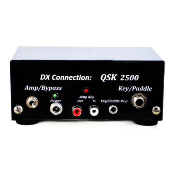
1) Description
The DX Connection QSK 2500
modifications. No amplifier T/R relay interface is required. The QSK unit will interface to amplifiers
whose key jack presents less than 200 volts positive or negative polarity to the QSK unit. The QSK 2500
adds a nominal 10 ms delay to the transceiver's normal RF delay to eliminate hot switching of the
amplifier's internal T/R changeover relay before the first dit or dah of a transmission. After the first dit
or dah, the amplifier remains keyed up for the remainder of the transmission preventing excessive T/R
relay switching. The QSK 2500
the last dit or dah of a transmission. The QSK unit incorporates hot switching T/R relay protection
caused by some transceivers removing the amplifier key signal before the RF envelop has decayed. The
QSK unit senses for RF on the amplifier RF input connector and only switches from Transmit-to-Receive
when the RF envelop is no longer present. A functional block diagram is included later in this manual.
©
The QSK 2500
Key/Paddle input jack accepts a straight key, an external keyer, a bug, a paddle (to use
the transceiver's internal keyer), computer generated CW, or anything that keys the transceiver by
grounding a circuit(s). The input device must sink about 1 ma to ground and accommodate 5 volts open
circuit. These requirements are compatible with transceiver's Key/Paddle Input jack requirements.
2) Specifications
a) RF Power: 2500 Watts CW/SSB/Data modes
b) Antenna VSWR: < 1.5:1 at 2.5KW, < 2.5:1 at 1.5KW
c) RF losses: almost lossless relays (much less loss than PIN diodes), silver plated SO-239 connectors
d) QSK internal relays: acoustically quieted and sealed for quiet operation
e) No hot switching of QSK internal relays
f)
Provides T/R relay high voltage interface for both new and older amplifiers: The QSK 2500
presents a 5VDC 1ma signal to transceiver Amp key jack. The QSK 2500
10/1/15
DX Connection
©
QSK 2500
Instruction Manual
©
allows operating a non-QSK amplifier in QSK mode with no amplifier
©
returns the amplifier to standby 2 sec to 10 sec (user settable) following
DxConnection@frontier.com
©
©
output keys (to ground)
Page 1 of 11
©
input
Advertisement

Subscribe to Our Youtube Channel
Related Manuals for DX Connection QSK 2500

Summary of Contents for DX Connection QSK 2500
- Page 1 No amplifier T/R relay interface is required. The QSK unit will interface to amplifiers © whose key jack presents less than 200 volts positive or negative polarity to the QSK unit. The QSK 2500 adds a nominal 10 ms delay to the transceiver’s normal RF delay to eliminate hot switching of the amplifier’s internal T/R changeover relay before the first dit or dah of a transmission.
- Page 2 DxConnection@frontier.com amplifier T/R relays up to +/-200VDC and 100ma. (No need for MFJ ARB-704 or Jackson Harbor Keyall Interface.) g) Amplifier TX-to-RX hot switching protection: QSK unit returns to Rx mode only after the RF envelop has decayed preventing hot switching the amplifier T/R relay. h) Amplifier RX-to-TX hot switching protection: QSK unit adds nominally 10ms (see next item) of delay to the transceiver’s internal 5 to 15ms time delay (see Table 1 below) before the start of the transceiver RF envelop output.
-
Page 3: Operation
The transceiver’s Amplifier Key jack connects to the AMP Key IN phono jack on the front of the QSK unit. The transceiver keys to ground a 5VDC 1ma signal from the QSK unit. (Contact DX Connection to use Kenwood’s +12 VDC for amplifier keying.) The QSK’s AMP Key OUT phono jack connects to the amplifier’s AMP Key IN (or ‘antenna relay’, ‘T/R relay’, or ’transmit input’) as shown in Figure 1. -
Page 4: Limited Warranty
T/R relay switching at the start of the first dit or dah of each transmission. 8) Limited Warranty DX Connection warrants to the original purchaser that this product is free from defects in material or workmanship for a 180 day period from date of original purchase. This limited warranty is for either the repair or replacement of the QSK unit only. - Page 5 DxConnection@frontier.com purchase receipt and a description of the problem to DX Connection to obtain a Return Authorization. Upon receipt of the Return Authorization, return the unit shipping prepaid to DX Connection. DX Connection will pay return shipping. 73 Contact: DX Connection email: DxConnection@frontier.com...
- Page 6 DxConnection@frontier.com Table 1: Total time for Amp T/R relay to switch (factory delay setting= 10ms) © total T/R QSK 2500 transceiver transceiver actuation comment key delay RF delay time (factory setting) Yaesu FT-1000MP MKV 5ms (min) 10ms 15ms (min) longer settings in Xcvr...
- Page 7 DxConnection@frontier.com 10/1/15 Page 7 of 11...
- Page 8 DxConnection@frontier.com amplifier transceiver © QSK 2500 (front) key/paddle key/paddle Amp Key Pwr In Amp Key Amp Key key/paddle xcvr 2 to +200 VDC to gnd or -2 to -200 VDC to gnd; 100ma (max) key, paddle, keyer DC power: 17 - 25 volts computer, bug, etc.
- Page 9 DxConnection@frontier.com 17 – 25 volts DC Key/Paddle jack power to QSK input to QSK Xcvr Key/Paddle jack Figure 3 Circuit for power switch set to ‘Bypass’ Amp relay control Amp out Xcvr relay control Amp in Xcvr Figure 4 RF circuit in ‘receive’ & ‘off’ states 10/1/15 Page 9 of 11...
- Page 10 DxConnection@frontier.com Example: QSK 2500 interface to AL-811H Amplifier Figure 5 AL-811H without QSK 2500 10/1/15 Page 10 of 11...
- Page 11 DxConnection@frontier.com AL-811H amplifier Relay transceiver © QSK 2500 (front) key/paddle key/paddle Relay Amp Key (back) (in) Pwr In key/paddle xcvr Figure 6 AL-811H Relay connections AL-811H amplifier transceiver (back) © QSK 2500 (back) RF OUT RF OUT XCVR RF IN...
Need help?
Do you have a question about the QSK 2500 and is the answer not in the manual?
Questions and answers