Table of Contents
Advertisement
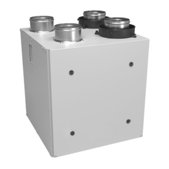
T
OP PORTS
VB0200
40E M
ODEL NO
VB0200
40H+* M
ODEL NO
50H* M
ODEL NO
*T
HESE PRODUCTS EARNED THE
GUIDELINES SET BY
STAR
REQUIREMENTS ONLY WHEN USED IN
R
®
40E, 40H+
. 44262
. 44252
. 44600
N
R
ATURAL
ESOURCES
EAD AND SAVE THESE INSTRUCTIONS
User Guide
AND
VB0201
VB0201
40H+* M
®
ENERGY STAR
C
ANADA AND THE
C
ANADA
50H
S
IDE PORTS
40E M
ODEL NO
ODEL NO
50H* M
ODEL NO
BY MEETING STRICT ENERGY EFFICIENCY
US EPA. T
HEY MEET
.
.44263
. 44253
. 44602
ENERGY
21780
. 01
REV
Advertisement
Table of Contents

Related Manuals for vanEE 40E 44263


Summary of Contents for vanEE 40E 44263
-
Page 1: User Guide
® User Guide 40E, 40H+ OP PORTS IDE PORTS VB0200 VB0201 40E M . 44262 40E M .44263 ODEL NO ODEL NO VB0201 VB0200 40H+* M . 44252 40H+* M . 44253 ODEL NO ODEL NO 50H* M . 44600 50H* M . - Page 2 Congratulations! You have made an excellent choice! The operating principle of your Heat or Energy Recovery Ventilator will give you personal comfort you have never known before. We have prepared this User Guide especially for you. Please read it carefully to ensure you obtain full benefit from your unit.
-
Page 3: Table Of Contents
Table of Contents 1. D ..............3 EFROSTING 2. C ..............4-15 ONTROLS 2.1 I ...... -
Page 4: Controls
2. Controls 2.1 Integrated control OOTING EQUENCE The unit booting sequence is similar to a personnal computer boot sequence. Each time the unit is plugged after being unplugged, or a power failure occurs, the unit will perform a 30-second booting sequence before starting to operate. During the booting sequence, the integrated control LED will light up and remain GREEN for 5 seconds, and then will turn RED. -
Page 5: Ain Control
2. Controls (cont’d) For more convenience, these units can also be controlled using a main control. Only one main control can be connected per unit. NOTES: 1. The integrated control must be turned OFF to use a main control. 2. If an optional auxiliary control is used, it’s activation will override the optional main control. - Page 6 2. Controls (cont’d) 2.2 Platinum Main Control (cont’d) OWER INDICATOR This indicator, located in upper left side of the wall control, illuminates when the control is powered on. ILTER AINTENANCE INDICATOR This indicator, located in upper right corner of the wall control, illuminates when it is time to perform the ventilation unit filter maintenance.
- Page 7 2. Controls (cont’d) 2.2 Platinum Main Control (cont’d) ETTING REFERENCES ROCEDURE NOTE: While setting Preferences, the corresponding setting value flashes (e.g.: while setting current hour, hour is flashing). Press and hold MODE/PREF key for 3 seconds to access the MODE settings menu.
- Page 8 2. Controls (cont’d) 2.2 Platinum Main Control (cont’d) OW TO SET ERIODS FOR ROGRAM The Program Mode allows the user to customize the operation of his/her ventilation unit, for week and weekend days. Each day is divided in 4 periods. The period’s starting hour and ventilation speed are factory set (see below).
- Page 9 2. Controls (cont’d) 2.2 Platinum Main Control (cont’d) ’ OW TO SET ERIODS FOR ROGRAM CONT Press SET key to confirm the choice and go to select the ventilation speed or type. Ventilation speeds and type will flash. MODE SMART PREF Use the arrow keys to select the ventilation speed or type.
- Page 10 2. Controls (cont’d) 2.3 Deco-Touch Main Control ACKLIGHT If the backlight is not illuminated, the first button pressed (no matter which button) shall turn on the backlight only, without incurring any other changes. The backlight remains illuminated for 10 seconds after the last button is pressed. VC0150 PERATING ODES...
- Page 11 2. Controls (cont’d) 2.3 Deco-Touch Main Control (cont’d) (RH) OW TO SET THE RELATIVE HUMIDITY LEVEL AND CHOOSE BETWEEN IN STANDBY RECIRCULATION IN STANDBY Setting the relative humidity level allows to select the maximum desired indoor humidity level (in percentage). This value will be used to start the dehumidistat override (air exchange in high speed). Press and hold OK for 3 sec.
- Page 12 2. Controls (cont’d) 2.3 Deco-Touch Main Control (cont’d) EHUMIDISTAT VERRIDE ELECTION In the operating modes MIN, MAX, 20 min/h and RECIRC, the user can select a dehumidistat override so that if the relative humidity (RH) in the house exceeds the RH setting previously stored, the ventilation unit will exchange in high speed until the target indoor RH setting is reached.
-
Page 13: Bronze Main Control
2. Controls (cont’d) 2.5 Simple-Touch Bronze Main Control Activate the push-button. The color of the indicator shows the unit operating mode. OLOR UGGESTED USE REEN ECIRCULATION ELECT THIS MODE WHEN YOU DEEM THE INDOOR AIR IS TOO DRY IN HEATING SEASON OR TOO HUMID DURING COOLING SEASON N THIS MODE... -
Page 14: Lighted Push Button
2. Controls (cont’d) 2.7 Optional Auxiliary Controls 2.7.1 20/40/60-minute Push-Button Timer Location: Located in the bathroom or in other locations where there is temporary humidity excess or pollutants. Purpose: To eliminate excess humidity produced by showers or other periodic activities producing pollutants. Within 2 seconds, push one time for 20 minutes, two times for 40 minutes or three times for a 60-minute activation. -
Page 15: Ehumidistat
2. Controls (cont’d) 2.7 Optional Auxiliary Controls (cont’d) 2.7.3 Dehumidistat Adjust knob to the desired maximum indoor humidity level. CAUTION Do not select a humidity level below 30%. DURING FALL, WINTER This could lead to excessive dryness in the AND SPRING, SET THE DIAL ACCORDING TO THE DESIRED MAXIMUM air causing discomfort for the occupants. -
Page 16: Aintenance
3. Maintenance WARNING Risk of electric shock. Before performing any maintenance or servicing, always disconnect the unit from its power source. Sharp edges may be present. When cleaning the unit, it is recommended to wear safety glasses and gloves. Refer to picture beside to identify the inner parts of your unit. -
Page 17: M Aintenance
3. Maintenance (cont’d) 3.1 Quarterly Maintenance (cont’d) 3. Slide out both filters (1) and recovery core (2) from the unit. 4. Clean the inside walls of the unit with a clean damp cloth, then wipe with a clean dry one. 5. -
Page 18: T Roubleshooting
4. Troubleshooting If the unit does not work properly, reset the unit by unplugging it for one minute and then replug it. If it is still not working properly, refer to table below. First make sure that the integrated control is set to OFF (no LED). ROBLEM RY THIS 1.
Need help?
Do you have a question about the 40E 44263 and is the answer not in the manual?
Questions and answers