Table of Contents

Related Manuals for HST HP101U

Summary of Contents for HST HP101U
- Page 1 © HP101U Conventional Fire Alarm Control Panel Installation And Operation Manual NOTICE All information, documentation, and specifications contained in this manual are subject to change without prior notice by the manufacturer.
-
Page 2: Fire Alarm System Limitations
Issue No. 8113 Ver1.0-2015 While a fire alarm system may lower insurance Fire Alarm System Limitations rates, it is not a substitute for fire insurance! An automatic fire alarm system–typically made up of located. smoke detectors, heat detectors, manual pull stations, Smoke particles may be blown away from detectors ... - Page 3 system, crippling its ability to report a fire. and other training exercise to make people aware of Audible warning devices such as bells may not alert fire alarm signals and instruct them on the proper people if these devices are located on the other side of reaction to alarm signals.
-
Page 4: Installation Precautions
Adherence to the following will aid in problem- Installation Precautions free installation with long-term reliability: WARNING - Several different sources of power can be Like all solid state electronic devices, this system may connected to the fire alarm control panel. Disconnect all operate erratically or can be damaged when subjected to sources of power before servicing. - Page 5 protection against such interference when operated in a of the Canadian Department of Communications. commercial environment. Operation of this equipment in a residential area is likely to cause interference, in which Le present appareil numerique n'emet pas de bruits case the user will be required to correct the interference radioelectriques depassant les limites applicables aux at his own expense.
- Page 6 Notes...
-
Page 7: Table Of Contents
Table of Contents CHAPTER 1: PRODUCT DESCRIPTION........................7 1.1 P .............................7 RODUCT EATURES 1.2 S ..............................9 PECIFICATIONS 1.3 C ..........................9 ONTROLS AND NDICATORS 1.4 C ................................13 IRCUITS 1.5 C ..............................14 OMPONENTS CHAPTER 2: INSTALLATION............................15 2.1 M ............................15 OUNTING PTIONS 2.2 B ............................15 ACKBOX OUNTING... - Page 8 APPENDIX A BATTERY CALCULATIONS......................27 APPENDIX B WIRE REQUIREMENTS........................29...
- Page 9 Main Circuit Board PANEL Terminals and Connectors Page 9 of 36...
-
Page 10: Chapter 1: Product Description
Product Description CHAPTER 1: The PANEL is a 4-zone to 16-zone FACP (Fire Alarm Control Panel), which uses conventional input devices. The panel accepts water flow devices, two-wire smoke detectors, four-wire smoke detectors, pull stations and other normally-open contact devices. Outputs include four Notification Appliance Circuits (NAC, SOUND1-4), three standard Form-A relays (alarm, trouble and supervisory) and an EIA-485 port to interface with remote annunciators and optional remote relay modules. - Page 11 Page 11 of 36...
- Page 12 The functions of terminal Page 12 of 36...
- Page 13 Page 13 of 36...
-
Page 14: Specifications
1.2 Specifications AC Power 90-270 VAC, 50 Hz, 2.3 amps Wire size: minimum #14 AWG (2.0 mm ) with 600V insulation Battery (lead acid only) Maximum Charging Circuit: Normal Flat Charge—27.6V @ 0.8 amp Maximum Charger Capacity: 18 Amp Hour batter Sound Output Device Circuits General Alarm Zones 1 through 16 Operation: All zones Class B... - Page 15 NAC Fault - yellow LED Manual - red LED Automatic - red LED Sound1 to 4 - red LED or yellow LED Zone Fire Alarm - red LED Zone Fault Alarm - yellow LED Ground Fault - yellow LED ...
- Page 16 Page 16 of 36...
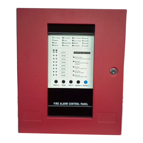
- Page 17 FIGURE 1.3.2: PANEL-8 LEDs and Keypad Page 17 of 36...
- Page 18 FIGURE 1.3.3: PANEL-16 LEDs and Keypad Page 18 of 36...
-
Page 19: Circuits
Local Sounder A piezo sounder provides separate and distinct sounds for alarm, trouble and supervisory conditions: Alarm - pulse ½ second On and ½ second OFF Fault - pulse 1½ second On and 4 second OFF Supervisory - pulse ½ second On and ½ second OFF ... -
Page 20: Components
1.5 Components Main Circuit Board The main circuit board contains the system's CPU, power supply, other primary components and wiring interface connectors. Optional modules plug in and are mounted to the main circuit board. The main circuit board is delivered pre-mounted in the cabinet. Cabinet The cabinet is red and the backbox measures 14.57"... -
Page 21: Chapter 2: Installation
Installation CHAPTER 2 2.1 Mounting Options The cabinet may be either semi-flush or surface mounted. The door is attached to the cabinet by two hinges. The cabinet mounts using two key slots and one additional 0.250" (6.35 mm) diameter holes located in the backbox. The key slots are located at the top of the backbox and the one securing holes at the bottom. -
Page 22: Operating Power
Draw wires through the respective knockout locations. Cabinet Dimensions and Knockout Locations FIGURE 2-2: 2.3 Operating Power WARNING: Several different sources of power can be connected to this panel. Disconnect all sources of power before servicing. The panel and associated equipment may be damaged by removing and/or inserting cards, modules or interconnecting cables while this unit is energized. -
Page 23: Power
Calculations” on page 27 for calculation of the correct battery rating. WARNING: Battery contains sulfuric acid which can cause severe burns to the skin and eyes and can destroy fabrics. If contact is made with sulfuric acid, immediately flush the skin or eyes with water for 15 minutes and seek immediate medical attention. - Page 24 Page 24 of 36...
-
Page 25: Input Zones Circuits
2.4 Input Zones Circuits The control panel has 4-16 zone input circuits. The maximum loop resistance limit for each input circuit is 100 ohms. All field wiring of each zone is supervised for opens and ground faults. Both conditions are visually and audibly annunciated. -
Page 26: Dc Power Output Connections
One alarm option J1 jump on the PCB board, you can select Normal Close(NC) or Normal Open(NO) alarm. 2.6 DC Power Output Connections Nonresettable Power (1000 mA) 24 VDC 4-Wire Smoke Detector Power (1000 mA) 24VDC filtered, filtered, nonresettable power can be obtained resettable power for 4-wire smoke detectors can be obtained from Terminals 1(+) and 2(-). -
Page 27: Relays Output
2.9 Relays Output The control panel provides three relays rated for 2.0 amps @ 30 VDC (resistive) and 2.0 amps @ 30 VAC(resistive). Relay connections may be power-limited or nonpower-limited, provided that a minimum of 0.25" is maintained between conductors of power-limited and nonpower-limited circuits. The ALARM RELAY is open in normal , it will be close in a any alarm. -
Page 28: Chapter 3: Programming Instructions
Programming Instructions CHAPTER 3: This chapter describes programming the PANEL from the onboard keypad. Programming can be performed only by a factory authorized representative. Control panel programming is possible at any time except when an alarm or zone fault condition is present or during a fire test. All programming selections are stored in nonvolatile Electrically-Erasable Programmable Read-Only Memory (EEPROM). -
Page 29: Zone Disable
3.5 Zone Disable 1. Press and held Mode key for more than three seconds until the Activate LED blinks. 2. Press “Up” and “Down” arrow key to select Zone Disable LED blinks. 3. Press “Enter (Mode)” key to enter Zone Disable menu. 3. -
Page 30: Chapter 4: Operating Instructions
Operating Instructions CHAPTER 4 The PANEL has two modes of operation which are Normal, Program. Upon initial power-up, the system will be in Normal Mode. This section discusses operation of the control panel in the Normal Mode. 4.1 Switch Functions in Normal Mode Silence A Silence key is located on the PANEL keypad (illustrated in Figure 4-1). -
Page 31: Status Leds
The System Reset key resets the system and any detectors. A Reset key is located on the PANEL keypad (illustrated in Figure 4-1). If the System Reset keys are pressed, the control panel will: ✓ Clear the status LEDs ✓ Turn off the Notification Appliance Circuits ✓... -
Page 32: Operation
flash LED indicates the program features. Manual LED A red LED that turn on to indicate that the panel is running in manual mode. In manual mode, All Notification Appliance Circuits (Sound1-Sound 4 Output) have been disabled, but Sound1-Sound 4 Output can be activated by manual. -
Page 33: Fire Alarm Response
4.3.1 Fire Alarm Response The control panel will, upon detection of an alarm condition, cause the following: Turn on the system Alarm LED Blink the Zone Alarm Red LED (½ second On, ½ second Off) Turn the Notification Appliance Circuits on ... - Page 34 Appendix A Battery Calculations Use the Total Standby and Alarm Load Currents calculated in Table A-2 and Table A-3 for the following battery calculation. TABLE A-1: Battery Calculation Standby Load Required Standby Time in Hours Current (amps) (24 or 60 Hours) Alarm Load Required Alarm Time in Hours Current (amps)
- Page 35 A.1 Main Power Supply The PANEL provides filtered power for operating the fire alarm control panel, operating external devices and operating the standby battery. The power for operating external devices is limited. Use Table A-2 (standby or non-alarm) and Table A-3 (alarm) to determine if external loading is within the capabilities of the power supply. TABLE A-2: Filtered Load in Standby @24 VDC.
- Page 36 Appendix B Wire Requirements Connecting external system accessories to the PANEL main circuits must be carefully considered to ensure proper operation. It is important to use the correct type of wire, wire gauge and wire run length per each PANEL circuit. Reference the chart below to specify wire requirements and limitations for each PANEL.
Need help?
Do you have a question about the HP101U and is the answer not in the manual?
Questions and answers