U-Line 3018WC User Manual
Modular 3000 series 18" wine captain
Hide thumbs
Also See for 3018WC:
- Operating instructions manual (13 pages) ,
- User manual (77 pages) ,
- User manual & service manual (67 pages)

Related Manuals for U-Line 3018WC


Summary of Contents for U-Line 3018WC
- Page 1 USER GUIDE SAFETY • INSTALLATION & INTEGRATION • OPERATING INSTRUCTIONS • MAINTENANCE • SERVICE RIGHT PRODUCT. RIGHT PLACE. RIGHT TEMPERATURE. SINCE 1962. Modular 3000 Series 3018WC 18" Wine Captain Model ® • •...
-
Page 2: Table Of Contents
Integrated Panel Dimensions Integrated Grille / Plinth Dimensions Integrated Panel Installation Grille / Plinth Installation Door Swing Door Stop Door Adjust Operating Instructions First Use Control Operation Sabbath Mode Airflow and Product Loading U-Line Wine Guide Recommended Wine Storage Maintenance... - Page 3 1. U-Line Customer Care must be contacted immediately at +1.800.779.2547. 2. Service or repairs performed on the unit without prior written approval from U-Line is not permitted. If the unit has been altered or repaired in the field without prior written approval from U-Line, claims will not be eligible.
-
Page 4: Safety And Warning
USER GUIDE u-line.com SAFETY • INSTALLATION & INTEGRATION • OPERATING INSTRUCTIONS • MAINTENANCE • SERVICE Safety and Warning DANGER NOTICE This unit contains R600a (Isobutane) which is a Please read all instructions before installing, flammable hydrocarbon. It is safe for regular operating, or servicing the appliance. - Page 5 USER GUIDE u-line.com SAFETY • INSTALLATION & INTEGRATION • OPERATING INSTRUCTIONS • MAINTENANCE • SERVICE Disposal and Recycling DANGER RISK OF CHILD ENTRAPMENT. Before you throw away your old refrigerator or freezer, take off the doors and leave shelves in place so children may not easily climb inside.
-
Page 6: Environmental Requirements
USER GUIDE u-line.com SAFETY • INSTALLATION & INTEGRATION • OPERATING INSTRUCTIONS • MAINTENANCE • SERVICE Environmental Requirements This model is intended for indoor/interior applications only and is not to be used in installations that are open/ exposed to natural elements. - Page 7 USER GUIDE u-line.com SAFETY • INSTALLATION & INTEGRATION • OPERATING INSTRUCTIONS • MAINTENANCE • SERVICE Electrical WARNING SHOCK HAZARD — Electrical Grounding Required. Never attempt to repair or perform maintenance on the unit until the electricity has been disconnected. Never remove the round grounding prong from the plug and never use a two-prong grounding adapter.
-
Page 8: Cutout Dimensions
SAFETY • INSTALLATION & INTEGRATION • OPERATING INSTRUCTIONS • MAINTENANCE • SERVICE Cutout Dimensions CUTOUT DIMENSIONS PREPARE SITE Your U-Line product has been designed exclusively for a built-in installation. When built-in, your unit does not Preferred location require additional air space for top, sides, or rear. -
Page 9: Product Dimensions
USER GUIDE u-line.com SAFETY • INSTALLATION & INTEGRATION • OPERATING INSTRUCTIONS • MAINTENANCE • SERVICE Product Dimensions 24" (610 mm) (Includes 3/4" [20 mm] Integrated Panel) 33-11/16" to 34-11/16" (856 mm to 881 mm) 3-5/8" to 4-5/8" 17-3/4" (92 mm to 118 mm) -
Page 10: Side By Side Installation
USER GUIDE u-line.com SAFETY • INSTALLATION & INTEGRATION • OPERATING INSTRUCTIONS • MAINTENANCE • SERVICE Side-by-Side Installation Hinge-by-Hinge Installation (Mullion) When installing two units hinge-by-hinge, 13/16" (22 mm) OTHER SITE REQUIREMENTS is required for integrated models. Additional space may be Side-by-Side Installation needed for any knobs, pulls or handles installed. -
Page 11: Anti-Tip Bracket
USER GUIDE u-line.com SAFETY • INSTALLATION & INTEGRATION • OPERATING INSTRUCTIONS • MAINTENANCE • SERVICE Anti-Tip Bracket 5. Using a 3/32" drill bit, drill 3 pilot holes 5/8" (16 mm) deep into bottom of countertop. Use the anti-tip bracket as a template. - Page 12 USER GUIDE u-line.com SAFETY • INSTALLATION & INTEGRATION • OPERATING INSTRUCTIONS • MAINTENANCE • SERVICE 5. Using a 3/32" drill bit, drill 3 pilot holes 5/8" (16 mm) deep into cabinetry frame using the anti-tip bracket as a template. 6. Install the 3 remaining #8x5/8" screws into the plate using a #2 Phillips head screwdriver.
-
Page 13: General Installation
USER GUIDE u-line.com SAFETY • INSTALLATION & INTEGRATION • OPERATING INSTRUCTIONS • MAINTENANCE • SERVICE General Installation INSTALLATION 1. Plug in the power/electrical cord. 1. Use a level to confirm the unit is level. Level 2. Gently push the unit into position. Be careful not to should be placed along entangle the cord. -
Page 14: Integrated Panel Dimensions
USER GUIDE u-line.com SAFETY • INSTALLATION & INTEGRATION • OPERATING INSTRUCTIONS • MAINTENANCE • SERVICE Integrated Panel Dimensions Integrated Frame Dimensions INTEGRATED FRAME BACK SURFACE MUST HAVE AMPLE FLAT SURFACE TO MOUNT OVERLAY FRAME FLAT AND WITHOUT 3/4" INTERFERENCE (20 mm) NOTICE 17-1/2"... - Page 15 3-1/2" (89 mm) NOTE: Many cabinet manufacturers provide a ready solution for a handleless, integrated design that can be easily applied to your U-Line 3000 Series model. Consult your cabinet manufacturer for applicable design and installation details. The cabinet manufacturer’s solution to...
- Page 16 USER GUIDE u-line.com SAFETY • INSTALLATION & INTEGRATION • OPERATING INSTRUCTIONS • MAINTENANCE • SERVICE Handleless Integrated Frame Dimensions 1/8" (3 mm) Top Design 1/4" (6 mm) 7/8" (22 mm) Ref. R 5/8" 2-3/8" (R 16 mm) (60 mm) 17-1/2"...
- Page 17 USER GUIDE u-line.com SAFETY • INSTALLATION & INTEGRATION • OPERATING INSTRUCTIONS • MAINTENANCE • SERVICE EXTENDED INTEGRATED FRAME NOTICE Due to differences in surrounding cabinetry the panel may not perfectly align with door. The procedure below is designed to provide a finished panel that seamlessly integrates with surrounding cabinetry.
- Page 18 USER GUIDE u-line.com SAFETY • INSTALLATION & INTEGRATION • OPERATING INSTRUCTIONS • MAINTENANCE • SERVICE Integrated Panel/Integrated Frame Integrated Panel U-Line U-Line Cabinet Unit Unit 3-5/16" (89 mm) 3-5/16" (89 mm) > 3-5/16" 4-5/16" (114 mm) 4-5/16" (114 mm) (> 89 mm)
- Page 19 USER GUIDE u-line.com SAFETY • INSTALLATION & INTEGRATION • OPERATING INSTRUCTIONS • MAINTENANCE • SERVICE Extended Integrated Frame Dimensions BACK SURFACE MUST HAVE AMPLE FLAT SURFACE 3/4" TO MOUNT INTEGRATED FRAME FLAT AND WITHOUT INTERFERENCE (20 mm) 17-1/2" (445 mm) 2-3/4"...
-
Page 20: Integrated Grille / Plinth Dimensions
3. Apply double sided tape to the backside of the integrated grill (plinth strip/base fascia). Use the diagram below for reference. U-Line recommends ™ ™ tape, a high strength bonding tape. -
Page 21: Integrated Panel Installation
NOTICE clamps. A robust tape may also be If the door/drawer houses the display, make used. U-Line certain the display cable remains securely recommends the seated in the inner door channel, see below. Door/Drawer use of bar clamps... - Page 22 USER GUIDE u-line.com SAFETY • INSTALLATION & INTEGRATION • OPERATING INSTRUCTIONS • MAINTENANCE • SERVICE 9. Using a Phillips screwdriver, place one screw into each of the 6 pilot holes and screw down. Do not overtighten screws. 10.Be sure the screws force their way past the opening on the gasket channel and sit flush against the bottom of the channel.
-
Page 23: Grille / Plinth Installation
USER GUIDE u-line.com SAFETY • INSTALLATION & INTEGRATION • OPERATING INSTRUCTIONS • MAINTENANCE • SERVICE Grille - Plinth Installation Installing the grille (plinth strip/base fascia) REMOVING AND INSTALLING GRILLE 1. Align slots in grille (plinth strip/base fascia) rail with (PLINTH STRIP/BASE FASCIA) -
Page 24: Door Swing
USER GUIDE u-line.com SAFETY • INSTALLATION & INTEGRATION • OPERATING INSTRUCTIONS • MAINTENANCE • SERVICE Door Swing Wall For Integrated models that are installed adjacent to a wall, 1/4" (6 mm) 1/4" (6 mm) clearance is recommended from wall on hinge side to allow the door to open 90°. -
Page 25: Door Stop
3. Once cover is removed, slide hinge pin into hole as shown. Pin should slide into place, stopping the door at Your U-Line unit was shipped to you with the optional 90° 90°; if the pin does not go into the hole shown, hold pin. -
Page 26: Door Adjust
USER GUIDE u-line.com SAFETY • INSTALLATION & INTEGRATION • OPERATING INSTRUCTIONS • MAINTENANCE • SERVICE Door Adjustments Alignment and Adjustment Procedure 1. Remove integrated panel, if installed. DOOR ALIGNMENT AND ADJUSTMENT Align and adjust the door if it is not level or is not sealing 2. -
Page 27: First Use
USER GUIDE u-line.com SAFETY • INSTALLATION & INTEGRATION • OPERATING INSTRUCTIONS • MAINTENANCE • SERVICE First Use All U-Line controls are preset at the factory. Initial startup requires no adjustments. NOTICE U-Line recommends allowing the unit to run overnight before loading with product. -
Page 28: Control Operation
USER GUIDE u-line.com SAFETY • INSTALLATION & INTEGRATION • OPERATING INSTRUCTIONS • MAINTENANCE • SERVICE Control Operation Zone Toggle Select White Wine 5O°F Can be displayed in Celsius Power Down U-Select Lighting CONTROL FUNCTION GUIDE FUNCTION COMMAND DISPLAY/OPTIONS Press and hold Display will count down from 5 to off. - Page 29 USER GUIDE u-line.com SAFETY • INSTALLATION & INTEGRATION • OPERATING INSTRUCTIONS • MAINTENANCE • SERVICE ® U-SELECT CONTROL Quick Chill Digital Display CAUTION The 3000 Series units are controlled by a feature rich, advanced OLED display control unit. The control panel...
- Page 30 SAFETY • INSTALLATION & INTEGRATION • OPERATING INSTRUCTIONS • MAINTENANCE • SERVICE INTERIOR LIGHTING Description Solution (L) (R) Zone T Left or right zone Contact Customer Your U-Line 3000 Series unit uses a state of the art LED Short thermistor circuit Care. lighting system. shorted. Amb Thrm...
- Page 31 LANGUAGES ENGLISH 2. Press to scroll through available information. Down The U-Line 3000 Series of models supports a number of 3. To return to the Customer Menu, press and select display languages including English, Spanish, French, “Return to Menu”. Italian and German.
- Page 32 USER GUIDE u-line.com SAFETY • INSTALLATION & INTEGRATION • OPERATING INSTRUCTIONS • MAINTENANCE • SERVICE Sound Level 3. Press to select between °F (Fahrenheit) or °C (Celsius). Select RETURN TO MENU 4. Press to confirm your choice. SOUND LEVEL HIGH...
- Page 33 To access the Help Menu, select “Help” from the Customer Menu. Press to scroll through available information. The Help screen displays the following: • Model. • U-Line contact information. • Software version. • Serial Number. To exit the Help Menu, press to select “Return to Menu”...
-
Page 34: Sabbath Mode
USER GUIDE u-line.com SAFETY • INSTALLATION & INTEGRATION • OPERATING INSTRUCTIONS • MAINTENANCE • SERVICE 7. Press to change “Off” to “On”. Sabbath Mode 8. Press to confirm your selection. The Display will fade out as the unit enters Sabbath Mode. -
Page 35: Airflow And Product Loading
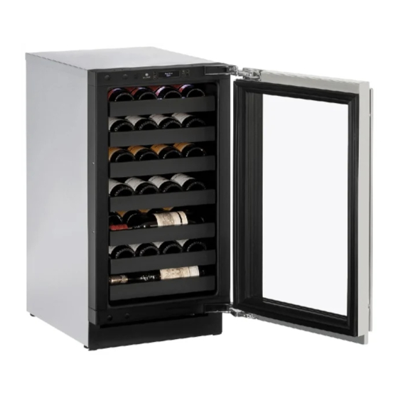
Do not install the unit behind a door. When properly loaded, your U-Line unit will store up to 31 (750 ml) bottles of wine. Door Removed For Illustration Purposes Internal Air Flow And Unit Ventilation Diagram... -
Page 36: U-Line Wine Guide
YOUNG wine OLD wine LIGHT-BODIED wine FULL-BODIED wine Any step back in quality will be noticed. If a fine wine is tasted prior to a lesser wine, many of the fine wine’s subtle qualities may be missed. U-Line Wine Guide 1... - Page 37 Great Bordeaux’s may have as much as a 10-year plateau before fading. Myth 4: Wine color does not change with aging. Truth: As red wines age they get lighter in color while whites get darker. U-Line Wine Guide 2...
- Page 38 Wines can become flat or tired when voids and vacuums are created inside the wine bottle. In order to create voids and vacuums within a liquid, aggressive motion or shaking of the wine bottle would have to occur. U-Line Wine Guide 3...
- Page 39 Approximately 45°F (7°C) Sparkling ® Wine Captain Models - A Touch of Elegance In 1985 U-Line was the first North American appliance manufacturer to develop a residential wine storage unit, ® ® the Wine Captain . Each U-Line Wine Captain...
-
Page 40: Recommended Wine Storage
Specially designed horizontal wine racks properly position the bottles so the wine remains in contact with the cork, which ensures the cork does not become dry. U-Line recommends arranging wine bottles as shown in the illustrations below. Racks 1 through 5: Larger diameter bottles may be stored on the shaded racks, illustrated below. -
Page 41: Maintenance
® monthly. For best results use Claire Stainless Steel Polish and Cleaner, which can be purchased from U-Line Rinse the interior using a soft sponge and clean water. Corporation (Part Number 173348). Comparable products are acceptable. Frequent cleaning will remove surface contamination that could lead to rust. - Page 42 USER GUIDE u-line.com SAFETY • INSTALLATION & INTEGRATION • OPERATING INSTRUCTIONS • • SERVICE MAINTENANCE NOTICE The drain pan was not designed to capture the water created when manually defrosting. To prevent water from overflowing the drain pan and possibly damaging water sensitive flooring, the unit must be removed from cabinetry.
-
Page 43: Cleaning Condenser
USER GUIDE u-line.com SAFETY • INSTALLATION & INTEGRATION • OPERATING INSTRUCTIONS • MAINTENANCE • SERVICE Cleaning Condenser INTERVAL - EVERY SIX MONTHS To maintain operational efficiency, keep the front grille (plinth strip/base fascia) free of dust and lint, and clean the condenser when necessary. -
Page 44: Wine Rack Installation
USER GUIDE u-line.com SAFETY • INSTALLATION & INTEGRATION • OPERATING INSTRUCTIONS • MAINTENANCE • SERVICE Wine Rack Installation To insert wine racks in the cabinet: 1. Align the left and right rack channels with the tracks in To remove wine racks for cleaning: the cabinet. -
Page 45: Extended Non-Use
If the unit will be exposed to temperatures of 40°F (5°C) or less, the steps above must be followed. For questions regarding winterization, please call U-Line at +1.800.779.2547. CAUTION Damage caused by freezing temperatures is not covered by the warranty. -
Page 46: Accessories
USER GUIDE u-line.com SAFETY • INSTALLATION & INTEGRATION • OPERATING INSTRUCTIONS • MAINTENANCE • SERVICE Accessories 23054-01 Accessories - Stainless Steel PRO Style Door Handle, 1-1/4" in diameter US$49.00 Accessories 1... -
Page 47: Troubleshooting
• Compressor: The compressor makes a hum or pulsing sound that may be heard when it operates. BEFORE CALLING FOR SERVICE If you think your U-Line product is malfunctioning, read • Evaporator: Refrigerant flowing through an evaporator the CONTROL OPERATION section to clearly understand may sound like boiling liquid. - Page 48 12H+ temperature +10° and sealing. Contact properly. For other error codes contact over set point for Customer Care if U-Line Customer Service. over 12 hours. persistent. Product Is Because product in contact with the rear wall (L) (R) Temp Lo...
- Page 49 USER GUIDE u-line.com SAFETY • INSTALLATION & INTEGRATION • OPERATING INSTRUCTIONS • MAINTENANCE • SERVICE 6. After 24 hours, check the temperature of the water. If required, adjust the temperature control in a small increment (see CONTROL OPERATION). Causes which affect the internal temperatures of the cabinet include: •...
-
Page 50: Warranty
God, such as fire, floods, wind, and U-Line product to be free from defects in materials and lightning; damages incurred or resulting from shipping, workmanship for a period of five years from the date of improper installation, unauthorized modification, or purchase. - Page 51 7. If a product defect is discovered during the applicable warranty period, you must promptly notify either U-Line at 8900 N. 55th Street, Milwaukee, Wisconsin 53223 USA or at +1.800.779.2547 or the dealer from whom you purchased the product. In no event shall such notification be received later than 30 days after the expiration of the applicable warranty period.
Need help?
Do you have a question about the 3018WC and is the answer not in the manual?
Questions and answers