Table of Contents
Advertisement
Quick Links
Advertisement
Table of Contents

Related Manuals for Harris NEXIO AMP NX3801HDX


Summary of Contents for Harris NEXIO AMP NX3801HDX
- Page 1 NEXIO AMP Hardware Installation and User Guide...
- Page 3 NEXIO AMP (NX3801HDX) Shared Storage Server Hardware Installation and User Guide 175-100244-00 REV A April 2011...
- Page 4 Harris Corporation reserves the right to revise this documentation and to make changes in content Mason, OH USA 45040 from time to time without obligation on the part of Harris Corporation to provide notification of such revision or change. Media & Workflow 9800 South Meridian Blvd.
-
Page 5: Table Of Contents
RAID Redundancy ..................26 Timecode Connection Options ..............26 Remote GPI Control ..................27 Remote Serial Interface ................27 Controls ....................27 Physical .....................27 Power Supply ....................28 Supported Television Formats ..............28 Chapter 2 Hardware Installation ................29 Rear Panel Port Connectors ...............31 ©2011 Harris Corporation. All rights reserved. - Page 6 FTP Folders ....................85 LLM Parameters ..................86 Error Logging ....................87 LLM ......................89 MPEG ......................91 FTP ......................93 Startup ......................95 CV/Logo ....................97 Other ......................99 LLM 1 ......................101 Chapter 5 Monitoring Server Status ..............103 LED Indicators ....................103 NEXIO Monitor ....................104 ©2011 Harris Corporation. All rights reserved.
- Page 7 Testing the LED Lights ................106 Selecting Monitored Diagnostics ............. 106 Checking Status ..................107 LCD Keypad Buttons ................... 109 Chapter 6 Connectors, Jumper Settings, and Circuits ......111 Chapter 7 Troubleshooting ................... 123 ©2011 Harris Corporation. All rights reserved.
- Page 8 Contents ©2011 Harris Corporation. All rights reserved.
- Page 9 To create or modify a configuration preset ............64 To restore the factory default settings ..............65 To specify a default preset ................66 To select a configuration and include or exclude options ........70 To specify video options ...................71 ©2011 Harris Corporation. All rights reserved.
- Page 10 Chapter 6 Connectors, Jumper Settings, and Circuits ......111 To assemble a MDR connector ..............117 Chapter 7 Troubleshooting ................... 123 To remove the failed drive ................123 To manually start the Rebuild ................ 124 ©2011 Harris Corporation. All rights reserved.
-
Page 11: About This Guide
About This Guide provides an overview of this guide, describes guide conventions, and tells you where to look for specific information. This section also gives you important information on unpacking and shipping your Harris product. This guide introduces and describes procedures for installing and using NEXIO AMP™. - Page 12 Information about connectors, jumper Chapter 6, Connectors, settings, and circuits for NEXIO AMP Jumper Settings, and Circuits on page 111 Troubleshooting information on how to Chapter 7, remove, replace, and rebuild a boot drive Troubleshooting page 123 ©2011 Harris Corporation. All rights reserved.
- Page 13 Danger text Indicates information that conditions or practices that can result in personal injury or loss of life. Warning text Indicates information that if not followed could prevent system operation or cause it damage. ©2011 Harris Corporation. All rights reserved.
-
Page 14: Related Documentation
Manuals, User Guides and other documents can be viewed or downloaded from the Harris website at http://ecustomer.broadcast.harris.com. In the Customer Login area, enter your User ID and Password, and click OK. Click New User to register with Harris. The Welcome page appears. Click Review Documentation. -
Page 15: Purchasing Documents
Confirm that you have received all items listed on the packing list. Contact your Harris NEXIO dealer if any item on the packing list is missing. Contact the carrier if any item is damaged. Remove all packaging material from the product and its associated components before you install the unit. -
Page 16: Technical Support
The corners of the product must be protected. If the product is still within the warranty period, Harris Corporation will return it to you by prepaid ground shipping after servicing. Technical Support Technical support is available 24 hours a day, 7 days a week. You can contact technical support by phone or e-mail. - Page 17 Asia, Pacific Rim 24 hours a day, 7 days a week Regular Business Hours (9am to 5pm HKT Monday to Friday) Call: +852-2776-0628 After-Hour Hotline: 1-888-534-8246 Fax: +852-2776-0227 Email: BCDService@harris.com ©2011 Harris Corporation. All rights reserved.
- Page 18 About This Guide ©2011 Harris Corporation. All rights reserved.
- Page 19 NEXIO AMP Configurations on page 10 NEXIO AMP Upgrades and Options on page 11 Optional Software Applications on page 12 Key Features on page 13 Specifications on page 15 ©2011 Harris Corporation. All rights reserved.
- Page 20 1-1. The Software License Card provided with your server shows which configuration you have purchased. If you want to upgrade to a different configuration, contact Harris BCD Support for an additional license. For details on licensing your software, see Registering Your Software on page 51 or the Software License Card provided with your server.
- Page 21 4 channels of AVC-Intra play out (50 and 100 Mbps) or 2 channels of AVC-Intra encoding. To determine if your system meets the requirements needed for NEXIO AMP NXCP Codec Processor Upgrade, contact Harris Customer Support. NEXIO Intrinsic Mirroring — Intrinsic Mirroring is an additional cost option ...
-
Page 22: Chapter 1 Introduction
To purchase optional software applications, contact your Harris Sales Representative. For details on Harris NEXIO AMP Media Applications, please visit www.broadcast.harris.com/nexioamp/, or contact your Harris Sales Representative. ©2011 Harris Corporation. All rights reserved. -
Page 23: Key Features
150 Mbps MPEG-2 MP@HL Long GOP 4:2:0 profile and 4:2:2 profile up to 80 Mbps XDCAM HD at 35 Mbps (not available in 720p) DVCPRO HD at 100 Mbps ©2011 Harris Corporation. All rights reserved. - Page 24 Includes FTP Server to move media from server-to-server and between attached general purpose drives MXF OP-1a QuickTime Native LXF MPEG2 PS/TS Ingest Pinnacle private audio stream (mixed services with MPEG audio) ©2011 Harris Corporation. All rights reserved.
-
Page 25: System
The following table describes NEXIO AMP video specifications. All SD and HD Input/Output Configurations require that you have registered your software. To register your software, see the Software License Card provided with your system. ©2011 Harris Corporation. All rights reserved. - Page 26 HD Aspect 16:9 Ratio Aspect Ratio Up/down/cross conversion support (SD only) Conversion EIA-608 <> 708 & WST <> OP-47 caption conversion AFD aspect ratio conversion Port based aspect ratio conversion User-based aspect ratio conversion ©2011 Harris Corporation. All rights reserved.
-
Page 27: Audio
23 Table 1-9 4 Channel Mode — High Definition Video Compression Specifications (for servers connected via Media Host architecture) page 24 Table 1-10 High Definition Video Compression Specification for AVC-Intra on page 25 ©2011 Harris Corporation. All rights reserved. - Page 28 525 @ 29.97fps Mbps 625 @ 25fps DVCPRO — 25 and 50 525 @ 29.97fps Mbps 625 @ 25fps DVCAM* — 25 Mbps 625 @ 25fps *DVCPRO25 is the same as DVCAM in 525 @ 29.97fps. ©2011 Harris Corporation. All rights reserved.
- Page 29 720p @ 50fps XDCAM HD — 35 Mbps 1080i @ 29.97fps (not available in 720p) 1080i @ 25fps XDCAM HD422 — 50 1080i @ 29.97fps Mbps 720p @ 59.94fps 1080i @ 25fps 720p @ 50fps ©2011 Harris Corporation. All rights reserved.
- Page 30 HD video compression coding and decoding for the following when connected via Media Host architecture: 2 Channel (1 bi-directional + 1 play only) 2 Channel (2 bi-directional + 0 play only) ©2011 Harris Corporation. All rights reserved.
- Page 31 720p @ 50fps DVCPRO HD — 100 1080i @ 29.97fps Mbps 720p @ 59.94fps 1080i @ 25fps 720p @ 50fps XDCAM HD — 35 Mbps 1080i @ 29.97fps (not available in 720p) 1080i @ 25fps ©2011 Harris Corporation. All rights reserved.
- Page 32 1080i @ 25fps 720p @ 50fps H.264 (decode only) 1080i @ 29.97fps 720p @ 59.94fps 1080i @ 25fps 720p @ 50fps DNxHD 1080i @ 29.97fps 720p @ 59.94fps 1080i @ 25fps 720p @ 50fps ©2011 Harris Corporation. All rights reserved.
- Page 33 720p @ 50fps XDCAM EX — 35 Mbps 1080i @ 29.97fps 720p @ 59.94fps 1080i @ 25fps 720p @ 50fps H.264 (decode only) 1080i @ 29.97fps 720p @ 59.94fps 1080i @ 25fps 720p @ 50fps ©2011 Harris Corporation. All rights reserved.
- Page 34 1080i @ 29.97fps 25, 35, 50, 70, and 80 720p @ 59.94fps Mbps 1080i @ 25fps 720p @ 50fps XDCAM HD — 35 Mbps 1080i @ 29.97fps (not available in 720p) 1080i @ 25fps ©2011 Harris Corporation. All rights reserved.
- Page 35 AVC-Intra: 1080i @ 29.97fps 720p @ 59.94fps 0 ingest + 2 play only 1080i @ 25fps 0 ingest + 3 play only 720p @ 50fps 0 ingest + 4 play only ©2011 Harris Corporation. All rights reserved.
-
Page 36: Storage
Chapter 1 Introduction Storage NEXIO AMP can be connected to storage via direct Fibre Channel, NX1000MIOH, NX1010MIOH, or NX1011MIOH. For more information, contact your Harris Sales Representative. RAID The following table describes NEXIO AMP RAID redundancy specifications. Redundancy Table 1-11 RAID Redundancy Specifications Controller RAIDsoft™... -
Page 37: Remote Gpi Control
The following table describes NEXIO AMP size specifications. Table 1-14 Size Specifications Height 5.25 in. (13.4 cm); 3RU Width 19 in. (48.3 cm) Length 26 in. (71.4 cm) from the rack ears to the rear panel Weight 47 lbs. (21.3 kg) ©2011 Harris Corporation. All rights reserved. -
Page 38: Power Supply
Television 525 @ 29.97fps Formats 625 @ 25fps 720p @ 59.94fps 720p @ 50fps 1080i @ 29.97fps 1080i @ 25fps 1080p @ 29.97fps 1080p @ 25fps ©2011 Harris Corporation. All rights reserved. -
Page 39: Chapter 2 Hardware Installation
The surfaces must be clear of obstructions to provide proper air circulation and cooling. External device connections — Video monitors and all connections to external devices should be available and in working order. ©2011 Harris Corporation. All rights reserved. -
Page 40: To Rack Mount Nexio Amp
Press the release button on the outside of the rail and slide the NEXIO AMP all the way into the rack. rear rack posts front rack posts slide extension release button release latch slide Figure 2-1 Rack Mounting ©2011 Harris Corporation. All rights reserved. -
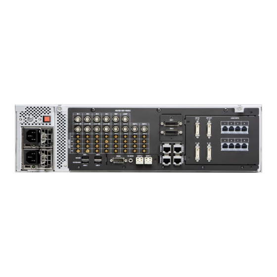
Page 41: Rear Panel Port Connectors
The NEXIO AMP rear panel is shown in Figure 2-2. Port Connectors Figure 2-2 NEXIO AMP Rear Panel The function of each connector is shown in Table 2-1. For additional information, Rear Panel Port Descriptions on page 34. ©2011 Harris Corporation. All rights reserved. - Page 42 AES/EBU audio and Dolby E for input 3. Four HD-BNC connectors for AES/EBU audio input. Connect to these ports 1/2, 3/4, 5/6, 7/8 when using AES/EBU audio and Dolby E for input 4. ©2011 Harris Corporation. All rights reserved.
- Page 43 Two 26-pin MDR connectors for GPI input. GPI OUT 1-8, 9-16 Two 26-pin MDR connectors for GPI output. COM Ports COM PORTS Eight RJ-12, RS-422 ports for serial control. 1, 2, 3, 4, 5, 6, 7, 8 ©2011 Harris Corporation. All rights reserved.
-
Page 44: Rear Panel Port Descriptions
Look at the status LED on the front of each power supply. The LED on the failed power supply will not be illuminated. Handle Status Release Figure 2-3 Power Supply Module To remove a power supply, push the release tab to the left. ©2011 Harris Corporation. All rights reserved. -
Page 45: To Insert A New Power Supply
AMP to your house time clock. When recording from a satellite feed, apply frame synchronization hardware between the receiver and the video input channel. The synchronization hardware and the NEXIO AMP mainframe must be connected to the house reference. ©2011 Harris Corporation. All rights reserved. - Page 46 USB ports can be used to connect devices to the server. The following USB devices can be used as sources and destinations when moving content in and out of the server: USB CD-ROM/R/RW drives (source only) USB DVD-ROM/RW/RAM drives (source only) ©2011 Harris Corporation. All rights reserved.
-
Page 47: Fibre Channel
DVI1 is the primary DVI port. DVI2 is optional. If the DVI2 connection is used, it supports spanning of the desktop or a second simultaneous instance of the desktop. ©2011 Harris Corporation. All rights reserved. - Page 48 Only available when a Media Host architecture is used. Gigabit Ethernet is required. No Teaming allowed. No FTP allowed on chassis when Media Host architecture is used. ©2011 Harris Corporation. All rights reserved.
- Page 49 Protocol can be used via any Ethernet port. Ethernet ports 3 and 4 can be teamed for port redundancy. Do not team Ethernet ports 3 and 4 if they are used in servers with the low resolution proxy (PRXEncoder) application. ©2011 Harris Corporation. All rights reserved.
- Page 50 Ethernet data flow to the NEXIO LAN to stop. In other words, any one network can totally fail, but one network must remain intact. The following Ethernet switches can be used for redundant Ethernet connectivity: NXES40024 NXES40048 NXES45024 NXES45048 NXESD1224X2 ©2011 Harris Corporation. All rights reserved.
- Page 51 In NEXIO Config, click the IP Config tab (see page 82). In the Role list, select Not Assigned for Ethernet 2. In the Hi-Res Net Server (MIOH) area, enter the IP address for Host 1 and Host 2. ©2011 Harris Corporation. All rights reserved.
- Page 52 GPI OUT — There are two GPI OUT connectors. Each GPI OUT connector manages 8 GPI output triggers. Outputs can be programmed to trigger certain events in the Playlist and to indicate a RAIDset error. ©2011 Harris Corporation. All rights reserved.
- Page 53 8 channel mode COM Port 1, 2, 3, 4, 5, Codec 0, 1, 2, 3, 4, 5, 6, and 7 6, 7, and 8 (channel 1, 2, 3, 4, 5, 6, 7, and 8) ©2011 Harris Corporation. All rights reserved.
-
Page 54: Front Panel Descriptions
Figure 2-4 NEXIO AMP Front Panel LED Indicators The LED indicators are on the front of NEXIO AMP. The LED Indicators are used to monitor NEXIO AMP. For more information on monitoring NEXIO AMP, see Indicators on page 103. ©2011 Harris Corporation. All rights reserved. - Page 55 Power Off — press and hold the power off button for 5 seconds to shut down the system. Arrow Buttons The arrow buttons enable you to access information and system status. For more information, see LCD Keypad Buttons on page 109. ©2011 Harris Corporation. All rights reserved.
-
Page 56: Usb Ports
SYS ID Front Panel Indicator The SYS ID back panel indicator illuminates when the SYS ID button on the back panel is pressed. This allows you to identify the applicable server from the front. ©2011 Harris Corporation. All rights reserved. -
Page 57: Chapter 3 Getting Started
Press the power button on the front panel. Under normal operation, the NEXIO AMP server software starts when you start the server. The following application shortcuts appear on your desktop: NEXIO Startup FTP Server NXOS NEXIO Config ©2011 Harris Corporation. All rights reserved. - Page 58 Administrator and Guest. Log on to NXOS using the default Administrator account. Table 3-2 Default Administrator Account User Name Administrator Password system If you log on as a Guest, you do not need a password. ©2011 Harris Corporation. All rights reserved.
-
Page 59: To Log On To Nxos
In the Accounts list, click Administrator. The Administrator user name appears in the User Name box (see Figure 3-1). system . This is the default password for the In the Password box, type Administrator account. Figure 3-1 NXOS Log On Dialog Box Click Log on. ©2011 Harris Corporation. All rights reserved. - Page 60 Chapter 3 Getting Started The NXOS main window appears (see Figure 3-2). Your MediaBase clip list will be empty if no clips are stored on the server system. Figure 3-2 NXOS Main Window ©2011 Harris Corporation. All rights reserved.
-
Page 61: Registering Your Software
To register your software Software you will need to send Harris BCD Support the deployment file (.dc file) for the particular software and/or channels that you want to register. The .dc file is a unique encrypted file for each server. -
Page 62: To Create The Deployment (.Dc) File
Figure 3-3 SLK Folder Double-click RM.exe to open the Registration Manager. You can also click Start > Programs > Harris > Software License Key > Registration Manager to open the Registration Manager. If you are using NEXIO Software Release 5.7.1 or earlier, the Registration Manager is located at C:\VR\SLK. - Page 63 The Software License Key - Registration Manager appears. Figure 3-4 Software License Key - Registration Manager You can click an application and then click Features configuration to view a list of the features that are enabled. Click Register. ©2011 Harris Corporation. All rights reserved.
- Page 64 Insert and locate your USB stick, and click Save. The following message appears telling you that the .dc file is generated. Figure 3-6 Information Dialog Box Click OK. ©2011 Harris Corporation. All rights reserved.
- Page 65 SD/HD) to Harris BCD Support at bcdservice@harris.com. Harris BCD Support will send you a redistribution code (.rc) file. Copy the .rc file to the USB stick and insert it into server. Open the Software License Key - Registration Manager as described above.
-
Page 66: Confirming Connection To Additional Systems
If you are connected via a Media Host architecture you will only see your own node and not the rest of the nodes in the system. In the Logical Disks pane, confirm that logical disk D and any other volumes in your SAN are displayed. ©2011 Harris Corporation. All rights reserved. -
Page 67: Verifying Audio And Video I/O Connections
Signals To test I/O signals on a channel In the channel window, click Add ID (see Figure 3-9). Figure 3-9 Channel Window The Add ID dialog box appears (see Figure 3-10). ©2011 Harris Corporation. All rights reserved. - Page 68 Left-click (hold) + right-click the Record button, or press CTRL Q. The record button appears red (see Figure 3-12). This indicates the clip is being recorded. The current record duration is displayed at the top of the window. ©2011 Harris Corporation. All rights reserved.
-
Page 69: To Test Output Signals On Remaining Playout Channels
Select a clip in MediaBase. Drag the selected clip from MediaBase and drop it in the channel window. Press Play. Confirm playback on a connected monitor. Repeat Steps 1 though 5 for all configured playback channels. ©2011 Harris Corporation. All rights reserved. - Page 70 Channel 3. You may do this while recording a clip in Channel 1. Press the Play button in Channel 3 to play the clip back during the ingest process. For more information on NXOS, see the NXOS User Guide. ©2011 Harris Corporation. All rights reserved.
-
Page 71: Chapter 4 Using Nexio Config
68 NEXIO Config is intended to be run while the LLM is not running. Most changes made within NEXIO Config require a restart of the LLM for the changes to take effect. ©2011 Harris Corporation. All rights reserved. -
Page 72: To Start Nexio Config
Figure 4-1 NEXIO Config Desktop Shortcut The NEXIO Config Information window appears (see Figure 4-2). click tabs to view windows click arrows to view additional click Next to view next window Figure 4-2 NEXIO Config Information Window ©2011 Harris Corporation. All rights reserved. - Page 73 Hardware Installation and User Guide If you have not registered your software using your Software License Key (SLK), a message appears telling you to contact Harris BCD Support to obtain a license. See Technical Support on page 6 for contact information.
-
Page 74: Creating Or Modifying A Preset
The Apply Changes dialog box appears (see Figure 4-3). Figure 4-3 NEXIO Config — Apply Changes Review all of the changes in the list. Click OK to write the changes to the registry and restart your system. ©2011 Harris Corporation. All rights reserved. -
Page 75: Creating A Default Preset
The following warning appears. Figure 4-5 NEXIO Config — Factory Defaults Warning Click OK. The following dialog box appears asking if you want to review the changes. Figure 4-6 NEXIO Config — Factory Defaults Message ©2011 Harris Corporation. All rights reserved. -
Page 76: To Specify A Default Preset
Creating or Modifying a Preset on page 64. In Windows Explorer, open the presets folder. The presets folder is in C:\Program Files\Harris\NEXIO Config (x64). Copy the file that you want to use as the default from C:\Program Files\Harris\NEXIO Config (x64)\presets to C:\Program Files\Harris\NEXIO Config (x64). - Page 77 Click No to restore the default preset without reviewing the changes. The following dialog box appears recommending that you restart the system. Figure 4-10 NEXIO Config — Defaults Reboot Click OK to restart the system and apply the default preset settings. ©2011 Harris Corporation. All rights reserved.
- Page 78 It is important to understand that if a value appears in a box that is grayed out, the value is valid but cannot be edited. In addition, if a check box is selected and is grayed out, the option is enabled and cannot be disabled from that window. ©2011 Harris Corporation. All rights reserved.
-
Page 79: Information
Firmware — indicates the version of firmware loaded on the server’s video hardware (this information is typically not retrievable if the LLM is currently running) Software — lists the installed media services and core components Figure 4-11 NEXIO Config — Information ©2011 Harris Corporation. All rights reserved. -
Page 80: Channel Configuration
To select a configuration and include or exclude options In the Channel Type list, select the configuration for your system. In the Record/Bi-directional Channels list, select the number of record or bi-directions channels. ©2011 Harris Corporation. All rights reserved. -
Page 81: Video Options
Figure 4-13 NEXIO Config — Video Options To specify video options Click All Channels to set the video configuration for all of the channels, or click the desired channel (e.g., CH1 Play) to configure a channel individually. ©2011 Harris Corporation. All rights reserved. - Page 82 VBI data closed captioning. This saves space if the recorded VBI lines are set to the same values. This only applies to SD MPEG 4:2:2 configurations. ©2011 Harris Corporation. All rights reserved.
- Page 83 ARC setting for any SD 16:9 clips (that do not have pre-defined ARC settings) loaded into that channel. The available settings for an SD channel configured for a 4:3 aspect ratio are: ©2011 Harris Corporation. All rights reserved.
- Page 84 Select the desired Timecode Insert check boxes (i.e., VITC and/or LTC). This will insert the clip’s timecode data into the media play out so that downstream devices are able to interpret the current timecode of the clip that is playing out. ©2011 Harris Corporation. All rights reserved.
- Page 85 Click the appropriate Record Aspect option. Select the Record VBI check box if you want to record the VBI information. Click the appropriate GOP option, and select the M and N value if applicable. ©2011 Harris Corporation. All rights reserved.
-
Page 86: Audio Options
(e.g., CH1 Play) to configure a channel individually. In the Audio Input Type area, click the desired input (i.e., Embedded or AES/EBU). Changes to the audio configuration affect input channels only. The output channels always output embedded and AES audio simultaneously. ©2011 Harris Corporation. All rights reserved. - Page 87 Audio Fades to create an automatic fade between clips). Select the Audio Restriction Bypass check box to allow audio that has restrictions to be accepted by an appropriate deck, regardless of compatibility. ©2011 Harris Corporation. All rights reserved.
-
Page 88: Gprx Options
Figure 4-16 NEXIO Config — GPRX Options To specify GPRX options In the Video Bitrate(Khps) list, select the desired video bitrate for your configuration. IIn the Audio Bitrate(Khps) list, select the desired audio bitrate for your configuration. ©2011 Harris Corporation. All rights reserved. -
Page 89: Automation/Serial
In the Channel/VTR list, select the channel that you want to assign to the port or select VTR to assign the port to a VTR. In the Protocol list, select the desired protocol for the selected channel. ©2011 Harris Corporation. All rights reserved. -
Page 90: To Specify General Parameters
1 — to enable automatic blanking. The blanking is reset at the point that the next clip is cued or by playing the current clip in reverse. 2 — to blank the channel even when the clip is first cued in the channel. ©2011 Harris Corporation. All rights reserved. -
Page 91: To Specify Vdcp Parameters
6 fields. The minimum value is 6. In the Clock Source list, select one of the following: COM1 or COM2 — to sync the internal clock and Harris applications to an LTC TCC. -
Page 92: Ip Config
4-18) allows you to specify the following network settings: Server and Order Configuration Network Settings LLM Domain and Node Settings High-Res Network Server (MIOH) Low-Res Settings Figure 4-18 NEXIO Config — IP Config ©2011 Harris Corporation. All rights reserved. -
Page 93: To Specify Ip Configuration Settings
Harris BCD Support. In the Platform Type list, change the default platform type only if instructed to do so by Harris BCD Support. The Platform Type is read by the registry and should match the Platform information shown in the Node/Domain window. - Page 94 Type the location of the folder where you want to store the low resolution files in the GPRX Location box. Click Browse to locate the folder where you want to store the low resolution files. ©2011 Harris Corporation. All rights reserved.
-
Page 95: Ftp Folders
(e.g., .avi, .mov, etc.) and can be wrapped and exported as that file type. In the MXF Options area, select how you want to export the MXF files to the virtual folders. ©2011 Harris Corporation. All rights reserved. -
Page 96: Llm Parameters
4-23) allows you to view and Parameters change disk parameters, performance tuning, and NetDisk server parameters. Do not change these settings unless you are instructed to do so by Harris BCD Support. Figure 4-23 NEXIO Config — LLM Parameters To change LLM parameters In the Raid Configuration area, click the appropriate option. -
Page 97: Error Logging
Figure 4-24 NEXIO Config — LLM Debug To change Error Logging settings In the Available list, click the code that you want to include in the Debug String and click > to move it to the Selected list. ©2011 Harris Corporation. All rights reserved. - Page 98 FAT snapshots (i.e., 900, 1800, 3600, 7200). In the Files list select the desired number of files that you want to save in the snapshot (i.e., 3, 4, 5, 6, 7, 8, 9, 10). ©2011 Harris Corporation. All rights reserved.
-
Page 99: Llm
4-25) allows you to view and change various LLM registry settings. The name, type, data value, and status of each parameter is shown. Do not change these settings unless you are instructed to do so by Harris BCD Support. Figure 4-25 NEXIO Config — LLM To change LLM registry settings Double-click in the Data column of the registry setting that you want to change. - Page 100 — indicates that the LLM parameter has no meaning in the current configuration. yellow exclamation mark — indicates that the LLM parameter has been manually changed and does not meet the predefined rules. ©2011 Harris Corporation. All rights reserved.
-
Page 101: Mpeg
4-26) allows you to view and change various MPEG registry settings. The name, type, data value, and status of each parameter is shown. Do not change these settings unless you are instructed to do so by Harris BCD Support. Figure 4-26 NEXIO Config — MPEG To change MPEG registry settings Double-click in the Data column of the registry setting that you want to change. - Page 102 — indicates that the MPEG parameter has no meaning in the current configuration. yellow exclamation mark — indicates that the MPEG parameter has been manually changed and does not meet the predefined rule. ©2011 Harris Corporation. All rights reserved.
-
Page 103: Ftp
4-27) allows you to view and change various FTP registry settings. The name, type, data value, and status of each parameter is shown. Do not change these settings unless you are instructed to do so by Harris BCD Support. Figure 4-27 NEXIO Config — FTP Parameters To change FTP parameters Double-click in the Data column of the registry setting that you want to change. - Page 104 — indicates that the LLM1 parameter has no meaning in the current configuration. yellow exclamation mark — indicates that the LLM1 parameter has been manually changed and does not meet the predefined rules. ©2011 Harris Corporation. All rights reserved.
-
Page 105: Startup
(Figure 4-28) enables you to change the install location of the specified applications and their startup parameters. Do not change these settings unless you are instructed to do so by Harris BCD Support. Figure 4-28 NEXIO Config — Startup To change Startup registry settings Double-click in the Data column of the registry setting that you want to change. - Page 106 — indicates that the parameter has no meaning in the current configuration. yellow exclamation mark — indicates that the parameter has been manually changed and does not meet the predefined rules. ©2011 Harris Corporation. All rights reserved.
-
Page 107: Cv/Logo
ChannelView and Logo registry settings. The name, type, data value, and status of each parameter is shown. Do not change these settings unless you are instructed to do so by Harris BCD Support. Figure 4-29 NEXIO Config — CV/Logo To change CV/Logo registry settings Double-click in the Data column of the registry setting that you want to change. - Page 108 — indicates that the parameter has no meaning in the current configuration. yellow exclamation mark — indicates that the parameter has been manually changed and does not meet the predefined rules. ©2011 Harris Corporation. All rights reserved.
-
Page 109: Other
4-30) allows you to view and change various additional registry settings. The name, type, data value, and status of each parameter is shown. Do not change these settings unless you are instructed to do so by Harris BCD Support. Figure 4-30 NEXIO Config — Other To change Other registry settings Double-click in the Data column of the registry setting that you want to change. - Page 110 — indicates that the parameter has no meaning in the current configuration. yellow exclamation mark — indicates that the parameter has been manually changed and does not meet the predefined rules. ©2011 Harris Corporation. All rights reserved.
-
Page 111: Llm 1
LLM1 window allows you to view and change various LLM1 registry settings. The name, type, data value, and status of each parameter is shown. Do not change these settings unless you are instructed to do so by Harris BCD Support. - Page 112 — indicates that the LLM parameter has no meaning in the current configuration. yellow exclamation mark — indicates that the LLM parameter has been manually changed and does not meet the predefined rules. ©2011 Harris Corporation. All rights reserved.
-
Page 113: Chapter 5 Monitoring Server Status
Indicates that one or both of the power supply connections is operating. PS Fault Indicates a problem with one or both of the power supply connections. Drive Access Green Indicates that the media array is being accessed. ©2011 Harris Corporation. All rights reserved. -
Page 114: Nexio Monitor
It monitors the same diagnostics as the front panel LED indicators. These diagnostics include: CPU fan power Motherboard/processor temperature Video I/O board temperature LLM faults (see the NEXIO Low Level Module User Guide for details) ©2011 Harris Corporation. All rights reserved. -
Page 115: To Open Nexio Monitor
The NEXIO Monitor window appears (see Figure 5-3). Figure 5-3 NEXIO Monitor Window NEXIO Monitor also lets you perform a test of the LED lights on the front panel and select which diagnostics you want monitored. ©2011 Harris Corporation. All rights reserved. -
Page 116: Testing The Led Lights
Drive Access — drive availability Fan Failure — server fan Overheat — temperature of CPU LLM Fault — LLM functions By default, the following diagnostics are selected: Overheat LLM Fault ©2011 Harris Corporation. All rights reserved. -
Page 117: Checking Status
In the Monitored Parameters area, clear the check box of the desired diagnostic. The cleared diagnostic will not be monitored. Checking The Status area displays the current status of the three major diagnostics (see Status Figure 5-6): Temperature Power Supply ©2011 Harris Corporation. All rights reserved. - Page 118 Indicates a critical problem with the fan. Indicates a critical problem with the CPU temperature. Indicates a critical problem with the LLM. The solid green circle indicates the diagnostic is operating with no errors. ©2011 Harris Corporation. All rights reserved.
-
Page 119: Lcd Keypad Buttons
SM: 255.255.255.0 DOMAIN: A 5VSB: 4.90 CPU1 Temp: 29.00 C +12V 12.25 Quad Port A CPU2 Temp: 30.00 C VBAT: 2.91 IP: 172.16.252.1 down MB1 Temp: 25.00 C MCP55V: 1.39 SM: 255.255.255.0 1.5V: 1.47 ©2011 Harris Corporation. All rights reserved. - Page 120 Chapter 5 Monitoring Server Status ©2011 Harris Corporation. All rights reserved.
-
Page 121: Connectors, Jumper Settings, And Circuits
GPI Input and GPI Output Circuits on page 121 NEXIO AMP MDR Pinouts NEXIO AMP has a 26-pin 3M MDR GPI connector (see Figure 6-1). See Table 6-1 Table 6-2 for the pinout descriptions. ©2011 Harris Corporation. All rights reserved. - Page 122 DB26 DSUB Signal PIN No. Optoisolator 1 Cathode Optoisolator 3 Cathode Optoisolator 5 Cathode Optoisolator 7 Cathode Optoisolator 9 Cathode Optoisolator 11 Cathode Optoisolator 13 Cathode Optoisolator 15 Cathode External +5VDC Optoisolator Anode Common ©2011 Harris Corporation. All rights reserved.
- Page 123 Signal Relay 5 Common Relay 5 N.C. Relay 5 N.O. Relay 6 Common Relay 6 N.C. Relay 6 N.O. Relay 7 Common Relay 7 N.C. Relay 7 N.O. Relay 8 Common Relay 8 N.C. ©2011 Harris Corporation. All rights reserved.
- Page 124 Relay 1 N.O. Relay 1 N.C. Relay 1 Common Relay 2 N.O. Relay 2 N.C. Relay 2 Common Relay 3 N.O. Relay 3 N.C. Relay 3 Common Relay 4 N.O. Relay 4 N.C. Relay 4 Common ©2011 Harris Corporation. All rights reserved.
- Page 125 Table 6-3 RJ-12 RS-422 - Slave Configuration RJ-12 Function Identification Connector RS-422 plus side input RS-422 minus side input RS-422 minus side output RS-422 plus side output Shield Shield RS-422 Not Used Not Used ©2011 Harris Corporation. All rights reserved.
- Page 126 OFF = Board1; ON = Board2 JMP1 Power Input 1-2 = External; 2-3 = USB JMP2 Optoisolator Power Select 1-2 Internal; 2-3 = External In normal operating conditions, no jumper setting changes are required. ©2011 Harris Corporation. All rights reserved.
-
Page 127: To Assemble A Mdr Connector
Use a wire stripper to remove approximately 1/16” of the wire insulation from each of the required conductors (see Figure 6-3). Figure 6-3 Stripped Wires Solder wire 1 to pin 1 on the connector. To locate pin 1, see Figure 6-4. Figure 6-4 MDR Connection Pin Locations ©2011 Harris Corporation. All rights reserved. - Page 128 Repeat Step 2 for each connector position. Install the grounding strap to the connector so that the long tab is placed underneath the connector (see Figure 6-5). Figure 6-5 Grounding Strap Placement ©2011 Harris Corporation. All rights reserved.
- Page 129 Position the lower shell onto the connector as shown in Figure 6-6. Figure 6-6 Lower Shell Placement Attach the upper shell to the lower shell and tighten it using a #1 Phillips head screwdriver (see Figure 6-6). Figure 6-7 Upper Shell Attachment ©2011 Harris Corporation. All rights reserved.
- Page 130 Clamp the ferrite onto the cable next to the connector that will be connected to the rear panel (pro-panel) as shown in Figure 6-8. Figure 6-8 Ferrite Placement If the ferrite is loose on the cable, use a tie wrap to hold it in place. ©2011 Harris Corporation. All rights reserved.
- Page 131 Figure 6-10 Representative GPI Output Circuit Figure 6-11 shows an external optoisolator power to GPI input connection. Figure 6-11 External Optoisolator Power to GPI Input Connection Jumper JMP2 must be moved to position 2 and 3. ©2011 Harris Corporation. All rights reserved.
- Page 132 Chapter 6 Connectors, Jumper Settings, and Circuits ©2011 Harris Corporation. All rights reserved.
-
Page 133: Chapter 7 Troubleshooting
If a boot drive is bad, a message appears indicating that there is a RAID Access Failure (see Figure 7-1). Figure 7-1 RAID Access Failure Message To remove the failed drive Press the drive release button. Pull the drive release lever out. Pull the drive out. ©2011 Harris Corporation. All rights reserved. -
Page 134: To Manually Start The Rebuild
Figure 7-2 Drive Replacement If you need help removing a drive, contact Harris BCD Support. Insert the new drive, and allow it to spin up. The Rebuild process should begin automatically. If the Rebuild process does not begin automatically, follow the procedure below to manually start the Rebuild. - Page 135 Index changing 63 discarding 63 AES/EBU 76 saving 63 AES/EBU audio 36 control specifications 27 analog reference 35 customer support 6 anamorphic 73 ARC 14 aspect ratio 16 aspect ratio conversion 14 decoding audio configuration 76 HD 25 audio input 76 discarding configuration templates 63 audio options 76 documents...
- Page 136 Index middle cut 73 MIOH 82 GOP 75 monitoring diagnostics 106 input 42 output 42 pinouts 115 network settings 83 NEXIO Config windows Audio Options 76 IP Config 82 hardware information 69 LLM 89 HD decoding 25 LLM Debug 87 high-res network server (MIOH) 82 LLM Parameters 85 house time clock 35...
- Page 137 NEXIO AMP Hardware Installation and User Guide RAID 26 technical support 6 redundancy 26 television formats 28 redundant Ethernet configuration 40 templates REF IN 35 changing 63 reference 35 discarding 63 reference input 35 saving 63 reset 45 testing LED lights 106 reset system 45 timecode connection 26 resolution 73...
- Page 138 Index...
- Page 140 Harris is a registered trademark of Harris Corporation. Trademarks and tradenames are the property of their respective companies. Broadcast Communications 4393 Digital Way | Mason, OH USA 45040 | Tel: 1 (513) 459 3400 www.broadcast.harris.com Copyright© 2011 Harris Corporation P/N: 175-100244-05 REV A...
Need help?
Do you have a question about the NEXIO AMP NX3801HDX and is the answer not in the manual?
Questions and answers