Table of Contents
Advertisement
Quick Links
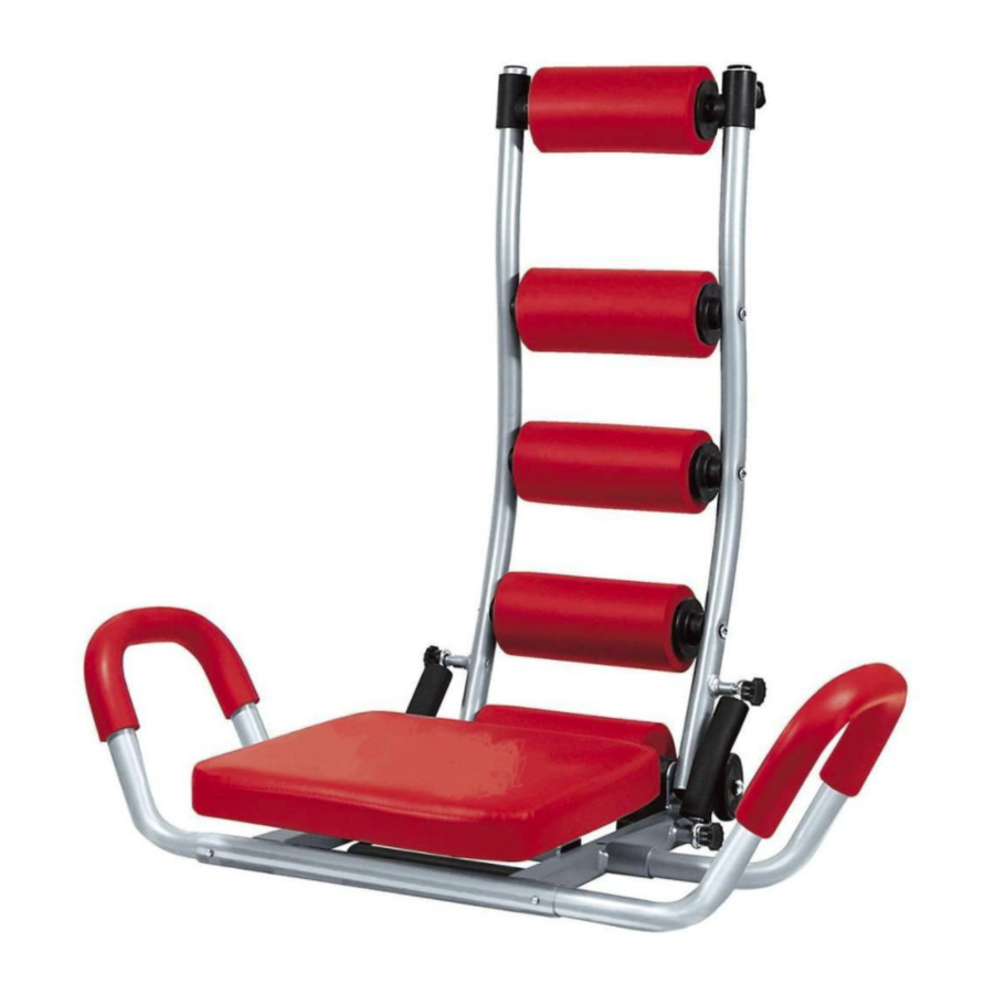
SEAT SWIVEL
The seat is designed so it can swivel in both
directions while exercising.
1. See Illustration 6A. If the exercise
requires the seat to swivel, simply pull up
the Pin and remove it.
2. See Illustration 6B. The seat will swing in
both directions.
3. If you need to secure the seat, move it to
its original (straight) position so both openings
of the right grip handle and seat are
lined up and insert the pin in.
CLICKER
The Ab Rocket Twister is equipped
with the Clicker located on the back
of the right back support metal bar.
When you complete a full ab crunch,
you will hear a click.
If you would like to remove the click
feature, see Illustration 7. Using the
screwdriver, remove both screws and
the clicker bracket. Now you will no
longer hear a click while doing
crunches.
STORAGE
For easy storage under the bed, simply remove both top Screw Tops by rotating them
counterclockwise, see Illustration 2 . Leave the bottom Screw Top attached. Bring the
Resistance Springs down, replace the Screw Tops. Bring down the Padded Back
Support. Both Grip Handles can be removed (if needed) for easy storage. Just press
the Spring Pins on both Grip Handles and remove them.
CUSTOMER SERVICE 1-800-423-4248
AB ROCKET TWISTER™ STYLE#: 8332
AB ROCKET™ and AB ROCKET TWISTER™ are trademarks of EMSON®
Distributed By EMSON NY, NY, 10001 ©Copyright 2010 EMSON
All Rights Reserved. Printed In China.
6A
6B
BACK OF UNIT (RIGHT SIDE)
7
CLICKER BRACKET
ASSEMBLY INSTRUCTIONS
Advertisement
Table of Contents

Subscribe to Our Youtube Channel
Related Manuals for AB Rocket Twister


Summary of Contents for AB Rocket Twister
- Page 1 Spring Pins on both Grip Handles and remove them. CUSTOMER SERVICE 1-800-423-4248 AB ROCKET TWISTER™ STYLE#: 8332 ASSEMBLY INSTRUCTIONS AB ROCKET™ and AB ROCKET TWISTER™ are trademarks of EMSON® Distributed By EMSON NY, NY, 10001 ©Copyright 2010 EMSON All Rights Reserved. Printed In China.
- Page 2 FIRST NOTE: AB ROCKET TWISTER™ unit needs to be assembled prior to use. Adjustable Head Support 1. See Illustration 1A. Locate the Padded Back Support piece. Insert it between the Metal Bars. Align with the openings. 2. See Illustration 1A. Attach Padded Back Support piece to the Metal Bars with screwdriver (included).
Need help?
Do you have a question about the Twister and is the answer not in the manual?
Questions and answers