Table of Contents
Advertisement
Quick Links
1. Speed
• ML-551x series : 55 ppm in Letter
• ML-651x series : 65 ppm in Letter
2. Printing Resolution
• Max. 1200x1200 dpi effective output
3. Processor
• SPGPV4 700 Mhz
4. Printer Language Emulations
• PCL, PS3
Service Manual
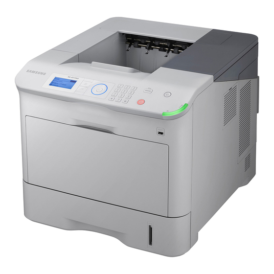
Mono Laser Printer
ML-551x/651x Series
5. Memory
• 256 MB default
• 256 MB / 512 MB (Optional Memory)
6. Interfaces
• One USB port, Two USB Host Port
• 1 GB Ethernet
• One IEEE 802.11 b,g,n wireless LAN (Optional)
7. Various optional units
• Finisher, Mailbox, SCF, HCF, HDD etc.
Advertisement
Table of Contents
Troubleshooting


Need help?
Do you have a question about the ML-651x series and is the answer not in the manual?
Questions and answers