Table of Contents
Advertisement
Quick Links
Solar water heating systems
Installation • Operation • Maintenance
CLI U12 SD0(W/L/F/P)118 El B/U
CLI U12 SK0(W/L/F/P)218 El B/U
CLI U12 SK0(W/L/F/P)318 El B/U
Solar with electric element back-up
CLI U12 SD0(W/L/F/P)119 HX B/U
CLI U12 SK0(W/L/F/P)219 HX B/U
CLI U12 SK0(W/L/F/P)319 HX B/U
Solar with heat exchanger back-up
CLI U12 SD0(W/L/F/P)1110 NG B/U
CLI U12 SK0(W/L/F/P)2110 NG B/U
Solar with natural gas back-up
CLI U12 SD0(W/L/F/P)1111 LP B/U
CLI U12 SK0(W/L/F/P)2111 LP B/U
Solar with propane back-up
The solar energy system described in this manual, when properly installed and maintained,
This certifi cation does not imply endorsement or warranty of this product by SRCC.
meets the minimum standards established by the SRCC.
CLI U12 SD0(W/L/F/P)118 AUX EL
CLI U12 SK0(W/L/F/P)218 AUX EL
CLI U12 SK0(W/L/F/P)318 AUX EL
Solar pre-heat to electric tank water heater
CLI U12 SD0(W/L/F/P)118 AUX GAS
CLI U12 SK0(W/L/F/P)218 AUX GAS
CLI U12 SK0(W/L/F/P)318 AUX GAS
Solar pre-heat to gas tank water heater
CLI U12 SD0(W/L/F/P)118 AUX TLG
CLI U12 SK0(W/L/F/P)218 AUX TLG
CLI U12 SK0(W/L/F/P)318 AUX TLG
Solar pre-heat to tankless gas water heater
Advertisement
Table of Contents

Related Manuals for Velux CLI U12 SD0(W/L/F/P) 118 El B/U

Summary of Contents for Velux CLI U12 SD0(W/L/F/P) 118 El B/U
- Page 1 Solar water heating systems Installation • Operation • Maintenance CLI U12 SD0(W/L/F/P)118 El B/U CLI U12 SD0(W/L/F/P)118 AUX EL CLI U12 SK0(W/L/F/P)218 El B/U CLI U12 SK0(W/L/F/P)218 AUX EL CLI U12 SK0(W/L/F/P)318 El B/U CLI U12 SK0(W/L/F/P)318 AUX EL Solar with electric element back-up Solar pre-heat to electric tank water heater CLI U12 SD0(W/L/F/P)119 HX B/U CLI U12 SD0(W/L/F/P)118 AUX GAS...
-
Page 2: Table Of Contents
− Installation check list Page – 6 Part 5: Specifi cations Page – 32 − VELUX solar water heating system with electric back-up Page – 7 − VELUX solar collector Page – 32 − VELUX solar water heating system with boiler back-up Page –... -
Page 3: Part 1: Product And Safety Information Page
Local installation regulation Installation of the VELUX solar water heating system may be governed by local rules and regulations for this type of product. The installation must be done in accordance with those regulations. Always use the latest edition of codes. The installation, adjustment, service and maintenance of the VELUX solar water heating system must be done by a licensed professional who is qualifi... -
Page 4: Part 2: General Information Page
The VELUX solar water heating system is designed to produce domestic hot water from either solar collectors, an electrical backup, a gas backup, or a boiler back up (provided by others). The VELUX systems can also be used as a solar preheat system to conventional electric, gas, or tankless water heaters (provided by others). -
Page 5: Solar Storage Tank Page
All VELUX solar water heating systems include a pump station controller that include the temperature and pressure gauges, check valves, ball valves, fl ow meter, fi ll and drain valves, and diff erential controller required to properly operate the VELUX solar water heating system. -
Page 6: Installation Check List Page
Part 3: Solar water heater system installation The Contractor shall obtain all required permits and approvals for installing the solar system. The installation shall conform to all federal, state and local regulations governing solar water heating system installations. The contractor shall adhere to sound building safety and trade practices. - Page 7 For all electric back-up models, make sure solar storage tank is fully purged of air before power is turned on to the back-up heat source. VELUX solar water heating system with electric or gas back-up – Part 3: Solar water heater system installation – 7...
-
Page 8: Velux Solar Water Heating System With Boiler Back-Up Page
VELUX solar water heating system with boiler back-up System models: CLI U12 SD0(W/L/F/P) 119 HX B/U CLI U12 SK0(W/L/F/P) 219 HX B/U CLI U12 SK0(W/L/F/P) 319 HX B/U 1. Collectors 2. Flashing/racking 3. Connector tube 4. Flextubes 5. Air Separator 6. -
Page 9: Velux Solar Pre-Heat Water Heating System Page
VELUX solar pre-heat water heating system System models: CLI U12 SD0(W/L/F/P)118 AUX EL CLI U12 SD0(W/L/F/P)118 AUX GAS CLI U12 SD0(W/L/F/P)118 AUX TLG CLI U12 SK0(W/L/F/P)218 AUX EL CLI U12 SK0(W/L/F/P)218 AUX GAS CLI U12 SK0(W/L/F/P)218 AUX TLG CLI U12 SK0(W/L/F/P)318 AUX EL CLI U12 SK0(W/L/F/P)318 AUX GAS CLI U12 SKO(W/L/F/P)318 AUX TLG 1. -
Page 10: Velux Solar System Components Page
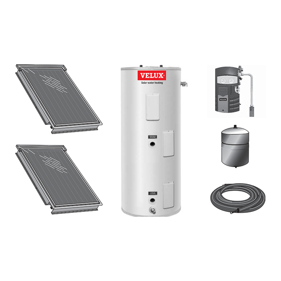
VELUX solar system components Listed below are the components needed for installation of the VELUX water heating system. 1. VELUX solar collector: Absorbs the sun’s energy and transfers this energy into the heat exchanger located on the bottom of the solar storage tank. - Page 11 Ball valve (for circulator): Used to isolate the circulator pump for service and when fi lling the system with heat transfer fl uid. VELUX solar system components – Part 3: Solar water heater system installation – 11...
-
Page 12: Other System Components
VELUX fl exible piping: Pre-insulated corrugated stainless steel fl exible piping designed specifi cally for VELUX solar loop piping. VELUX has designed a special cone shaped fi tting which ensures a tight and Tank temperature sensor secure connection to collectors without requiring a gasket or o-ring seal. -
Page 13: Solar Collector Orientation Page
Solar collector orientation Operating your VELUX solar water heater for optimal effi ciency is based on the correct orientation, pitch, and location of the solar collectors. In North America, collectors should be oriented due south, however may be oriented up to 45 degrees east or west of due south with minimal losses in solar gain. -
Page 14: Collector Location On 16" O.c. Rafters Page
Collector location on 16” o.c. rafters CLI U12 4000 • 2 Collector layout • 16” o.c. rafters CLI U12 4000 • 3 Collector layout • 16” o.c. rafters 14 – Part 3: Solar water heater system installation – Collector location on 16” o.c. rafters... - Page 15 Collector location on 24” o.c. rafters CLI U12 4000 • 2 Collector layout • 24” o.c. rafters CLI U12 4000 • 3 Collector layout • 24” o.c. rafters Collector location on 24” o.c. rafters – Part 3: Solar water heater system installation – 15...
- Page 16 3. Mark off the location for the fl exible piping penetration locations. Verify that there are no roof joists or obstructions prior to drilling, then drill, or cut openings for piping penetrations. 4. Carefully place collectors on roof. Place collector against temporary support and align them so that the fl exible piping connections align with the openings cut into the roof deck.
- Page 17 fi xed length and are not to be cut -- the cone shaped end connections on these pipes are designed specifi cally for use with VELUX collectors. Route the ZFR pipes between the collectors and attach to collectors. Secure nuts securely using wrench.
- Page 18 Locate the collector temperature sensor, couplant tube, and extension cable. Locate the collector temperature sensor well in the top left corner of the collector bank (collector with “hot” pipe connected). Fill the collector sensor port with couplant and then insert sensor into the sensor well. Secure the sensor in place with insulating tape. 10.
-
Page 19: Flashing Installation Page
fl ashing instructions. Do not drive roofi ng nails, screws, or other fasteners, through the fl ashings to secure. 2. Install the fi rst course of roofi ng material and VELUX fl ashings along left side of collector bank. Repeat procedure along right side of collector bank. -
Page 20: Solar Storage Tank And Pump Station Controller Location Page
The components on the potable side of the system may require future service or maintenance, so it is recommended that the connections be made with brass unions. You must use the VELUX pipe and fi ttings in plumbing the solar loop for the solar storage tank and the expansion tank. -
Page 21: Inspection Of Solar Storage Tank Page
Solar storage tank and pump station controller installation The design and installation of the VELUX solar water heating system should be done by qualifi ed individuals that have been trained in the proper installation techniques for VELUX solar water heating systems. It is important that good design and installation practice be followed to assure that your system will operate properly. -
Page 22: Solar Loop Piping To Collectors Page
Solar loop piping to collectors 1. Locate the collector hot supply fl exible pipe (with red tab) -- the hot supply pipe must be cut to length using a tubing cutter and connected to the microbubble air separator mounted to the pump station controller. Locate the collector cold supply fl... -
Page 23: Tank Temperature Sensor Installation Page
Tank temperature sensor installation 1. Remove the tank temperature sensor cover and insulation from the temperature sensor well located in the lower section of the solar storage tank. Remove the locking nut from the tank temperature sensor stud and clean any insulation material from the tank surface. 2. -
Page 24: Boiler Back-Up Heat Exchanger Connection
Boiler back-up heat exchanger connection (VELUX solar water heating system with boiler back-up only) The boiler heat exchanger connections are located in the front of the solar storage tank. Use a minimum 1” nominal tube size, wherever you are using zone valves or circulators. The inlet of the circulator is to be connected to the hot outlet side of the boiler. -
Page 25: Velux Solar Water Heating System With Electric Back-Up
Electrical connection (VELUX solar water heating system with electric back-up only) WARNING Tank must be fi lled with water before unit is turned on! The heating element will be damaged if energized for even a short period of time while tank is dry! CAUTION Be sure to ground the water heater. -
Page 26: Potable Water Piping
The propylene glycol heat transfer fl uid provided acts as a freeze protection fl uid and must be used to protect the system from freezing. The VELUX propylene glycol provided is rated as nontoxic. A 40% propylene glycol/60% water mixture should be used, however, you must use a mixture most appropriate for your climate. -
Page 27: Thermostat Adjustment
DANGER DANGER DANGER Water temperature over 125 degrees F. can cause severe burns instantly, or death from scalds. Children, disabled, and elderly are at highest risk of being scalded. See instruction manual before setting temperature at water heater. Feel water before bathing or showering! Temperature limiting valves are available. -
Page 28: Commissioning The Solar System
Commissioning the solar system Prior to fi lling the solar collectors with heat transfer fl uid, ensure that the collectors have been covered for a minimum of 1 hour. The solar loop piping should be pressure tested with air (40 psi) and checked for leaks before you pressurize the solar collector loop with glycol. -
Page 29: Programming System Controller
Programming system controller After the glycol loop has been charged the controller must be set to the desired settings. The solar control comes programmed with default settings for backup electric or solar preheat systems. The controller is operated by three push buttons located below the display. - Page 30 Vacation planning Solar water heaters can build up very high temperatures when there is no daily draw on the system. Your VELUX solar water heating system controller is programmed to protect your system from overheating. When leaving your home for extended periods of time, no special shut down procedures are required.
-
Page 31: Estimated Life Of Components
Estimated life of components Proper care and maintenance of your solar system will determine the life expectancy of the individual components of the system. Refer to the manufacturers’ warranty of the individual components for warranty coverage. To obtain warranty service, call your local service or installing contractor. WARNING Following installation of the T &... -
Page 32: Part 5: Specifi Cations
Part 5: Specifi cations VELUX solar collector Width Height Depth Measurements (inches) Code Code Gross 54.1 46.2 32.0 72.0 47.5 56.2 Frame 52.8 44.9 30.7 70.7 46.2 54.8 Glass 51.5 43.6 29.4 69.4 44.9 53.5 Aperture 49.5 41.6 27.4 67.4 42.9... -
Page 33: Velux Fl Extubes And Connections
0.24 Material, pipe Stainless steel / AISI 316 TI Material, insulation Foam EPDM Temperature limit, insulation (deg F) + 350 to - 40 F Insulation value (w/mK) 0.04 VELUX fl extubes and connections – Part 5: Specifi cations – 33... -
Page 34: Velux Glass Lined Solar Storage Tanks
VELUX glass lined solar storage tank (with electric back-up) • Glass lined steel tank • Dual backup heating elements • Two protective aluminum anode rods • Direct heat transfer with immersed incoloy elements • R-value of R-17 • T&P relief valve – included •... - Page 35 Toxic chemicals, such as those used for boiler treatment, shall NEVER be introduced into the potable side of this system. The potable side may NEVER be connected to any existing heating system or component(s) previously used with a non-potable water heating appliance. VELUX glass lined solar storage tank (with back-up heat exchanger) – Part 5: Specifi cations – 35...
- Page 36 VELUX glass lined solar storage tank (with gas backup) • Glass Lined Steel Tank • Flammable Vapor Ignition Resistant technology (FVIR) (TFF 060 2205 and TFF 060 3205) • Two Protective Aluminum Anode Rods • Backup Low NOx Burner (Ultra Low NOx Burner with •...
-
Page 37: Velux Solar Pump Station
320 °F VELUX solar pump station component technical data Pressure relief valve 87 psi Pressure gauge 0 - 87 psi Temperature gauges 250 °F Flow meter 0.5 - 3.5 gpm VELUX solar pump station – Part 5: Specifi cations – 37... -
Page 38: Velux Heat Transfer Fl Uid - Inhibited Propylene
fl uid should be pumped into suitable containers located in diked areas. Residual material should be cleaned up with water. Concentrate can be handled according to local, state, and federal regulations. 38 – Part 5: Specifi cations – VELUX heat transfer fl uid – Inhibited propylene glycol-based heat transfer fl uid... -
Page 39: Propylene Glycol Emergency Overview
Propylene glycol emergency overview Potential health eff ects Exposed to Potential health eff ects First aid May cause slight transient (temporary) eye irritation. Corneal injury is unlikely. Mists may cause Flush eyes with plenty of water. eye irritation. Prolonged contact is essentially non-irritating to skin. - Page 40 Part 6: Component lists VELUX solar system kits Parts breakdown System models System component Part number Quantity Collector CLI U12 4000 CLI U12 SD0L 118 El B/U CLI U12 SD0L 118 AUX EL Flashing system EDL U12 0000 CLI U12 SD0L 118 AUX GAS...
-
Page 41: Parts Breakdown
Pump station controller kit 307354 Collector CLI U12 4000 Flashing system EKL U12 0021E CLI U12 SK0W 2111 LP B/U Storage tank TFF 080 3205US Pump station controller kit 307355 VELUX solar system kits – Part 6: Component lists – 41... - Page 42 VELUX solar system kits Parts breakdown System models System component Part number Quantity Collector CLI U12 4000 CLI U12 SD0F 118 El B/U CLI U12 SD0F 118 AUX EL Rack system ZFT 101 CLI U12 SD0F 118 AUX GAS Storage tank...
- Page 43 Pump station controller kit 307354 Collector CLI U12 4000 Rack system ZFT 100 CLI U12 SK0P 2111 LP B/U Storage tank TFF 080 3205US Pump station controller kit 307355 VELUX solar system kits – Part 6: Component lists – 43...
-
Page 44: Velux Pump Station Controller
VELUX pump station controller Parts breakdown Item # Part Number Description QTY. 307341 Ball valve w/check valve, collector supply 307342 Ball valve w/check valve, collector return 307343 Safety valve and pressure gauge assy 307344 Deaerator 307345 Circulation pump 307346 Gasket 1/2"... - Page 45 Part 7: Troubleshooting Nature of trouble Possible cause Service Improper wiring. Check controller and tank wiring. a. Shorted wiring. Replace or repair. Provide adequate circuit or reduce b. Circuit overloaded. No Power – blown load. fuse or circuit breaker c. Improper wiring. Rewire per wiring diagram.
- Page 46 Nature of trouble Possible cause Service No power to pump. Check controller and pump wiring. Check program - Refer to pump station Controller improperly set. manual “Control parameter” section. Pump does not operate (even though there is solar radiation and Sensor out of position.
- Page 47 Unauthorized alterations to this system could result in a hazardous health condition. Be extremely careful when draining this fl uid. It may be discharged at a very high temperature and/or pressure. Instructions – VELUX solar SRCC OG-300 label set – 47...
- Page 48 Maintenance notes Notes 48 – Maintenance notes – Notes...
- Page 49 Service Information Installer information Installers name: Company: Address 1: Address 2: City: State: Zip: Phone number: Fax number: E-mail: Installation information Collectors: Model number: Serial number: Tank: Gallons: Aux: Orientation: Pitch: Installed date: Installer information – Service Information – 49...
- Page 50 XUS 20142-0108 VELUX America Inc. ©2008 VELUX Group 450 Old Brickyard Road • PO Box 5001 • Greenwood, SC 29648-5001 VELUX, VELUX logo are registered trademarks ® Tel 1-866-99-VELUX • Fax 1-864-943-2631 • www.veluxusa.com/solar...
Need help?
Do you have a question about the CLI U12 SD0(W/L/F/P) 118 El B/U and is the answer not in the manual?
Questions and answers