Table of Contents
Advertisement
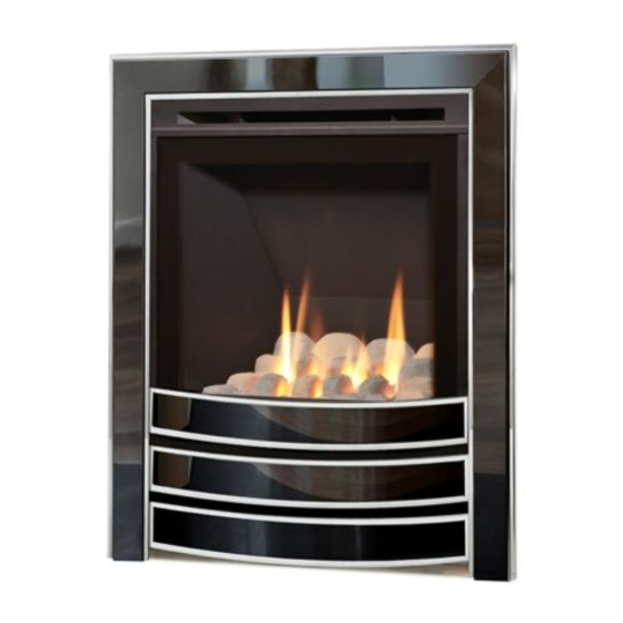
Midas HE
HIGH EFFICIENCY FUEL EFFECT GAS FIRE
Installation, Maintenance & User Instructions
Hand these instructions to the user
Model No's NSHC**MN, NSHP**MN, NSHC**SN & NSHP**SN are for
use on Natural Gas (G20) at a supply pressure of 20 mbar in G.B. /
I.E.
** denotes trim and fret variant fitted to product
Advertisement
Table of Contents

Related Manuals for Verine Midas HE


Summary of Contents for Verine Midas HE
- Page 1 Midas HE HIGH EFFICIENCY FUEL EFFECT GAS FIRE Installation, Maintenance & User Instructions Hand these instructions to the user Model No’s NSHC**MN, NSHP**MN, NSHC**SN & NSHP**SN are for use on Natural Gas (G20) at a supply pressure of 20 mbar in G.B. / I.E.
-
Page 2: Table Of Contents
CONTENTS Section 1 Information and Requirements PAGE Appliance Information Conditions of Installation Flue and chimney suitability Fireplace / surround suitability Shelf position Chimney inspection Fire place opening / catchment space Fitting to Chair bricks Precast Flues Metal Flue boxes 1.10 Hearths 1.11 Spillage Monitoring System... -
Page 3: Information And Requirements Page
SECTION 1 INFORMATION AND REQUIREMENTS APPLIANCE INFORMATION Model NSHC**MN / NSHP**MN / NSHC**SN / NSHP**SN ** denotes trim & fret variant of product Manual Control Slide Control Gas Type Main injector (1 off) Size 152 Size 146 Pilot Type Aeromatic Self SIT NG 9055 ODS Vitiating Burner Max. -
Page 4: Conditions Of Installation
INSTALLATION REQUIREMENTS CONDITIONS OF INSTALLATION It is the law that all gas appliances are installed only by a GAS SAFE Registered Installer, in accordance with these installation instructions and the Gas Safety (Installation and Use) Regulations 1998 as amended. Failure to install appliances correctly could lead to prosecution. -
Page 5: Fireplace / Surround Suitability
FIREPLACE / SURROUND SUITABILITY The fire must only be installed on a hearth it must not be installed directly onto carpet or other combustible floor materials. The fire is suitable for fitting to non-combustible fire place surrounds and proprietary fire place surrounds with a temperature rating of at least 150 o c. -
Page 6: Fire Place Opening / Catchment Space
There must be no leakage of smoke through the structure of the chimney during or after the smoke pellet test and it is important to check inside upstairs rooms adjacent to the chimney / flue. Check the chimney pot / terminal and general condition of the brickwork or masonry. - Page 7 Table A - Installation Depth Requirements for a Verine Midas HE being installed into a brick built chimney, requiring 12.0 litres of debris collection volume (fig. 2). Opening Width (mm) Minimum Depth Required (mm) 330 (minimum opening width) 440 (maximum opening width) For example, if the appliance was to be fitted into a 400mm wide opening, the depth required would be 135mm.
-
Page 8: Fitting To Chair Bricks
1.7 FITTING TO FIREPLACES WITH EXISTING CHAIRBRICKS AND CONVENTIONAL BRICKBUILT CHIMNEYS This appliance is suitable for use in fireplaces fitted with an existing chairbrick without the need for removal of the chairbrick, providing the minimum depth of the fireplace exceeds 175mm. If the depth is less than 175mm then the chairbrick must be removed. -
Page 9: Hearths
1.10 HEARTHS This appliance must only be installed on to a concrete or non-combustible hearth. The hearth material must be a minimum thickness of 12mm with the top surface at least 50mm above the floor. The hearth must be fitted symmetrically about the fire opening and have a minimum width of 760mm and a minimum projection of 300mm forwards from the fire opening. -
Page 10: Installation Of Fire
SECTION 2 INSTALLATION OF FIRE UNPACKING THE FIRE Carefully lift the fire out of the carton. Remove the loose item packaging carefully from the front of the appliance. Check the contents as listed :- Packing Check List - Coal Fuelbed Models 1 off Fire box / burner assembly 1 off... - Page 11 Proceed as follows for all models, (manual control model shown) :- Remove the top glass panel retaining trim which is held in position by 5 off screws as shown below in Fig. 3 Remove the left hand glass retaining trim as which is held in position by 3 screws as shown below in Fig.
- Page 12 For all manual control models proceed as follows :- Remove the two screws at the bottom of the control panel. See fig. 4 below. Remove the three screws from the fuel-bed base support as shown below also in Fig. 4 Fig.
- Page 13 For all Slide Control models proceed as follows :- Remove the burner. To allow burner removal, the control lever operating cable must be removed. The control lever operating cable can be seen running across the base of the fire, below the burner. To release the cable, unscrew the cable securing screw located in the centre of the aluminium operating arm and pull the cable out from its fixing hole.
- Page 14 Continue as follows for all models :- Ensure that the hearth is protected from damage and carefully lift the fire box into the fire opening, then slide it back into position. Check that the fire box flange fits flush to the sealing face of the fire surround or wall with no gaps present.
- Page 15 IMPORTANT : Sealing of the Gas Inlet Apertures In line with current regulations, it is imperative that the gas supply inlet aperture that is utilised during the installation is sealed with the grommet as supplied in the loose items pack. The product is manufactured with 3 knock out gas inlets in the firebox wrap to allow a left hand, right hand or rear gas inlet supply to the inlet elbow.
- Page 16 Carefully withdraw the fire box from the opening to enable the gas supply and fire fixing to be completed. There is a choice of methods of fixing the firebox which are provided to enable the installer to deal with any type of installation. The preferred method of fixing which is suitable for almost all situations is the cable fixing method which is described in the following section in detail.
- Page 17 downwards through the pair of fixing eyes on the same side of the fire. Thread the free end of the cables through the corresponding circular hole on each side of the lower rear of the fire. Carefully slide the fire box back into the fire opening and pull both cables tight.
-
Page 18: Gas Tightness And Inlet Pressure (Manual Control Models)
The other firebox fixing method is as follows :- In installations where the cable method is not suitable (e.g. loose masonary in rear of fire opening) the firebox can be secured to the fire surround using four screws and wall plugs (not provided). Below (Fig. 13) is a diagram to indicate the hole centre positions available on the firebox to facilitate the screw fixing to the fire- place / surround. -
Page 19: Gas Tightness And Inlet Pressure (Slide Control Models)
GAS TIGHTNESS AND INLET PRESSURE (SLIDE CONTROL MODELS). Remove the pressure test point screw from the pressure test point and fit a manometer. Turn on the main gas supply and carry out a gas tightness test. Depress the control lever to the position marked pilot. Hold down the control lever for a few seconds to purge the pipe work. -
Page 20: Fitting The Coal Fuelbed
SECTION 3 Fitting the Coal Fuelbed (where applicable) Place the coal fuelbed centrally on to the fuelbed support and push fully backwards to the rear face of the fibre boards Make sure that the fuelbed base is located centrally in the fire box. See Fig. 14 below. Fig. -
Page 21: Fitting The Trim
Warning : Use only the coal or pebble fuel-bed supplied with the fire. When replacing the coal or pebble fuel-bed remove the old coal or pebble fuel-bed and discard it. Fit a complete coal or pebble fuel-bed from the manufacturer, only use genuine replacements. -
Page 22: Fitting The One Piece Fascia
FITTING THE ONE PIECE FASCIA (WHERE APPLICABLE) Fit the outer trim assembly to the firebox with the magnets provided. NB. The fret is a loose item and located beneath the trim assembly. LIGHTING THE APPLIANCE (Manual Control Models) Turn on the gas isolation tap. Depress the control knob and turn anti-clockwise to the position marked ignition / low rate. -
Page 23: Lighting The Appliance (Slide Control Models)
LIGHTING THE APPLIANCE (Slide Control Models) Turn on the isolation valve at the restrictor elbow if necessary. Depress the control lever fully downwards to the position marked “Z” Hold down the control lever for a few seconds to allow the gas to reach the pilot. (See Fig. -
Page 24: Checking For Clearance Of Combustion
CHECKING FOR CLEARANCE OF COMBUSTION PRODUCTS Close all doors and windows in the room. Light the fire and allow to run for approximately 5 minutes on high position. After approximately 5 minutes hold a smoke match just inside and below the centre of the lower front edge of the top of the fire, as shown below in Fig. -
Page 25: Maintenance
Servicing Notes Servicing should be carried out annually by a competent person such as a GAS SAFE registered engineer. This is a condition of the Verine guarantee schemes. The service should include visually checking the chimney and fire opening for accumulations of debris and a smoke test to check for a positive up-draught in the chimney. -
Page 26: Removal Of The Control Tap (Manual Control Models)
Removing the Control Tap from the fire. 4.3.1 Remove the burner assembly as in section 4.1. 4.3.2 Pull the control knob off the control tap spindle. 4.3.3 Loosen and remove the two gas pipe retaining nuts from the control tap and release the ends of the gas pipes from the control tap body. Remove the push in thermocouple from the end of the control tap. -
Page 27: Removal Of The Burner Assembly (Manual Control Models)
Slide Control Fires - For Diagrams refer to section 2 Removal of the burner assembly (SC models) 4.5.1 Prepare the work area (lay down dust sheets etc,) 4.5.2 Remove the trim. Lift the fender and ash pan cover out of the way and put them in a safe location. -
Page 28: Removal Of The Battery Ignitor (Slide Control Models)
Refit the burner heat shield then refit the coals / pebbles referring to section 3 for the correct coal / pebble layout. Refit the glass panel and glass panel retaining trims. The fender and ash pan cover or fascia can now be re-positioned. -
Page 29: Replacing The Control Cable (Slide Control Models)
Replacing the Control Cable (SC models) 4.9.1 The control lever operating cable Fig. 18 can be seen running across the base of the fire, below the burner. To release the cable, unscrew the cable securing screw located in the centre of the aluminium operating arm and pull the cable out from its fixing hole. - Page 30 Replacement of any other parts must be carried out by a competent person such as a GAS SAFE registered gas installer. The part numbers of the main replaceable parts are as follows, these are available from your local Verine stockist, whose details can be found on the BFM Europe website, in the “stockist”...
-
Page 31: Conditions Of Installation / About Your New Gas Fire
SECTION FIVE - USER INSTRUCTIONS 5.1 Installation Information Conditions of Installation It is the law that all gas appliances are installed only by a competent (e.g. GAS SAFE) Registered Installer, in accordance with the installation instructions and the Gas Safety (Installation and Use) Regulations 1998. Failure to install appliances correctly could lead to prosecution. - Page 32 About your Verine Midas HE The Verine Midas HE range of coal & pebble fuel-bed gas fires incorporates a unique and highly developed fuel bed which gives the realism of a loose coal or pebble layout combined with realistic flames and glow. The use of durable ceramic material in the construction of the fuel-bed components ensures long and trouble free operation.
-
Page 33: Operating The Fire (Manual Control Models)
The ceramic fuel-bed remains hot for a considerable period after use and sufficient time should be allowed for the fire to cool before cleaning etc. The fire must only be operated with the trim and fret supplied with the fire. 5.2 Operating the Fire (manual control variants) The controls are located behind the ashpan cover which is situated below the fret or contemporary ashpan cover. -
Page 34: Operating The Fire (Slide Control Models)
5.3 Operating the Fire (slide control models) The controls comprise a control lever, to turn the fire on and off and adjust the gas rate. The control lever is located at the top right hand side of the fire. Depressing the control lever fully operates the igniter and lights the pilot flame. - Page 35 Depress the control lever fully downwards to the position marked “Z”. Hold in position for a few seconds to allow the gas to reach the pilot. Insert the tip of a lit taper or spill at the pilot head (LHS of burner) This will light the pilot flame and low rate gas.
-
Page 36: Removal / Replacement Of The Coal Fuelbed
Removal / Replacement of the Coal Fuelbed (where applicable) Remove the trim / fret or fascia as applicable. Remove the top, left hand & right hand glass panel retaining trims, which are held in position by 11 off screws, then lift the glass panel clear. Place the coal fuelbed centrally on to the fuelbed support and push fully backwards to the rear face of the fibre boards. - Page 37 Warning : Use only the coal or pebble fuel-bed supplied with the fire. When replacing the coal or pebble fuel-bed remove the old coal or pebble fuel-bed and discard it. Fit a complete coal or pebble fuel-bed from the manufacturer, only use genuine replacements.
-
Page 38: Cleaning The Fire
Cleaning the Fuelbed We do not recommend cleaning of the coals or fuelbed components as these are fragile and damage may result. None of these parts must be washed or exposed to any cleaning agents or water. Any damaged parts must be replaced by contacting your dealer or telephoning BFM Europe Ltd. -
Page 39: Bfm Europe Ltd.trentham Lakes
Due to our policy of continual improvement and development the exact accuracy of descriptions and illustrations cannot be guaranteed. Part no. B-131080 Issue 5 BFM Europe Ltd. Trentham Lakes Stoke-on-Trent Staffordshire ST4 4TJ www.bfm-europe.com Telephone - General Enquiries : (01782) 339000 Telephone - Service : (0844) 7700169...
Need help?
Do you have a question about the Midas HE and is the answer not in the manual?
Questions and answers