Table of Contents
Advertisement
Advertisement
Table of Contents

Subscribe to Our Youtube Channel
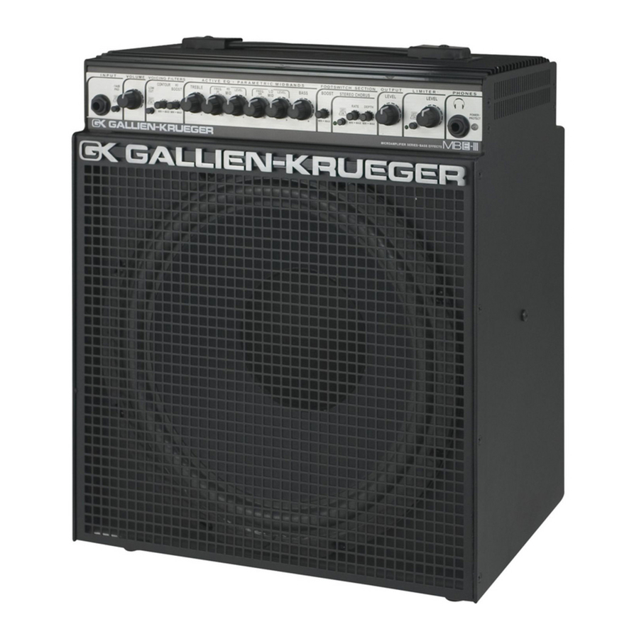
Summary of Contents for Gallien-Krueger MB150S
- Page 1 Service Manual Micro Bass Series...
- Page 2 Table of Contents Operating Instructions Turn On / Calibration Procedures Schematics Engineering Change Orders (ECOs) 33 Bill of Materials...
- Page 8 MB150S Preamp Turn-On Procedure GK Document # 420-0061-A / Preamp Board #206-0061-C Model- MB150S- All Options Revised 7/26/99 SETUP 1) Power switch off- connect power cord. 2) Connect “power” 3-pin connector to P1 on MB-S board so that it clicks into position.
- Page 9 INPUT SET-UP AND SYSTEM GAIN TEST (contd.) 9) Decrease limiter level to 0. Output drops to 12Vrms. 10) Disengage limiter. 11) Look at tip of headphone jack (J4). Output should be about 4.2Vrms at this point. 12) Repeat step 11 looking at ring of headphone jack. TONE CONTROLS TEST 1) Set all large knobs to center (12 o’clock), switches out, small knobs to 0.
- Page 12 MB150E Preamp Turn-On Procedure GK Document #: 420-0087-A / Preamp Board # 206-0087-B Model #’s: MB150E- All options Rev. 7/27/99 SETUP 1) Power switch off - connect power cord. 2) Connect “power” 3-pin connector from power amp to connector P1 on MB-E board. The colors should read (bottom-top): black, violet, and brown.
- Page 13 INPUT SET-UP AND SYSTEM GAIN TEST(contd.) 8) Disengage limiter. 9) Look at tip of headphone output jack (J4). Output should be about 1Vrms at this point. 10) Repeat step 9 looking at ring of headphone output jack. TONE CONTROLS TEST 1) Set all large knobs to center (12 o’clock), switches out, small knobs to 0.
- Page 14 RETURN AND STEREO AUX IN TEST 1) Set AC-VM to 10V scale. 2) Set oscillator to 100 sine wave at –26dBV (50mV). 3) Insert plug from oscillator into return jack (J6). 4) Set output to 10. Output = 2Vrms. 5) Insert plug from oscillator half-way into stereo aux. in jack (J5). Output = 3.5Vrms. 6) Push plug in rest of way.


Need help?
Do you have a question about the MB150S and is the answer not in the manual?
Questions and answers