
Related Manuals for Gemtech GT5020


Summary of Contents for Gemtech GT5020
- Page 1 Install guide GT5020 Install guide GT5020...
- Page 2 Install guide GT5020 To avoid electrical shock and to prevent damage to the furnace, air conditioner, Caution and thermostat, disconnect the power supply before beginning work. This can be done at the circuit breaker, or at the appliance. You will need #1 Phillips screwdriver (small) and Tools Drill with 3/16-in.
- Page 3 This thermostat does not require leveling. Do not locate in unusual cooling conditions, such as: on a wall separating an unheated room; or in a draft from a stairwell, door, or window. Do not locate in a damp area. This can lead to corrosion that will shorten thermostat life.
- Page 4 2 Remove old unit IMPORTANT : LABEL ALL WIRES Switch electricity to the furnace and BEFORE DISCONNECTING THEM! air conditioner OFF; then proceed with the following steps. Remove cover from old thermostat. Most are snap-on types and simply pull off. Some have locking screws on the side or front.
- Page 5 3 Mount the GT5020 Separate front from back of unit. Press up on the catch on bottom of thermostat and swing the body away from the base, lift up to remove the body from the base. Hold the base against the wall, with the wires coming through the opening below the terminal block.
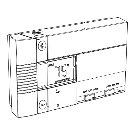
- Page 6 4 Gas-Electric Selection REFER to the back of the Control Unit If you have Electric Heat or a Heat Pump you must place the Gas/Electric jumper in the ELECT position (thermostat controls the Fan). If you have Gas Heat the Gas/Electric Jumper should be in the GAS position (furnace controls the Fan).
-
Page 7: Install Batteries
The batteries will last well over 1 year. If the batteries are not replaced the thermostat will stop working. 2) The GT5020 can run on the C wire if available. (24 VAC ONLY) As shown in the wiring diagrams, The C wire is the other side of the 24VAC heating transformer. If the... - Page 8 If you have a Zoned Heating/Cooling system with multiple thermostats, please refer to our website at www.Gemtech-thermostats.com for installation notes. Before you Connect Wires Please refer back to these guidelines for safe and secure wire connections.
- Page 9 Power wire (pwr) Y or B Turn Valve off Turn Valve on Note: On a heat pump, if O and B are both present, connect O to O and tape off B. For wiring support visit our website at www.Gemtech-thermostats.com...
- Page 10 A u x h e w it h o u t A u Go To Page 17 Go To Page 16 If you do not find the wiring information for your system try our website: www.Gemtech-thermostats.com.
- Page 11 8 Wire Connections cont When you have finished connecting the wires attach control unit to wall unit. Hook the top of the body onto the base, swing the body down, and snap the body onto the base. Follow these procedures to verify you 9 Check Unit have correctly installed the unit.
- Page 12 GT5020 Features The GT5020 can be used with most 24 volt gas, oil or electric heating and air conditioning systems, heat pumps or gas millivolt heating systems. It cannot be used with 120 volt heating systems. The GT5020 is digital. You can set your desired Heat and cool temperature set points directly on the Large LCD display.
- Page 13 2 WIRE a c e F r o m F u r n Thermostat jumper NOTE: Wires marked with wire the dotted line are optional. HEAT HEAT Power FURNACE STEP 1 - Connect the R (or RH) wire to the RH terminal on the thermostat.
- Page 14 3 WIRE Thermostat a c e F r o m F u r n jumper NOTE: Wires marked with wire the dotted line are optional. Heat Heat Power FURNACE STEP 1 - Connect the R (or RH) wire to the RH terminal on the thermostat.
- Page 15 a c e F ro m F u rn a n d A C u n 4 WIRE STEP 1 - Connect the Y wire NON-HEAT PUMP Thermostat to the Y terminal on the thermostat. This connects to the Cooler compressor. jumper wire STEP 2 - Connect the RH or R wire to the RH...
- Page 16 a c e F ro m F u rn 5 WIRE STEP 1 - Remove the Jumper wire. NON-HEAT PUMP a n d A C u n Thermostat STEP 2 - Connect the Y wire to the Y terminal on the thermostat. This connects to the Cooler compressor.
- Page 17 HEAT PUMP STEP 1 - Connect the G wire to p u m p F ro m h e a t w/o Auxiliary Heat w /o A u x h e the G terminal on the thermostat. jumper wire This connects the Fan. Thermostat STEP 2 - notice jumper wire between W and Y.
-
Page 18: Heat Pump
HEAT PUMP STEP 1 - Connect the G wire to with Auxiliary Heat p u m p F ro m h e a t the G terminal on the thermostat. w it h A u x h e jumper This connects the Fan. wire STEP 2 - notice jumper wire Thermostat... - Page 19 Notes -...
- Page 20 Customer Support website www.Gemtech-thermostats.com 1-507-013...
Need help?
Do you have a question about the GT5020 and is the answer not in the manual?
Questions and answers