Invacare Pronto M61 Service Manual
With surestep
Hide thumbs
Also See for Pronto M61:
- Operating and maintenance manual (80 pages) ,
- User manual (68 pages) ,
- Service manual (132 pages)

Related Manuals for Invacare Pronto M61


Summary of Contents for Invacare Pronto M61
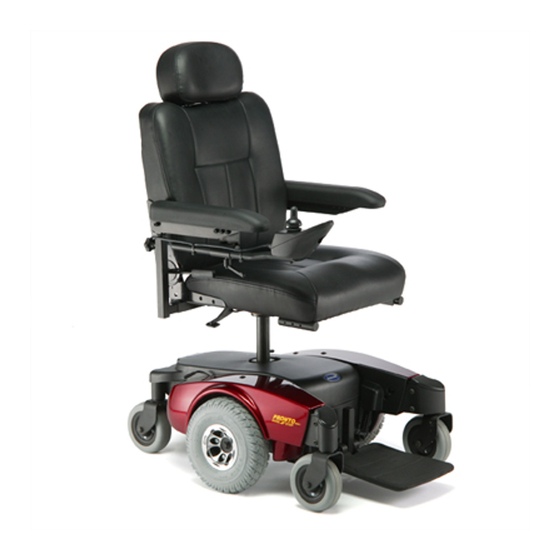
- Page 1 Invacare® Pronto™ M61 Series with SureStep® en Power Wheelchair Service Manual DEALER: Keep this manual. The procedures in this manual MUST be performed by a qualified technician.
- Page 2 All rights reserved. Republication, duplication or modification in whole or in part is prohibited without prior written permission from Invacare. Trademarks are identified by ™ and ®. All trademarks are owned by or licensed to Invacare Corporation or its subsidiaries unless otherwise noted.
-
Page 3: Table Of Contents
5 Settings and Adjustments ......23 Contents 5.1 Adjusting the seat depth ......23 5.2 Adjusting the seat height . -
Page 4: General
INVACARE. Gives useful tips, recommendations and information • If you have any problems or questions please contact Invacare for efficient, trouble-free use. Service. This product complies with Directive 93/42/EEC concerning medical devices. -
Page 5: Safety
– Changes to the drive program may only be carried out batteries and the seat. by trained Invacare specialist dealers. – Invacare supplies all mobility devices with a standard drive program ex-works. Invacare can only give a CAUTION! warranty for safe vehicle driving behavior - especially Injury hazard if the vehicle starts moving tipping stability - for this standard drive program. -
Page 6: Testing
30 to 40 amps from the batteries for 0.3 seconds. an open connection respectively. If either condition Performing this step puts a heavy load on the batteries exists, send the motor to Invacare Technical Service for as they try to push through the stationary object. If the inspection/repair. -
Page 7: Checking Battery Charge Level
Testing 3.5 Checking Battery Charge Level The following “Dos” and “Don’ts” are provided for your convenience and safety. DON’T Don’t perform any installation or maintenance without first reading Read and understand this manual and any service information that this manual. accompanies a battery and charger before operating the personal transporter. -
Page 8: Service
Invacare® Pronto™ M61 Series with SureStep® 4 Service Thread Tightening torque in Nm ±10% 120 Nm 4.1 Tightening torques 180 Nm CAUTION! Damage can be caused to the mobility device due UNC Thread Tightening torque in to improperly tightened screws, nuts or plastic Nm ±10%... -
Page 9: Battery
Ohm out motor to check for possible internal damage (worn out brushes may be possible). Power module power stage board or relays Replace power module or send to Invacare may be damaged for repair. Motor runs but loses power Power module senses heavy load and has Stop driving and let electronics cool. -
Page 10: Battery Charger
Check for AC power with digital volt meter. Damaged power cord Check for damage on the power cord, replace if damaged or send to Invacare for repair. Charger LED’s burnt out Replace charger. Charger may have internal fuse that is blown Remove charger cover and check for fuses. -
Page 11: Electrical System
Service Component Check Remedy Done • • Side panels Damage to side panels. Replace side panels if damaged. • • Side panel fixings. Tighten screws. • • Replace seat lock. Seat lock Seat lock defective. • • Seat angle adjustment Tight seating of SL fuses. -
Page 12: Use The Correct Batteries
Invacare® Pronto™ M61 Series with SureStep® 4.3.3 Connecting/Disconnecting battery cables WARNING! Risk of injury or damage due to electrical shorts. – Never allow any of your tools and/or battery cables to contact both battery terminals at the same time. – Connect same color connectors to each other (red to red, black to black). -
Page 13: Cable Routing
Service Slide terminal caps up onto the battery cables. 12. Assemble all parts again in reverse order. Disconnect positive (+) battery cable H from the positive (+) 13. Test all functions of the mobility device. battery terminal F. Disconnect negative (-) battery cable B from negative (-) battery 4.4 Drive components terminal C. -
Page 14: Removing/Installing The Motor
Invacare® Pronto™ M61 Series with SureStep® Grasp the motor engaging lever by the end that attaches to the motor lock. Remove the three long screws D and three short screws E and F securing the motor to the walking beam. -
Page 15: Electronics
Service 4.5 Electronics 4.5.1 Disconnecting/Connecting the remote Release the tension on the brush spring retainer F with a small screwdriver G and position the screwdriver in place to hold the spring retainer. Remove the motor brush and perform the following: Inspect the commutator (not shown) for damage. -
Page 16: Repositioning The Remote Mounting Bracket
Invacare specialist dealers. Slide remote mounting tube through the mounting bracket to the – Invacare can only give a warranty for safe mobility desired position and secure with the clamping lever. device driving behavior — especially the tipping stability —... -
Page 17: Wheels
Apply lubricant to drive shaft E and keystock F. The drive programs for mobility devices are continually being further developed and improved by Invacare. For this reason, you Align the keystock in the drive shaft with the cutout in the wheel hub and position the wheel D on to the drive shaft. -
Page 18: Removing/Installing The Front/Rear Caster Assembly
Invacare® Pronto™ M61 Series with SureStep® Removing the caster assembly Remove the dust cover D with a flat screwdriver. Remove locknut C and washers B securing caster assembly to the steering head. Remove caster assembly. Installing the caster assembly Insert threaded post A of caster assembly into steering head. -
Page 19: Covers
Service Installing the top cover Pull the remote cable A through the center hole C in the top cover. Position the top cover D onto the frame E and push downward to engage the hook and loop straps F. Secure the remote cable using the clip B on the top cover. 4.7.2 Removing/Installing the side cover Remove the drive wheel. -
Page 20: Removing/Installing The Inner Cover
Invacare® Pronto™ M61 Series with SureStep® 4.7.4 Removing/Installing the inner cover Installing the pivot tube If necessary, insert the bushings D into each end of the pivot tube. Tools: Position the pivot tube E onto the pivot post F. •... -
Page 21: Center-Mounted Footboard
Service 4.9 Center-mounted footboard 4.10 Vari-A legrests WARNING! 4.10.1 Swivelling the footrest/legrest outward and/or After any adjustments, repair or service and removing before use, make sure that all attaching hardware is tightened securely - otherwise injury or damage The small unlocking button is located on the upper section of the may result. -
Page 22: Removing/Installing The Lifter Actuator
Invacare® Pronto™ M61 Series with SureStep® Removing the seat Pull the detent lever A up and turn the seat to one side. Remove the four screws D and washers E securing the lifter Prevent the seat from engaging with the seat post again. -
Page 23: Settings And Adjustments
Settings and Adjustments 5 Settings and Adjustments 5.1 Adjusting the seat depth Tools: • 5/32” Allen key Remove the seat. Refer to 4.11 Removing/Installing the seat, page 21. Remove the four screws A and washers B securing the seat pivot C and four 1–inch adjustment spacers D to the seat base E. - Page 24 Invacare® Pronto™ M61 Series with SureStep® Align the mounting holes on the seat pivot with the mounting holes on the seat base, that achieve the desired seat position. • 1–Inch back seat position E • Standard seat position F •...
-
Page 25: Accessories
Accessories Remove the two screws A securing the postural belt B to the 6 Accessories seat frame. Remove the two halves of the postural belt from the rear seat frame. 6.1 Replacing the postural belt Reposition the two new postural belt halves underneath seat rails. Reinstall the two screws that secure the postural belt to the Tools: seat frame. - Page 26 Notes...
- Page 27 Notes...
- Page 28 Invacare Sales Companies Australia: Ireland: New Zealand: Canada: Invacare Australia PTY. Ltd. Invacare Canada LP Invacare Ireland Ltd, Invacare New Zealand Ltd 1 Lenton Place, North Rocks NSW 570 Matheson Blvd E. Unit 8 Unit 5 Seatown Business Campus 4 Westfield Place, Mt Wellington 1060...
Need help?
Do you have a question about the Pronto M61 and is the answer not in the manual?
Questions and answers
testing motor off chair