
Related Manuals for PASCO ME-8930

Summary of Contents for PASCO ME-8930
- Page 1 Instruction Manual and 012-06734A 09/98 Experiment Guide for the PASCO scientific Model ME-8930 SMART TIMER © 1998 PASCO scientific $7.50...
- Page 2 Smart Timer 012–06734A...
-
Page 3: Table Of Contents
012–06734A Smart Timer Table of Contents Section Page Table of Contents ..........................i Copyright, Warranty, and Equipment Return ................ii Introduction ..........................1 Equipment........................... 3 Operating the Smart Timer ......................4 Smart Timer Modes of Operation ....................4 Quick Cross-Reference for Suggested Activities and Smart Timer Modes......5 Time Modes ........................ -
Page 4: Copyright, Warranty, And Equipment Return
To be certain the unit will not be damaged in PASCO will repair or replace at its option any part of shipment, observe the following rules: the product which is deemed to be defective in ➀... -
Page 5: Introduction
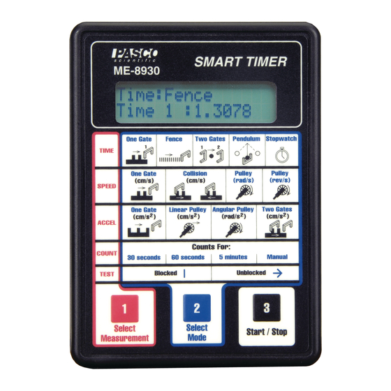
Smart Timer Introduction The PASCO ME-8930 Smart Timer is an accurate, versatile digital timer and measurement system for the student laboratory. The Smart Timer offers 0.1 ms timing resolution and an easy-to-use memory function. The Smart Timer measures several types of events detected with PASCO’s digital sensors, including speed and acceleration using... - Page 6 Smart Timer 012–06734A In One Gate Mode, a single photogate lets you measure the time, velocity, or acceleration of a fence as it passes through the photogate. Two photogates are used for collision experiments using one or two carts or for experiments where the velocity of a cart must be measured at two different points.
-
Page 7: Equipment
012–06734A Smart Timer Equipment Included: Smart Timer Smart Timer Picket Fences (2) 9 VDC adapter liquid crystal display mode illustrations connector for 9VDC adapter (side panel)) battery compartment on/off switch (bottom panel) (side panel) input channel 2 touchpad keys input channel 1 9 VDC adapter 5 cm fence 1 cm flag... -
Page 8: Operating The Smart Timer
4. Slide the power switch to the ON position. The Smart Timer will “beep” and show PASCO scientific on the display. From this point, the three-step setup of the Smart Timer is easy: 1. - Page 9 012–06734A Smart Timer...
-
Page 10: Quick Cross-Reference For Suggested Activities And Smart Timer Modes
Smart Timer 012–06734A summary of the mode suggested for a given experimental activity can be found on page 5 ➤ Note: The (Quick Cross-Reference for Suggested Activities and Smart Timer Modes). Refer to the picket fence timing diagrams in Table 1 (pages 8 and 9) for a detailed look at how the Smart Timers supplied with the times events on its input(s) and an explanation of how speed and acceleration calculations Smart Timer is... -
Page 11: Speed Measurement Modes
012–06734A Smart Timer cleared and the “*” reappears. This RESET-START-STOP sequence is repeated for ➤ Note: each new elapsed time. Whenever the “*” is not showing, the mode may be The stopwatch changed. function is not a precision timing Using the Alternate Timing Function: Connect an appropriate accessory to input mode and is channel #1 or #2. - Page 12 Table 1. Summary of Smart Timer Modes Type Modes Key Sequence* Timing Diagram** Calculation Algorithm One Gate Fence Two Gates Pendulum Stop Watch One Gate (cm/s) Collision (cm/s) Pulley (rad/s) Pulley (rev/s)
- Page 13 One Gate Linear Pulley Angular Pulley Two Gates 30 seconds 60 seconds 5 minutes Manual One Gate * The key sequences shown are valid in the initial or power-on situation only.
-
Page 14: Acceleration Measurement Modes
(positive number) and deceleration (negative number). Linear Pulley: In this mode, the Smart Timer converts rotary motion of a PASCO pulley to an equivalent linear acceleration in cm/s Angular Pulley: In this mode, the Smart Timer converts rotary motion of a PASCO... -
Page 15: Test Mode
9,999,999. Each count will be accompanied by a short beep. Used with a PASCO SN-7927 G-M Tube/ Power Supply, this mode is useful for group demonstrations to show the random nature of atomic disintegration and the inverse-square relationship between number of disintegration’s detected and distance from the radioactive source. -
Page 16: Caring For The Smart Timer
180 mA, maximum. Accessory Options The following PASCO accessories are available to help extend the utility of the Smart Timer. See the current PASCO catalog for more information. Accessory Photogate (ME-9204B): The stereo phone plug of the Accessory Photogate plugs into either of the phone jacks on the side of the Smart Timer, giving you the option of two identical photogates operating from a single timer. - Page 17 Smart Timer Time-of-Flight Accessory (ME-6810): The Timer-of-Flight Accessory facilitates the accurate measurement of the flight time of a ball launched by a PASCO projectile launcher. See page 33 (Time of Flight and Initial Velocity and Figure 9.1) for details of the setup.
-
Page 18: Troubleshooting
Smart Timer 012–06734A... -
Page 19: Experiment One: Acceleration Of Gravity
012–06734A Smart Timer Experiment One: Acceleration Due to Gravity EQUIPMENT AND MATERIALS REQUIRED • Smart Timer (ME-8930) • Smart Timer Picket Fence • Photogate (ME-9498A) Purpose The purpose is to determine the acceleration due to the Earth’s gravity. Theory The accepted value for the acceleration due to gravity on the Earth’s surface is 9.8 m/s With the Smart Timer, the acceleration due to Earth’s gravity can be quickly determined... - Page 20 Smart Timer 012–06734A 2. Insert the plug of the photogate into channel 1 or 2 of the Smart Timer, and set up the Smart Timer to measure Time, Fence. 3. Hold the Smart Timer Picket Fence in a position so it will drop vertically through the photogate and so the 5 cm fence will block the photogate beam as the fence drops through the photogate.
-
Page 21: Experiment Two: Newton’S Second Law
012–06734A Smart Timer Experiment Two: Newton’s Second Law EQUIPMENT AND MATERIALS REQUIRED • Smart Timer (ME-8930) • Photogate (ME-9498A) • Dynamics Cart (ME-9430 or ME-9454) • Photogate Bracket (part no. 003-04662) • Dynamics Cart Track (ME-9429A) • Mass Hanger and Mass Set (ME-9348) •... - Page 22 Smart Timer 012–06734A 5. Place the Dynamics Cart on the track, attach a string to the hole in the end of the cart, and tie a mass hanger on the other end of the string. The string must be just long enough so the cart hits the end stop before the mass hanger reaches the floor.
-
Page 23: Experiment Three: Conservation Of Momentum In Collisions
012–06734A Smart Timer Experiment Three: Conservation of Momentum In Collisions EQUIPMENT AND MATERIALS REQUIRED • Smart Timer (ME-8930) • (2) Photogate (ME-9498A) • Collision Cart with mass (2) (ME-9454) • (2) Photogate Bracket (Part No. 003-04662) • Dynamics Cart Track (ME-9429A) •... - Page 24 Smart Timer 012–06734A 3. Set up the Smart Timer to measure Speed: collision (cm/s). Press to activate the Smart Timer. ➤ Note: If the flags of both carts do not go through the photogate beams twice, the Smart Timer will not complete the timing cycle and display velocities automatically.
- Page 25 012–06734A Smart Timer Analysis 1. For each of the cases, calculate the momentum of each cart before the collision. Record the results in Table 3.2. 2. For each of the cases, calculate the total momentum of both carts before the collision. Record the results in Table 3.2.
- Page 26 Smart Timer 012–06734A Part B—Elastic Collisions Set up the carts so the magnetic ends face each other, so the carts will repel each other when they collide. Record the data in Tables 3.3 and 3.4. Equal Masses a. Place one cart at rest in the middle of the track. Give the other cart an initial velocity toward the cart at rest.
- Page 27 012–06734A Smart Timer Table 3.4 Results % of After p2 After TOTAL TOTAL Before Before Before After Difference Trial 1 Trial 2 Trial 3 Trial 4 Trial 5 Trial 6 Trial 7 Questions 1. Kinetic energy is not conserved in inelastic collisions but it is conserved in ideal elastic collisions.
- Page 28 Smart Timer 012–06734A...
-
Page 29: Experiment Four: Conservation Of Angular Momentum
• paper clips (for masses < 1 g) • Smart Pulley (ME-9387) • calipers • Smart Timer (ME-8930) Purpose The purpose of this experiment is to find the rotational inertia of a ring and a disk experimentally and to verify that these values correspond to the calculated theoretical values. - Page 30 Smart Timer 012–06734A To find the rotational inertia experimentally, a known torque is applied to the object and the resulting angular acceleration is measured. Since t = Ia, I = τ α where a is the angular acceleration, which is equal to a/r, and t is the torque caused by the weight hanging from the thread that is wrapped around the base of the apparatus.
- Page 31 012–06734A Smart Timer Setup 1. Place the disk directly on the center shaft as shown in Figure 4.3. The side of the disk that has the indentation for the ring should be up. 2. Place the ring on the disk, seating it in this indentation. 3.
- Page 32 Smart Timer 012–06734A least three times and record the average values for weight of the hanging mass and acceleration in Table 4.2. 3. Using calipers, measure the diameter of the pulley about which the thread is wrapped and calculate the radius. 4.
- Page 33 012–06734A Smart Timer Calculations Record the results of the following calculations in Table 4.3. 1. Subtract the “friction mass” from the hanging mass used to accelerate the apparatus to determine the mass, m, to be used in the equations. 2. Calculate the experimental value of the rotational inertia of the ring and disk together. 3.
- Page 34 Smart Timer 012–06734A...
-
Page 35: Other Suggested Experiments
012–06734A Smart Timer Other Suggested Experiments Note: The following experiments are in copy-ready form in the manual for the Dynamics Cart Accessory Track Set (manual number 012-05035) • Acceleration Down an Incline (Experiment 8): Use a Photogate and the Smart Timer instead of a stop watch (Figure 5.1). Adjust the height of the Photogate so the light path is intersected with the 5 cm fence of the Smart Timer fences. - Page 36 Smart Timer 012–06734A • Oscillations on an Incline (Experiment 4): Use a photogate and the Smart Timer instead of a stop watch, and use the ME-9471 Picket Fence spring ME-9471 (part number 648-04704), not the Picket Fence Smart Timer Picket Fence (Figure 7.1).
- Page 37 012–06734A Smart Timer Note: The following experiment is in copy-ready form in the manuals for the Mini Launcher (manual number 012-05479) and the Ballistic Pendulum/ Projectile Launcher (manual number 012-05375) To Smart Timer • Projectile Motion Using channel 2 Photogates ( Experiment 2): Use the Smart Timer instead of a Photogates computer and IDS Timer...
- Page 38 Smart Timer 012–06734A ball release • Determining the acceleration due mechanism to gravity (g) with the controller box of the Free Fall Adapter Free Fall Adapter (ME-9207B) Insert the plug of the Free Fall Adapter into channel 1 or 2 of the Smart Timer (Figure 10.1) Set up steel ball the Stopwatch mode of the Smart...
-
Page 39: Technical Support
PASCO appreciates any customer ➤ If your problem is with the PASCO apparatus, note: feedback. Your input helps us evaluate and improve our Title and model number (usually listed on the product.
Need help?
Do you have a question about the ME-8930 and is the answer not in the manual?
Questions and answers