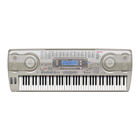
Casio WK-3700 Service Manual
Hide thumbs
Also See for WK-3700:
- User manual (132 pages) ,
- Midi implementation manual (80 pages) ,
- User manual (132 pages)
Advertisement
Advertisement
Table of Contents

Related Manuals for Casio WK-3700


Summary of Contents for Casio WK-3700
- Page 1 WK-3700 MAY. 2005 WK-3700 ELECTRONIC KEYBOARD INDEX...
-
Page 2: Table Of Contents
CONTENTS Specifications ---------------------------------------------------------------------------------------------- 1 Block Diagram --------------------------------------------------------------------------------------------- 3 Circuit Description --------------------------------------------------------------------------------------- 4 Printed Circuit Board ------------------------------------------------------------------------------------ 6 Disassembly ---------------------------------------------------------------------------------------------- 11 Diagnostic Program ------------------------------------------------------------------------------------ 17 Exploded View ------------------------------------------------------------------------------------------- 20 Parts List --------------------------------------------------------------------------------------------------- 21 Schematic Diagrams ----------------------------------------------------------------------------------- 25... -
Page 3: Specifications
Rhythm Patterns: 176 (internal, 16 user areas*) Tempo: Variable (226 steps, = 30 to 255) Chords: 3 fingering methods (CASIO CHORD, FINGERED, FULL RANGE CHORD) Rhythm Controller: START/STOP, INTRO/ENDING 1 and 2, VARIATION/FILL-IN 1 and 2, SYNCHRO/FILL-IN NEXT Accomp Volume:... - Page 4 SMF Player: Flash memory storage for up to 200 files* Supported Format: SMF0 Flash Memory Capacity: Shared Area: Approximately 3.5MB (waveform data, accompaniment data, SMF data) Further storage of waveform, accompaniment, and SMF data becomes impossible after the total of such data reaches approximately 3.5MB. Card Slot 3.3V SmartMedia (8MB, 16MB, 32MB, 64MB, 128MB)
-
Page 5: Block Diagram
BLOCK DIAGRAM SUB PCB (M734-MA3M) Phones/Output LCD Controller Assingnable Jack MIDI AC ADAPTOR ML9040-B02GA (IC401) DC 12V CONSOLE PCB LINE OUT (M734-CN3M) CONT DB0 ~ DB7 LCD PCB Speakers Q207 D209 (M734-LCD1M) D201 Power Amplifier Battery IC205 LA4636 Power Supply Circuit Q201 ~ Q205, Main IC201, D205... -
Page 6: Circuit Description
CIRCUIT DESCRIPTION KEY MATRIX F#11 G#11 A#11 F#12 G#12 A#12 C#21 D#21 F#21 C#22 D#22 F#22 G#21 A#21 C#31 G#22 A#22 C#32 D#31 F#31 G#31 A#31 D#32 F#32 G#32 A#32 C#41 D#41 F#41 C#42 D#42 F#42 G#41 A#41 C#51 G#42 A#42 C#52 D#51... -
Page 7: Button Matrix
BUTTON MATRIX FI10 LAYER SPLIT AUTO HARMONIZE – DEMO KEY LED MATRIX SWI0 SWI1 SWI2 SWI3 SWI4 SWI5 SWI6 SWI7 SYNCRO/ ACCOMP INTRO/ INTRO/ VARIATION/ VARIATION/ SWC0 TOUCH MODE FILL-IN VOLUME ENDING 1 ENDING 2 FILL-IN 1 FILL-IN 2 PRESET NEXT TEMPO START/... -
Page 8: Printed Circuit Board
PRINTED CIRCUIT BOARD MAIN PCB M737-MD1 Top View Bottom View — 6 —... - Page 9 SUB PCB M734-MA2M Top View SUB PCB M734-MA3M Top View — 7 —...
- Page 10 DISPLAY PCB M734-LCD1M Top View — 8 —...
- Page 11 CONSOLE PCB M734-CN1M CONSOLE PCB M734-CN2M CONSOLE PCB M734-CN4M CONSOLE PCB M734-CN5M CONSOLE PCB M734-CN7M CONSOLE PCB M734-CN3M CONSOLE PCB M734-CN6M — 9 —...
- Page 12 KEYBORD PCB JCM764T-KY1M KEYBORD PCB JCM764T-KY2M — 10 —...
-
Page 13: Disassembly
DISASSEMBLY 1. Remove the battery cover and then the battery. 2. Remove 36 screws and then the upper case. 3. Remove 4 screws, 8 speaker cords, 2 battery cords, 1cord (PM), 5 connectors (JD, JG2, JH, JK, JJ) and then the PCB ASS'Y (MA2M). Connectors Cord Connector... - Page 14 4. Remove 5 screws, 5 connectors (JA, JB, JD, JE, JF) and then the PCB ASS'Y (MA1M). Connectors Connectors Screws 5. Remove 8 screws, 1 connector and then the LCD ASS'Y (LCD1M). Screws Connector Screws Note: Tighten the screws in the order from 1 to 8 when reassembling.
- Page 15 6. Remove the volume knob, screws, connectors and then the CN1, CN2, CN3, CN4, CN5, CN6, CN7. Volume knob Screws Connector CN3M CN7M CN2M CN6M CN1M CN5M CN6M CN1M CN2M CN3M CN4M CN5M CN6M CN7M — 13 —...
- Page 16 7. Remove 2 screws and then the Bender assy. Screws 8. Remove 29 screws and then the lower case. Note: Tighten the screw with the arrow mark in the figure first when reassembling. — 14 —...
- Page 17 9. Remove 24 screws and then the PCB ASSY (KY1M, KY2M). 10.Remove the rubber keys. Projection Note: Pay attention to the positions of the rubber keys as one of them has a different length. Match the projections of the rubber keys with the holes of the lower case when reassembling. —...
- Page 18 11.Remove 27 screws and then the white keys. Note: Pay attention to the positions of the screw holes when reassembling. 12.Remove the black keys. — 16 —...
-
Page 19: Diagnostic Program
DIAGNOSTIC PROGRAM Initial Setup 1. Connect an AC adaptor. 2. Connect a Sustain pedal. 3. "Main" volume: MAX. NOTE: If there is no pedal or MIDI cable, pedal or MIDI check can be skipped. How to start diagnostic program 1. Press the “POWER” button while pressing the “Cursor key Up” and “Cursor key Down” buttons. 2. - Page 20 2. AC adaptor detection check. Message on LCD 1 Press “TONE” button. 1 ACJ ON 2 When the instrument detects that an AC adaptor is plugged in, an OK sound sounds. “ACJ OFF” appears and an NG sound sounds when the AC adaptor is not plugged (when batteries are used).
- Page 21 1 Press “TEMPO ” button. 1 LED CHK 2 LEDs illuminate in the following order. MODULATION FULL RANGE CHORD FINGERED CASIO CHORD DATA ACCESS DRAWBAR ORGAN 1 LED END 13. LCD check 1 Press “TEMPO ” button. 2 Turn on all segments of the LCD.
-
Page 22: Exploded View
EXPLODED VIEW 34 35 36 31-2 31-1 10-1 10-2 47-4 47-2 47-3 47-1 MA2M MA3M — 20 —... -
Page 23: Parts List
PARTS LIST WK-3700 Notes: This parts list does not include the cosmetic parts, which parts are marked with item No. "R-X" in the exploded view. Contact our spare parts department if you need these parts for refurbish. 1. Prices and specifications are subject to change without prior notice. - Page 24 Price Item Code No. Part Name Specification R Remarks Code Main PCB 10200670 PCB ASSY/MAIN TK-RJM505698*001 10164063 MEMORY CY62128DV30LL70ZAI 10195928 IC UPD63200GS-E1-A 10133600 MEMORY LP62S2048X-70LLT/Q 10197796 IC TA75S393F(TE85L.F) 10175415 IC R1151N001C-TR-FB 10197802 IC TC74VHCT08AFT(EL.K 10197809 IC TC7WH123FU(TE12L.F IC10 10197805 IC TC7SH00FU(TE85L.JF IC11,14 10197801 IC...
- Page 25 Price Item Code No. Part Name Specification R Remarks Code Console PCB CN1M~CN6M 10200672 PCB ASSY/CN1M TK-RJM502984*002 10123296 PCB ASSY/CN2M TK-RJM502985*001 10123297 PCB ASSY/CN3M TK-RJM502986*001 10123298 PCB ASSY/CN4M TK-RJM502987*001 10123299 PCB ASSY/CN5M TK-RJM502988*001 10123300 PCB ASSY/CN6M TK-RJM502989*001 69324293 LSI B CN1M IC301 UPD65881GK-062-9ET 10025037 TRANSISTOR...
- Page 26 Price Item Code No. Part Name Specification R Remarks Code Case Unit 10200667 COVER/BATTERY TK-M341288*003 10199200 PLATE/DISPLAY RJM502476-005V01 10197775 KNOB/ROTARY M341109-005 10130442 SPEAKER S12JA10A 10130441 SPEAKER S05JH54A 10197776 LCD TR4194N 10122917 PLATE/BACK LIGHT RJM502475-001V01 10122970 FILM RJM502473-001V01 10081190 PIECE/TOP RJM501982-001V01 10122965 CONNECTOR RJM502474-001V01 10200666 BENDER ASSY...
-
Page 27: Schematic Diagrams
SCHEMATIC DIAGRAMS MAIN PCB M737-MD1 — 25 —... - Page 28 SUB PCBs M734-MA2M/MA3M — 26 —...
- Page 29 DISPLAY PCB M734-LCD1M — 27 —...
- Page 30 CONSOLE PCB M734-CN1M — 28 —...
- Page 31 CONSOLE PCBs M734-CN2M/CN3M/CN4M/CN5M/CN6M/CN7M/CN8M/CN9M — 29 —...
- Page 32 KEYBORD PCBs JCM764T-KY1M/KY2M — 30 —...
- Page 33 CASIO COMPUTER CO.,LTD. Overseas Service Division 6-2, Hon-machi 1-Chome Shibuya-ku, Tokyo 151-8543, Japan...
Need help?
Do you have a question about the WK-3700 and is the answer not in the manual?
Questions and answers