
Related Manuals for A.W. Sperry Instruments DSA-2002P


Summary of Contents for A.W. Sperry Instruments DSA-2002P
- Page 1 11/05 FORM#275 OPERATING INSTRUCTIONS MODEL DSA-2002P DIGISNAP DIGIT DIGITAL AC SNAP-AROUND VOLT-OHM-AMMETER WITH PEAK HOLD...
-
Page 2: Table Of Contents
Contents 1.Safety Warnings ………………………………………………………1 2.Features ………………………………………………………………4 3.Specifications …………………………………………………………5 4.Instrument Layout ……………………………………………………7 5.Preparation for Measurement 5−1 Battery Voltage Check ………………………………………8 5−2 Checking Switch Setting and Operation ……………………8 6.Measurement 6−1 Current Measurement …………………………………………9 6−2 Voltage Measurement ………………………………………11 6−3 Resistance Measurement …………………………………… 12 7.Notes on Functions 7−1 Data Hold ………………………………………………………14 7−2 Sleep Function…………………………………………………... -
Page 3: 1.Safety Warnings
1.Safety Warnings ○ This instrument has been designed and tested according to IEC Publication 61010;Safety Requirements for Electronic Measuring Apparatus. This instruction manual contains warnings and safety rules which must be observed by the user to ensure safe operation of the instrument and retain it in safe condition. - Page 4 Following symbols are used on the instrument and in the instruction manual. Attention should be paid to each symbol to ensure your safety. Refer to the instructions in the manual. This symbol is marked where the user must refer to the instruction manual so as not to cause personal injury or instrument damage.
- Page 5 CAUTION ●Make sure that the function selector switch is set to an appropriate position before making measurement. ●Always make sure to insert the plug of each lead fully into the appropriate terminal on the instrument. ●Be sure to set the function selector switch to the "OFF" position after use.
-
Page 6: 2.Features
2.Features ●Tear-drop-shaped jaws for ease of use in crowded cable areas and other tight places. ●Provides a wide measuring range from 0 up to 2000A. ●Terminal cover to avoid the use of an incorrect terminal. ●Measures current variation as short as 10 msec with peak-hold feature. -
Page 7: 3.Specifications
3.Specifications ●Measuring Ranges and Accuracy(at 23±5℃, relative humidity 45-75%) ∼ ∼ AC Current 400A, 2000A Measuring Range Resolution Range Accuracy(Frequency Range) Maximum Measurement Time ±1.0%rdg±3dgt(50/60Hz) 0∼400.0A 0.1A 400A ±2.0%rdg±3dgt(40∼1kHz) Continuous 0∼1000A ±1.0%rdg±3dgt(50/60Hz) 1A 1000∼1500A 2000A ±3.0%rdg±3dgt(40∼1kHz) 15min 1500∼2000A ±3.0%rdg 5min (50/60Hz)... - Page 8 ●Operating System Dual Integration ●Display Liquid crystal display with a maximum count of 4000 ●Low Battery Warning "BATT" symbol is displayed on the digital display. ●Overrange Indication "OL" is displayed where input exceeds the upper limit of a range ●Response Time Approx.
-
Page 9: 4.Instrument Layout
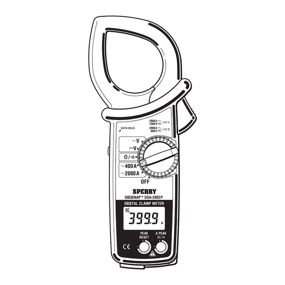
4.Instrument Layout Transformer Jaw Barrier Jaw Trigger Function Switch Data Hold Switch Display Reset Switch Mode Switch Drop Prevention Strap Terminal Cover OUTPUT Terminal ︸ COM Terminal Test Leads Mー7107 V/Ω Terminal Recorder Output Plug Mー8102 ● LCD INDICATOR DC Current AC Current Data Hold Mode Resistance... -
Page 10: 5.Preparation For Measurement
5.Preparation for Measurement 5−1 Checking Battery Voltage ①Set the function selector switch to any position other than "OFF". ②When the display is clear without "BATT" showing, proceed to measurement. ③When the display blanks or "BATT" is indicated, replace the batteries according to section 8: battery replacement. NOTE ●... -
Page 11: 6.Measurement
6.Measurement 6−1 Current Measurement WARNING ●Do not make measurement on a circuit above 750V AC. This may cause shock hazard or damage to the instrument or equipment under test. ● Transformer jaw tips are designed not to short the circuit under test. - Page 12 ③Take the reading on the display. NOTE ● During current measurement, keep the transformer jaws fully closed. Otherwise, accurate measurement cannot be made. The maximum measurable conductor size is 54.5mm in diameter. ● When measuring a larger current, the transformer jaws may buzz. This is not a fault and does not affect the accuracy at all.
-
Page 13: 6−2 Voltage Measurement
6−2 Voltage Measurement WARNING ●Do not make measurement on a circuit above 750V AC or 1000V DC. This may cause shock hazard or damage to the instrument or equipment under test. ●Do not make measurement with the battery compartment cover removed. ●Keep your fingers and hands behind the barrier during measurement. -
Page 14: 6−3 Resistance Measurement
6−3 Resistance Measurement WARNING ●Before attempting to make measurement, make sure that the circuit under test is not live. The instrument is protected against a voltage up to 600V. ●Do not make measurement with the battery compartment cover removed. ●Keep your fingers and hands behind the barrier during measurement. 6−3−1 Resistance Measurement (Normal Mode) ①Set the function selector switch to the "Ω/ "... -
Page 15: Continuity Check
6−3−2 Continuity Check ①Set the function selector switch to the "Ω/ " position. ②Slide the terminal cover to the left. Plug the red test lead into the V/Ω terminal and the black test lead into the COM terminal. ③Press the mode button to set the instrument to the continuity check mode. -
Page 16: 7.Notes On Functions 7−1 Data Hold
7.Notes on Functions 7−1 Data Hold This is a function used to freeze the measured value on the display. ①Press the data hold button. The reading becomes frozen and the "H" symbol is shown on the display, indicating the instrument in the data hold mode. -
Page 17: 7−3 Output For Recorder
②To enable the sleep function, turn the function selector switch back to "OFF", then to any other position. NOTE ● The instrument consumes small amount of current in the sleep mode. When the instrument is not in use, make sure to set the function selector switch to "OFF". -
Page 18: 7−4 Mode Switching Function
[How to attach a pair of leads to the recorder output plug] Attach one end of the leads to the recorder output plug observing correct polarity, then connect the other end to the recorder. DANGER Never apply voltage to the output terminal. 7−4 Mode Switching Function On a AC current ("∼400A"... -
Page 19: 8.Battery Replacement
8.Battery Replacement WARNING ●To avoid electric shock hazard, make sure to set the function selector switch to "OFF" and remove the test leads from the instrument before trying to replace batteries. CAUTION ●Do not mix new and old batteries. ●Make sure to install batteries in correct polarity as indicated in the battery compartment. - Page 20 MEMO ― 18 ―...
- Page 21 MEMO ― 19 ―...
- Page 22 MEMO ― 20 ―...
- Page 23 Lifetime Limited Warranty The attention to detail of this fine snap-around instrument is further enhanced by the application of A.W. Sperry s unmatched service and concern for detail and reliability. These A.W. Sperry snap-arounds are internationally accepted by craftsmen and servicemen for their unmatched performance.
Need help?
Do you have a question about the DSA-2002P and is the answer not in the manual?
Questions and answers