Table of Contents
Advertisement
Available languages
Available languages
OPERATOR'S MANUAL
MANUAL DEL OPERADOR
5,000 WATT GENERATOR
Generador de 5000 watts
HU5000 Series
Serie HU5000
To register your HUSky product,
please visit:
http://register.huskyoutdoortools.com/
Para registrar su producto de HUSky,
por favor visita:
http://register.huskyoutdoortools.com/
Your generator has been engineered and manufactured to our high standard for dependability, ease of operation, and
operator safety. When properly cared for, it will give you years of rugged, trouble-free performance.
DANGER:
You WILL be KILLED or SERIOUSLY HURT if you do not follow the instructions in this operator's
manual.
Thank you for your purchase.
SAVE THIS MANUAL FOR FUTURE REFERENCE
Su nuevo generador ha sido diseñado y fabricado de conformidad con estrictas normas para brindar fiabilidad, facilidad de
uso y seguridad para el operador. Con el debido cuidado, le brindará muchos años de sólido y eficiente funcionamiento.
PELIGRO:
El incumplimiento de las instrucciones en este manual del operador puede CAUSARLE LA MUERTE
O LESIONARLE GRAVEMENTE.
Le agradecemos su compra.
GUARDE ESTE MANUAL PARA FUTURAS CONSULTAS
NEUTRAL FLOATING
PUNTO NEUTRO FLOTANTE
Advertisement
Chapters
Table of Contents

Related Manuals for Husky HU5000 Series


Summary of Contents for Husky HU5000 Series
- Page 1 HU5000 Series Serie HU5000 To register your HUSky product, please visit: http://register.huskyoutdoortools.com/ Para registrar su producto de HUSky, por favor visita: http://register.huskyoutdoortools.com/ NEUTRAL FLOATING PUNTO NEUTRO FLOTANTE Your generator has been engineered and manufactured to our high standard for dependability, ease of operation, and operator safety.
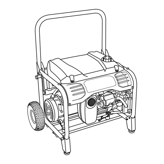
- Page 2 See this fold-out section for all of the figures referenced in the operator’s manual. Consulte esta sección desplegable para ver todas las figuras a las que se hace referencia en el manual del operador.
- Page 3 Fig. 1 Fig. 4 A - Bolt (perno) B - Frame (armazón) C - Frame support with foot (soporte del armazón con pie) D - Flat washer (arandela plana) E - Lock washer (arandela de seguridad) F - Nut (tuerca) Fig.
- Page 4 Fig. 7 Fig. 10 Fig. 13 A - Oil cap/dipstick (tapa de relleno de aceite/ A - Fuel valve (válvula de combustible) varilla medidora de aceite) B - Off (apagado) B - Oil fill hole (agujero de llenado de aceite) C - On (encendido) Fig.
- Page 5 Fig. 16 Fig. 17 A - Carburetor drain screw (tornillo de drenaje del carburador) Fig. 18 A - Fuel line (conducto de combustible) B - Fuel valve (válvula de combustible) C - Petcock (llave de purga) D - Off (apagado) A - Fuel line (conducto de combustible) E - On (encendido) B - Fuel filter (filtro de combustible)
-
Page 6: Table Of Contents
TABLE OF CONTENTS Introduction ..................................2 Important Safety Instructions .............................3-4 Specific Safety Rules ..............................4 Symbols ..................................5-7 Electrical ..................................7-9 Features ..................................10 Assembly ................................11-12 Operation ................................12-13 Maintenance ................................14-16 Troubleshooting ................................17 ... -
Page 7: Important Safety Instructions
IMPORTANT SAFETy INSTRUCTIONS Never start or run the engine inside a closed or partially enclosed area. Breathing exhaust fumes will kill you. DANGER: Always wear eye protection with side shields marked to Carbon Monoxide. Using a generator indoors WILL KILL comply with ANSI Z87.1 as well as hearing protection YOU IN MINUTES. -
Page 8: Specific Safety Rules
IMPORTANT SAFETy INSTRUCTIONS Use only authorized replacement parts and accessories Maintain the unit per maintenance instructions in this and follow instructions in the Maintenance section of this Operator’s Manual. manual. Use of unauthorized parts or failure to follow ... -
Page 9: Symbols
SyMBOLS The following signal words and meanings are intended to explain the levels of risk associated with this product. SyMBOL SIGNAL MEANING Indicates an imminently hazardous situation, which, if not avoided, will result DANGER: in death or serious injury. Indicates a potentially hazardous situation, which, if not avoided, could result WARNING: in death or serious injury. -
Page 10: Safety Labels
SyMBOLS Some of the following symbols may be used on this product. Please study them and learn their meaning. Proper interpretation of these symbols will allow you to operate the product better and safer. SyMBOL NAME DESIGNATION/EXPLANATION Volts Voltage Amperes Current Hertz Frequency (cycles per second) -
Page 11: Electrical
SyMBOLS FUEL WARNING No smoking when filling with gasoline. Do not overfill. Full level is 1 in. below the top of the fuel neck. Stop the engine for five minutes before refueling to avoid the heat from the muffler igniting fuel vapors. ENGINE LUBRICANT WARNING You must add lubricant before first op- erating the generator. - Page 12 ELECTRICAL ELECTRIC MOTOR LOADS It is characteristic of common electric motors in normal operation to draw up to six times their running current while start- ing. This table may be used to estimate the watts required to start “Code G” electric motors; however, if an electric motor fails to start or reach running speed, turn off the appliance or tool immediately to avoid equipment damage.
- Page 13 ELECTRICAL POWER MANAGEMENT Estimated Estimated To prolong the life of the generator and attached devices, Application/Equipment Starting Run Watts it is important to take care when adding electrical loads to Watts the generator. There should be nothing connected to the Emergency / Home Standby generator outlets before starting its engine.
-
Page 14: Features
FEATURES PRODUCT SPECIFICATIONS GENERATOR ENGINE Engine Type ......4 Stroke, OHC (Chain Drive) Rated Voltage .............120V/240V Rated Amps ............. 41.6A/20.8A Bore x Stroke ..........75 mm x 65 mm Rated Output ............5,000 W Cooling System ...........Forced Air Starting Watts ............6,250 W Compression Ratio ............ -
Page 15: Assembly
ASSEMBLy LOOSE PARTS LIST WARNING: See Figure 2. If any parts are damaged or missing do not operate The following items are included with the generator: this product until the parts are replaced. Use of this product with damaged or missing parts could result in Description Qty. -
Page 16: Operation
ASSEMBLy NOTE: The hitch pin should be pushed into the axle until the center of the pin rests on top of the axle. WARNING: Repeat with the second wheel. Do not attempt to lift the unit by the handle assembly. If it is necessary to lift the generator, always grasp by SECURING THE HANDLE the frame. - Page 17 OPERATION NOTE: Non-detergent or 2-stroke engine lubricants will OXyGENATED FUELS damage the engine and should not be used. DO NOT USE E85 FUEL. IT WILL VOID yOUR WAR- Unscrew the oil cap/dipstick and remove. RANTy. Wipe dipstick clean and re-seat in hole; do not re- NOTE: Fuel system damage or performance problems re- thread.
-
Page 18: Maintenance
CHANGING ENGINE LUBRICANT WARNING: See Figure 13. When servicing, use only identical Husky replacement Remove the oil cap/dipstick. parts. Use of any other parts may create a hazard or Place a container underneath the oil drainage bolt to cause product damage. - Page 19 Occasionally the fuel filter may become clogged and need Inspect the spark arrestor for breaks or holes. Replace replacing. To purchase a replacement fuel filter contact Husky if necessary. To purchase a replacement spark arrestor customer service at 1-866-340-3912.
-
Page 20: Maintenance
MAINTENANCE STORAGE When preparing the generator for storage, allow the unit to cool completely then follow the guidelines below. STORAGE TIME PRIOR TO STORING Less than 2 months Drain gasoline from tank and dispose of in a suitable container according to state and local ordinances. -
Page 21: Troubleshooting
TROUBLESHOOTING PROBLEM POSSIBLE CAUSE SOLUTION Engine will not start. Engine switch is OFF. Turn engine switch to ON. No fuel. Fill fuel tank. Lubricant level is low. Check engine lubricant level and fill, if necessary. Fuel valve is OFF. Turn fuel valve ON. Spark plug faulty, fouled, or improperly Replace spark plug. -
Page 22: Warranty
LIMITED WARRANTy WARRANTy COVERAGE Techtronic Industries North America, Inc., (the Company) warrants to the original retail purchaser that this Husky Product is free from defects in material and workmanship and agrees to repair or replace, at the Company’s sole discretion, any defective Product free of charge within these time periods from the date of purchase: ... -
Page 23: Warranty
WARRANTy LIMITED 3 yEAR ENGINE WARRANTy Limited Manufacturer’s Warranty from Subaru Robin (Effective with engines purchased from Robin America, Wood Dale, IL, after April 1, 2008) Robin America, Inc., a division of Fuji Heavy Industries, Ltd. (herein “Subaru Robin”), warrants that each new engine sold by it will be free, under normal use and service, from defects in material and workmanship for a period listed below from the date of sale to the original retail purchaser. - Page 24 NOTES 22 - English...
- Page 25 NOTES 22 - English...
- Page 26 ÍndiCe de Contenido Introducción ................................... 2 Instrucciones de seguridad importantes ........................3-4 Reglas de seguridad específicas ........................... 4 Símbolos ..................................5-7 Aspectos eléctricos ..............................7-9 Características ................................10 Armado ...................................11-12 Funcionamiento ..............................12-13 Mantenimiento ................................14-16 ...
-
Page 27: Instrucciones De Seguridad Importantes
inStrUCCioneS de SegUridad iMportanteS Siempre utilice protección ocular con protección lateral con la marca de cumplimiento de la norma ANSI Z87.1, como así peligro: también protección auditiva cuando utilice este equipo. Monóxido de carbono. Usar un generador en el interior LO Mantenga a todos los circunstantes, niños y animales por lo MATARÁ... -
Page 28: Reglas De Seguridad Específicas
inStrUCCioneS de SegUridad iMportanteS manera, los componentes del generador pueden recalentarse de las instrucciones de mantenimiento puede significar un riesgo o exigirse demasiado, lo que podría producir una falla en el de descarga eléctrica o de lesiones. generador. Mantenga la unidad según las instrucciones de mantenimiento Use únicamente repuestos y accesorios autorizados y siga las señaladas en este manual del operador. -
Page 29: Símbolos
SÍMBoloS Las siguientes palabras de señalización y sus significados tienen el objeto de explicar los niveles de riesgo relacionados con este producto. SÍMBolo SeÑal SigniFiCado Indica una situación peligrosa inminente, la cual, si no se evita, causará peligro: lesiones graves o mortales. Indica una situación peligrosa posible, la cual, si no se evita, podría causar adVertenCia: lesiones graves o mortales. - Page 30 SÍMBoloS Es posible que se empleen en este producto algunos de los siguientes símbolos. Le suplicamos estudiarlos y aprender su significado. Una correcta interpretación de estos símbolos le permitirá utilizar mejor y de manera más segura el producto. SÍMBolo noMBre denoMinaCión / expliCaCión Voltios Voltaje...
-
Page 31: Aspectos Eléctricos
SÍMBoloS adVertenCia de CoMBUStiBle No fume al abastecer el combustible. No llene de más. El nivel de lleno es 25 mm (1 pulg.) debajo del cuello del tanque de combustible. Pare la marcha del motor cinco minutos antes del reabastecimiento de combustible para evitar que el calor del silenciador encienda los vapores de combustible. - Page 32 aSpeCtoS eléCtriCoS CargaS de MotoreS eléCtriCoS Es característico en el funcionamiento normal de los motores eléctricos comunes consumir durante el arranque hasta seis veces su corriente de operación. Esta tabla puede emplearse para estimar la potencia necesaria (en vatios) para arrancar los motores eléctricos de “Código G”;...
- Page 33 aSpeCtoS eléCtriCoS adMiniStraCión de la potenCia estimado en marcha A fin de prolongar la vida útil del generador y los dispositivos Herramienta o aparato W de en vatios acoplados, es importante tener cuidado al agregar cargas arranque eléctricas al generador. NO debe haber equipo alguno emergencia / en casa espera conectado a los tomacorrientes del generador antes de poner en marcha el motor respectivo.
-
Page 34: Características
CaraCterÍStiCaS eSpeCiFiCaCioneS del prodUCto Motor generador Voltaje nominal ..........120 V / 240 V Tipo de motor ..........4 tiempos, OHC (cadena de accionamiento) Amperaje nominal..........41,6A/20,8A Diámetro interior x Carrera ......75 mm x 65 mm Salida nominal ............5000 W Sistema de enfriamiento........Aire forzado Salida máxima ............6250 W Frecuencia nominal ............60 Hz... -
Page 35: Armado
arMado liSta de piezaS SUeltaS adVertenCia: Voir la Figure 2. Si hay piezas dañadas o faltantes, no utilice este Los siguientes accesorios vienen incluidos con el producto sin haber reemplazado todas las piezas. La generador: inobservancia de esta advertencia podría causar lesiones núm. -
Page 36: Funcionamiento
arMado nota: Debe introducirse el pasador de enganche en el Para plegar el mango a fin de almacenar la unidad, mantenga eje hasta que el centro de aquél descanse en la parte presionado el pasador de liberación mientras empuja el superior de éste. - Page 37 FUnCionaMiento nota: El lubricante sin detergente o para motor de dos CoMBUStiBleS oxigenadoS tiempos daña el motor, por lo cual no debe usarse. n o u s e c o m b u s t i b l e e 8 5 . a n u l a r á s u Desenrosque la tapa de relleno de aceite/varilla medidora garantÍa.
-
Page 38: Mantenimiento
Vea la figura 13. Al dar servicio a la unidad, sólo utilice piezas de repuesto Retire la tapa de relleno de aceite/varilla medidora de Husky idénticas. El empleo de piezas diferentes puede aceite. causar un peligro o dañar el producto. - Page 39 Centro de asistencia al de Husky al 1-866-340-3912. cliente de Husky llamando al 1-866-340-3912. nota: El tanque de combustible debe estar vacío antes de Utilice un cepillo para retirar los depósitos de carbono reemplazar el filtro.
- Page 40 ManteniMiento alMaCenaMiento Al preparar el generador para guardarlo, deje que la unidad se enfríe por completo y luego siga los lineamientos señalados abajo. tieMpo de anteS de gUardarlo alMaCenaMiento Menos de dos meses Vacíe el tanque de combustible y colóquelo en un recipiente apropiado según lo establecido por las disposiciones estatales y locales.
-
Page 41: Corrección De Problemas
CorreCCión de proBleMaS proBleMa CaUSa poSiBle SolUCión El motor no arranca. El interruptor del motor está en Ponga el interruptor del motor en apagado (OFF). encendido (ON). No hay combustible. Llene el tanque de combustible. Está bajo el nivel de lubricante. Revise el nivel del lubricante del motor, y reabastézcalo si es necesario. -
Page 42: Garantía
Techtronic Industries North America, Inc., (la Compañía) garantiza al comprador minorista original que este Producto Husky carece de defectos en material y mano de obra, y acuerda reparar o reemplazar, a la entera discreción de la Compañía, cualquier Producto defectuoso sin cargo en los siguientes períodos a partir de la fecha de la compra: Tres años si el Producto se utiliza exclusivamente para fines personales, familiares o domésticos. - Page 43 garantÍa Motor Con garantÍa liMitada de 3 aÑoS garantía limitada del fabricante proporcionada por Subaru robin (Válida para los motores adquiridos en Robin America, Wood Dale, IL, luego del 1 de Abril de 2008) Robin America, Inc., una subsidiaria de Fuji Heavy Industries, Ltd. (en adelante denominada “Subaru Robin”), garantiza al comprador minorista original que cada motor nuevo que se venda carecerá...
- Page 44 5,000 WATT GENERATOR Generador de 5000 watts HU5000 Series OPERATOR’S MANUAL Serie HU5000 MANUAL DEL OPERADOR WARNING: SERVICE For parts or service, contact your nearest authorized service dealer. Be sure The engine exhaust from this product to provide all relevant information when you call or visit. For the location of the contains chemicals known to the authorized service dealer nearest you, please call 1-866-340-3912.
Need help?
Do you have a question about the HU5000 Series and is the answer not in the manual?
Questions and answers
where can I get a carburetor repair kit
carburetor repair kit