ASROCK G41M-S3 User Manual
Hide thumbs
Also See for G41M-S3:
- User manual (50 pages) ,
- Specifications (5 pages) ,
- Installation manual (136 pages)
Table of Contents
Advertisement
Quick Links
Download this manual
See also:
Installation Manual
ASRock G41M-S3 Manual(1)(1)
http://www.manuallib.com/file/2586536
From ManualLib.com
ManualLib.com collects and classifies the global product
instrunction manuals to help users access anytime and
anywhere, helping users make better use of products.
Home: http://www.manuallib.com/ Chinese: http://www.shuomingshuku.com/
This Manual: http://www.manuallib.com/file/2586536
Advertisement
Table of Contents

Related Manuals for ASROCK G41M-S3


Summary of Contents for ASROCK G41M-S3
- Page 1 ASRock G41M-S3 Manual(1)(1) http://www.manuallib.com/file/2586536 From ManualLib.com ManualLib.com collects and classifies the global product instrunction manuals to help users access anytime and anywhere, helping users make better use of products. Home: http://www.manuallib.com/ Chinese: http://www.shuomingshuku.com/ This Manual: http://www.manuallib.com/file/2586536...
-
Page 2: User Manual
G41M-S3 User Manual Version 1.0 Published October 2009 Copyright©2009 ASRock INC. All rights reserved. 1 1 1 1 1 This Manual: http://www.manuallib.com/file/2586536... - Page 3 (including damages for loss of profits, loss of business, loss of data, interruption of business and the like), even if ASRock has been advised of the possibility of such damages arising from any defect or error in the manual or product.
-
Page 4: Table Of Contents
Contents Contents Contents Contents Contents 1 Introduction 1 Introduction 1 Introduction ........... 1 Introduction 1 Introduction ................................. 5 5 5 5 5 ........... 1.1 Package Contents ............5 1.2 Specifications ..............6 1.3 Motherboard Layout ............10 1.4 I/O Panel ................. 11 2 Installation 2 Installation ............. - Page 5 4 Software Support 4 Software Support 4 Software Support .................................... 50 4 Software Support 4 Software Support ........... 4.1 Install Operating System ..........50 4.2 Support CD Information ..........50 4.2.1 Running Support CD ..........50 4.2.2 Drivers Menu ............50 4.2.3 Utilities Menu ............
-
Page 6: Introduction
In case any modifications of this manual occur, the updated version will be available on ASRock website without further notice. You may find the latest VGA cards and CPU support lists on ASRock website as well. ASRock website http://www.asrock.com If you require technical support related to this motherboard, please visit our website for specific information about the model you are using. -
Page 7: Specifications
1 . 2 1 . 2 1 . 2 1 . 2 1 . 2 Specifications Specifications Specifications Specifications Specifications - Micro ATX Form Factor: 9.6-in x 7.6-in, 24.4 cm x 19.3 cm Platform - LGA 775 for Intel Core 2 Extreme / Core 2 Quad / Core ®... - Page 8 ® ® / XP 64-bit compliant - FCC, CE Certifications - EuP Ready (EuP ready power supply is required) (see CAUTION 16) * For detailed product information, please visit our website: http://www.asrock.com 7 7 7 7 7 This Manual: http://www.manuallib.com/file/2586536...
- Page 9 WARNING Please realize that there is a certain risk involved with overclocking, including adjusting the setting in the BIOS, applying Untied Overclocking Technology, or using the third- party overclocking tools. Overclocking may affect your system stability, or even cause damage to the components and devices of your system. It should be done at your own risk and expense.
- Page 10 10. It is a user-friendly ASRock overclocking tool which allows you to surveil your system by hardware monitor function and overclock your hardware devices to get the best system performance under Windows environment. ® Please visit our website for the operation procedures of ASRock OC Tuner.
-
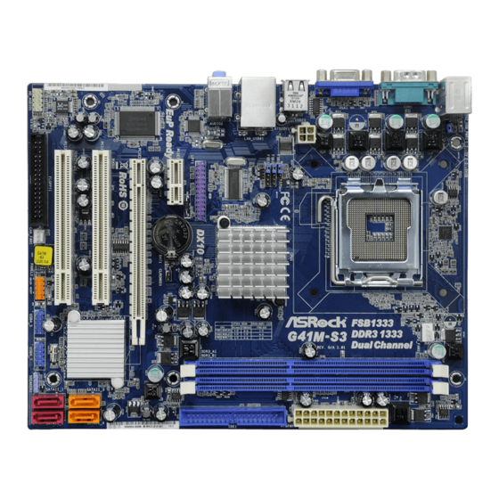
Page 11: Motherboard Layout
1.3 Motherboard Layout 1.3 Motherboard Layout 1.3 Motherboard Layout 1.3 Motherboard Layout 1.3 Motherboard Layout 19.3cm (7.6 in) PS2_USB_PWR1 CPU_FAN1 USB 2.0 T: USB2 B: USB3 FSB1 FSB2 FSB3 Intel USB 2.0 Top: T: USB0 RJ-45 B: USB1 Chipset LPT1 DX10 IDE1 CMOS... -
Page 12: I/O Panel
1.4 I/O P 1.4 I/O P 1.4 I/O P 1.4 I/O P 1.4 I/O Panel anel anel anel anel PS/2 Mouse Port (Green) Microphone (Pink) USB 2.0 Ports (USB23) USB 2.0 Ports (USB01) RJ-45 Port VGA Port Line In (Light Blue) COM Port Line Out (Lime) PS/2 Keyboard Port (Purple) -
Page 13: Installation
Chapter 2 Installation Chapter 2 Installation G41M-S3 is a Micro ATX form factor (9.6" x 7.6", 24.4 x 19.3 cm) motherboard. Before you install the motherboard, study the configuration of your chassis to ensure that the motherboard fits into it. -
Page 14: Cpu Installation
2.3 CPU Installation 2.3 CPU Installation 2.3 CPU Installation 2.3 CPU Installation 2.3 CPU Installation For the installation of Intel 775-LAND CPU, please follow the steps below. 775-Pin Socket Overview Before you insert the 775-LAND CPU into the socket, please check if the CPU surface is unclean or if there is any bent pin on the socket. - Page 15 For proper inserting, please ensure to match the two orientation key notches of the CPU with the two alignment keys of the socket. Step 2-3. Carefully place the CPU into the socket by using a purely vertical motion. Step 2-4. Verify that the CPU is within the socket and properly mated to the orient keys.
-
Page 16: Installation Of Heatsink And Cpu Fan
Installation of CPU Fan and Heatsink Installation of CPU Fan and Heatsink Installation of CPU Fan and Heatsink Installation of CPU Fan and Heatsink Installation of CPU Fan and Heatsink This motherboard is equipped with 775-Pin socket that supports Intel 775-LAND CPU. Please adopt the type of heatsink and cooling fan compliant with Intel 775-LAND CPU to dissipate heat. -
Page 17: Installation Of Memory Modules (Dimm)
2.5 Installation of Memory Modules (DIMM) 2.5 Installation of Memory Modules (DIMM) G41M-S3 motherboard provides two 240-pin DDR3 (Double Data Rate 3) DIMM slots, and supports Dual Channel Memory Technology. For dual channel configuration, you always need to install two identical (the same brand, speed, size and chip-type) memory modules in the DDR3 DIMM slots to activate Dual Channel Memory Technology. -
Page 18: Expansion Slots (Pci And Pci Express Slots)
2.6 Expansion Slots (PCI and PCI Express Slots) 2.6 Expansion Slots (PCI and PCI Express Slots) 2.6 Expansion Slots (PCI and PCI Express Slots) 2.6 Expansion Slots (PCI and PCI Express Slots) 2.6 Expansion Slots (PCI and PCI Express Slots) There are 2 PCI slots and 2 PCI Express slots on this motherboard. -
Page 19: Jumpers Setup
2.7 Jumpers Setup 2.7 Jumpers Setup 2.7 Jumpers Setup 2.7 Jumpers Setup 2.7 Jumpers Setup The illustration shows how jumpers are setup. When the jumper cap is placed on pins, the jumper is “Short”. If no jumper cap is placed on pins, the jumper is “Open”. The illustration shows a 3-pin jumper whose pin1 and pin2 are “Short”... -
Page 20: Fsb1/Fsb2/Fsb3 Jumper
FSB1 / FSB2 / FSB3 Jumper (FSB1, 3-pin jumper, see p.10 No. 26) FSB1 (FSB2, 5-pin jumper, see p.10 No. 26) FSB2 Default (FSB3, 5-pin jumper, see p.10 No. 26) FSB3 Standard Setting: If you adopt below DRAM / CPU configuration on this motherboard, you need to adjust the jumpers. -
Page 21: Onboard Headers And Connectors
2.8 Onboard Headers and Connectors 2.8 Onboard Headers and Connectors 2.8 Onboard Headers and Connectors 2.8 Onboard Headers and Connectors 2.8 Onboard Headers and Connectors Onboard headers and connectors are NOT jumpers. Do NOT place jumper caps over these headers and connectors. Placing jumper caps over the headers and connectors will cause permanent damage of the motherboard! FDD connector... - Page 22 USB 2.0 Headers Besides four default USB 2.0 USB_PWR ports on the I/O panel, there are (9-pin USB6_7) DUMMY two USB 2.0 headers on this (see p.10 No. 15) motherboard. Each USB 2.0 header can support two USB USB_PWR 2.0 ports. USB_PWR (9-pin USB4_5) (see p.10 No.
- Page 23 “Disable front panel jack detection”, and save the change by clicking “OK”. For Windows 7 / 7 64-bit / Vista / Vista 64-bit OS: ® Click the right-top “Folder” icon , choose “Disable front panel jack detection”, and save the change by clicking “OK”. G.
- Page 24 ATX Power Connector Please connect an ATX power supply to this connector. (24-pin ATXPWR1) (see p.10 No. 6) Though this motherboard provides 24-pin ATX power connector, it can still work if you adopt a traditional 20-pin ATX power supply. To use the 20-pin ATX power supply, please plug your power supply along with Pin 1 and Pin 13.
-
Page 25: Sataii Hard Disk Setup Guide
2 . 9 2 . 9 2 . 9 SAT T T T T AII Hard Disk Setup Guide AII Hard Disk Setup Guide AII Hard Disk Setup Guide AII Hard Disk Setup Guide 2 . 9 2 . 9 AII Hard Disk Setup Guide Before installing SATAII hard disk to your computer, please carefully read below SATAII hard disk setup guide. -
Page 26: Installation
2 . 1 0 2 . 1 0 2 . 1 0 2 . 1 0 2 . 1 0 Serial A Serial A Serial A Serial A Serial AT T T T T A (SA A (SA A (SA A (SAT T T T T A) / Serial A A (SA A) / Serial A... -
Page 27: Bios Setup Utility
Chapter 3 BIOS SETUP UTILITY Chapter 3 BIOS SETUP UTILITY Chapter 3 BIOS SETUP UTILITY Chapter 3 BIOS SETUP UTILITY Chapter 3 BIOS SETUP UTILITY 3.1 Introduction 3.1 Introduction 3.1 Introduction 3.1 Introduction 3.1 Introduction This section explains how to use the BIOS SETUP UTILITY to configure your system. The SPI Memory on the motherboard stores the BIOS SETUP UTILITY. -
Page 28: Navigation Keys
System Date [Fri 10/16/2009] Use [+] or [-] to configure system Time. BIOS Version : G41M-S3 P1.00 Processor Type : Intel (R) Core (TM) 2 Duo CPU E6850 @ 3.00GHz (64bit) Processor Speed : 3148MHz Microcode Update... -
Page 29: Oc Tweaker Screen
3.3 OC T OC T OC T OC T OC Tweak weak weak weak weaker Screen er Screen er Screen er Screen er Screen In the OC Tweaker screen, you can set up overclocking features. BIOS SETUP UTILITY Main OC Tweaker Advanced H/W Monitor Boot... - Page 30 DRAM Timing Configuration BIOS SETUP UTILITY OC Tweaker DRAM Timing Control DRAM tCL Value [Auto] DRAM tCL DRAM tRCD [Auto] Min = 5 DRAM tRP [Auto] Max = 10 DRAM tRAS [Auto] DRAM tRFC [Auto] DRAM tWR [Auto] DRAM tWTR [Auto] DRAM tRRD [Auto]...
- Page 31 Ratio Status This is a read-only item, which displays whether the ratio status of this motherboard is “Locked” or “Unlocked”. If it shows “Unlocked”, you will find an item Ratio CMOS Setting appears to allow you changing the ratio value of this motherboard. Ratio CMOS Setting If the ratio status is unlocked, you will find this item appear to allow you changing the ratio value of this motherboard.
-
Page 32: Advanced Screen
Enter Go to Sub Screen General Help BIOS Update Utility Load Defaults Save and Exit ASRock Instant Flash Exit v02.54 (C) Copyright 1985-2005, American Megatrends, Inc. Setting wrong values in this section may cause the system to malfunction. This Manual: http://www.manuallib.com/file/2586536... -
Page 33: Cpu Configuration
3.4.1 3.4.1 CPU Configuration CPU Configuration 3.4.1 3.4.1 3.4.1 CPU Configuration CPU Configuration CPU Configuration BIOS SETUP UTILITY Advanced CPU Configuration This should be enabled in order to enable or Overclock Mode [Auto] disable the “Enhanced CPU Frequency (MHz) [200] Halt State”. - Page 34 Intel (R) Virtualization tech. When this option is set to [Enabled], a VMM (Virtual Machine Architecture) can utilize the additional hardware capabilities provided by Vanderpool Technology. This option will be hidden if the installed CPU does not support Intel (R) Virtualization Technology. CPU Thermal Throttling You may select [Enabled] to enable P4 CPU internal thermal control mecha- nism to keep the CPU from overheated.
-
Page 35: Chipset Configuration
3.4.2 3.4.2 3.4.2 Chipset Configuration Chipset Configuration Chipset Configuration Chipset Configuration 3.4.2 3.4.2 Chipset Configuration BIOS SETUP UTILITY Advanced Chipset Settings DRAM RCOMP and tRD Configuration DRAM DLL SKEW Configuration Fixed Mode Operation [Enabled] Intelligent Energy Saver [Disabled] Primary Graphics Adapter [PCI] Shared Memory [Auto]... - Page 36 DRAM CH0 G3 (Control2) This controls the number of DRAM CH0 G3 (Control2). Min: 1. Max: 15. The default value is [Auto]. DRAM CH0 G4 (Clocks1) This controls the number of DRAM CH0 G4 (Clocks1). Min: 1. Max: 15. The default value is [Auto].
- Page 37 DRAM DLL SKEW Configuration BIOS SETUP UTILITY Advanced DRAM DLL SKEW Settings DRAM CH0 CLKSET0 SKEW Info:0-0-0-0-0-0 [Auto] DRAM CH0 CLKSET0 SKEW DRAM CH0 CLKSET1 SKEW Info:0-0-0-0-0-0 [Auto] DRAM CH0 CLKSET1 SKEW DRAM CH0 CMD SKEW Info :0-0-0-0-0-0-0 [Auto] DRAM CH0 CMD SKEW DRAM CH0 CTRL0 SKEW Info :0-0-0-0-0-0-0 [Auto]...
- Page 38 DRAM CH1 CMD SKEW This controls the number of DRAM CH1 CMD SKEW. The default value is [Auto]. DRAM CH1 CTRL0 SKEW This controls the number of DRAM CH1 CTRL0 SKEW. The default value is [Auto]. DRAM CH1 CTRL1 SKEW This controls the number of DRAM CH1 CTRL1 SKEW.
- Page 39 Flex Mode Operation This allows you to enable or disable flex mode operation feature. The default value is [Enabled]. Configuration options: [Enabled] and [Disabled]. Intelligent Energy Saver Intelligent Energy Saver is a revolutionary technology that delivers unparalleled power savings. The default value is [Disabled]. Configuration options: [Enabled] and [Disabled].
- Page 40 OnBoard Lan This allows you to enable or disable the “OnBoard Lan” feature. This Manual: http://www.manuallib.com/file/2586536...
-
Page 41: Acpi Configuration
3.4.3 3.4.3 3.4.3 3.4.3 3.4.3 ACPI Configuration ACPI Configuration ACPI Configuration ACPI Configuration ACPI Configuration BIOS SETUP UTILITY Advanced ACPI Configuration Select auto-detect or disable the STR feature. Suspend To RAM [Disabled] [Power Off] Restore on AC/Power Loss [Disabled] Ring-In Power On [Disabled] PCI Devices Power On [Disabled]... -
Page 42: Storage Configuration
3.4.4 3.4.4 Storage Configuration Storage Configuration 3.4.4 3.4.4 Storage Configuration 3.4.4 Storage Configuration Storage Configuration BIOS SETUP UTILITY Advanced Set [Compatible] Storage Configuration when Legacy OS (MS-DOS, Win NT) ATA/IDE Configuration [Enhanced] device is used. Set [Enhanced] SATAII_1 [Hard Disk] when Native OS SATAII_2 [Not Detected]... - Page 43 Storage Device Configuration You may set the storage configuration for the device that you specify. We will use the “Primary IDE Master” as the example in the following instruction. BIOS SETUP UTILITY Advanced Primary IDE Master Select the type of device connected Device :Hard Disk to the system.
-
Page 44: Pcipnp Configuration
DMA Mode DMA capability allows the improved transfer-speed and data-integrity for compatible IDE devices. S.M.A.R.T. Use this item to enable or disable the S.M.A.R.T. (Self-Monitoring, Analysis, and Reporting Technology) feature. Configuration options: [Disabled], [Auto], [Enabled]. 32-Bit Data Transfer Use this item to enable 32-bit access to maximize the IDE hard disk data transfer rate. -
Page 45: Floppy Configuration
3.4.6 3.4.6 3.4.6 Floppy Configuration Floppy Configuration Floppy Configuration Floppy Configuration 3.4.6 3.4.6 Floppy Configuration In this section, you may configure the type of your floppy drive. BIOS SETUP UTILITY Advanced Floppy Configuration Select the type of floppy drive connected to the [1.44 MB 3 "] Floppy A system. -
Page 46: Usb Configuration
Parallel Port Mode Use this item to set the operation mode of the parallel port. The default value is [ECP+EPP]. If this option is set to [ECP+EPP], it will show the EPP version in the following item, “EPP Version”. Configuration options: [Normal], [Bi-Directional], and [ECP+EPP]. -
Page 47: Hardware Health Event Monitoring Screen
[Disabled] - USB devices are not allowed to use under legacy OS and BIOS setup when [Disabled] is selected. If you have USB compatibility issue, it is recommended to select [Disabled] to enter OS. [BIOS Setup Only] - USB devices are allowed to use only under BIOS setup and Windows / Linux OS. -
Page 48: Boot Screen
Use this option to select logo in POST screen. This option only appears when you enable the option “Full Screen Logo”. Configuration options: [Auto], [EuP], [Scenery] and [ASRock]. The default value is [Auto]. Currently, the option [Auto] is set to Aircraft. -
Page 49: Security Screen
Boot From Onboard LAN Use this item to enable or disable the Boot From Onboard LAN feature. Boot Up Num-Lock If this item is set to [On], it will automatically activate the Numeric Lock function after boot-up. 3.7 Security Screen Security Screen Security Screen Security Screen... -
Page 50: Exit Screen
Exit Screen Exit Screen 3.8 Exit Screen Exit Screen Exit Screen BIOS SETUP UTILITY Main OC Tweaker Advanced H/W Monitor Boot Security Exit Exit Options Exit system setup after saving the Save Changes and Exit changes. Discard Changes and Exit Discard Changes F10 key can be used for this operation. -
Page 51: Install Operating System
C o n t a c t I n f o r m a t i o n If you need to contact ASRock or want to know more about ASRock, welcome to visit ASRock’s website at http://www.asrock.com; or you may contact your dealer for further information.
Need help?
Do you have a question about the G41M-S3 and is the answer not in the manual?
Questions and answers