
Subscribe to Our Youtube Channel
Related Manuals for APS ECU-3 V3.9


Summary of Contents for APS ECU-3 V3.9
- Page 1 Altenergy Power System Three-phase Energy Communication Unit (ECU) Installation and User Manual (For ECU-3 V3.9) ALTENERGY POWER SYSTEM INC. All rights reserved...
-
Page 2: Table Of Contents
TABLE OF CONTENTS 1.0 Introduction....................2 2.0 Installation....................3 3.0 Interface Explanation...................8 3.1 Interface position................. 8 3.2 Power Interface..................8 3.3 RS232 Serial Port................8 3.4 Network Port..................9 3.5 USB Interface..................10 3.6 RESET....................10 4.0 Basic Operation..................10 4.1 Power Up................... 10 4.2 Menu Structure.................. -
Page 3: Introduction
1.0 Introduction The APS-ECU is the information gateway for APS inverters. The APS-ECU is an important gateway to read and store all the information returning by APS microinverters. It can communicate with any type of APS Microinverters and provide the real-time data of the PV solar system by monitoring the operation state of the whole system. -
Page 4: Installation
Other Elements in the APS Microinverter System The APS Microinverter is a fully integrated device that converts the DC output of a single solar module into grid-compliant AC electricity. The APS web-based Energy Monitoring and Analysis system (EMA) constantly monitors the operation state and analyzes the data collected by the ECU from every microinverter. - Page 5 · Fix the ECU on the frame with screws and keep it away from other heat-generating devices. 80mm 138mm 2) Wall Mounting · Mount the ECU in a cool, dry, indoor location. · Use two drywall screws or wall anchors to affix the ECU to the wall mounted at the dimensions shown.
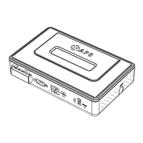
- Page 6 Install the ECU Cable Connections The following diagram is a guide for the connections on the back of the APS ECU. Power interface Serial port Network port USB interface Reset · Connect to Internet Option 1: LAN connection - use the LAN Cable to connect ECU to a Broadband Router.
- Page 7 Option 2: WiFi connection – use WiFi bridge to connect ECU to a Broadband Router. Configure the WiFi Bridge to connect to Wireless Router, please refer to WiFi Bridge User Manual Connect the RJ45 LAN Cable and USB Cable on WiFi Bridge to the RJ45 Port and USB Port on ECU The ECU needs to have a access of a Dynamic Host Configuration Protocol (DHCP) IP address which can be connected to the Internet.
- Page 8 Update after finished. For details, refer to 5.4.2 time management. Step 3: EMA Monitoring After ECU display “+web”, contact APS technical staffs in your local area and they will setup an EMA account with User Name and Password. Version:1.4...
-
Page 9: Interface Explanation
3.0 Interface Explanation 3.1 Interface position All of the ECU interface as below, from left to right, are power interface, serial port, network port and USB interface: network RS232 Power port serial interface interface port 3.2 Power Interface Power interface connects power through the power line, connection mode as below: 3.3 RS232 Serial Port The serial port works in two modes: GPRS mode and host communication mode. -
Page 10: Network Port
Host communication mode: In this mode, you can directly read data from the ECU. ECU equips with RS232 serial DB9 male interface which can be connected through the corresponding female interface or extension cord as well as by RS232 to RS485 interface converter. 3.4 Network Port RJ45 Ethernet network port: ECU allows user to communicate with EMA, and log in ECU's local page, set up the system and view the system data via Ethernet... -
Page 11: Usb Interface
ATTENTION:The historical power generaion won't be cleared. 4.0 Basic Operation The APS ECU has one two-line, 40-character LCD display with alphanumeric. Set the mode using a single button. 4.1 Power Up As soon as the ECU is plugged into an AC outlet, it will power up and display several information on screen. -
Page 12: Menu Structure
Normal Work Interface: 192.168.2.101 +Web 750W 11.54kWh 12 The number 12 indicates the number of panels to which the ECU is connected. The symbol “!” following the number 12 indicates that the number of microinverters connected to the ECU doesn’t match the number programmed into the ECU. - Page 13 Continue holding the Menu button. When the LCD displays “Device Search,” release the Menu button. The following display will appear: Searching V3.9 192.168.2.101 The ECU will automatically report inverter’s ID again. Enter the ECU menu. Hold the Menu button until the LCD displays “Status.” Release the Menu button, and the following items will be appeared: Connected: Total:...
-
Page 14: Restore The Factory Set Operation
Internet Service Provider or refer to your router documentation for troubleshooting assistance. LCD Displays “-Web”: The ECU could not connect to the APS website. · Check network connectivity to the router. You may need to contact your Internet Service Provider or refer to your router documentation for troubleshooting assistance. -
Page 15: Ecu Local Interface
5.0 ECU Local Interface Connection to APS’s web-based monitoring and analysis website (EMA) requires an Internet connection. If the users want to check data information form ECU, please make sure that the ECU is connected with internet. However, if there is... -
Page 16: Configuration
5.3 Configuration Configure the inverter protection parameters. Click “Parameters”, type the values in the “Minimum protection voltage” box, “Maximum protection voltage” box, “Minimum protection frequency” box, “Maximum protection frequency” box and “Grid Recovery Time” box, then click “Save”, the inverters’ protection parameters will be set. -
Page 17: Administration Screen
To limit the input power of the inverters, you can set the inverters’ maximum power. Click “Power Settings”, in the inverter’s “maximum power” box, type the power value, and then click “SAVE”, the inverter’s maximum power will be set, then click “Power settings” to view the actual maximum power set on the inverter in a few minutes. - Page 18 If the number of inverter ID displayed on the page is less than the actual number of inverters installed, you can enter the lost inverters ID to “Input Inverter ID” section, then click “OK”. If the number of inverter ID displayed on the page is more than the actual number of inverters installed, you can remove the redundant inverters ID from “Input Inverter ID”...
- Page 19 If the inverter ID displayed on the page is discrepancy with the actual inverters ID installed, please modified the wrong inverters ID from “Input Inverter ID” section, then click “OK”. Version:1.4...
- Page 20 Click “Clear ID”, ID will be cleared. Version:1.4...
- Page 21 Time management In date column, input date, format for day/month/year, in time column, input time, format for hour/minute/second, after the completion of the input, click on the "ok" button. The ECU also can connect to the NTP server for obtaining accurate date and time automatically.
- Page 22 address from Ethernet. To use a static IP address, you need to fulfill the IP address, Netmask, Gateway IP, Primary DNS Server and Secondary DNS Server got from network administrator. NOTE: The network cable in the package is used for the users to connect the ECU with PC directly.
-
Page 23: Technical Data
6.0 Technical Data Model: Three-phase ECU-3 Communication Interface Power Line Five core power line Ethernet 10/100M Auto-sensing, Auto-negotiation USB interface Standard RS232 Standard Power Requirements AC Outlet 120V/280V or 230V/400V, 50~60 Hz Power Consumption 2.5 W Mechanical Data Dimensions(W×H×D) 182 mm×113 mm×42 mm Weight 380 g Ambient Temperature... - Page 24 Disposal of your old appliance When this crossed-out wheeled bin symbol is attached to a product, it means the product is covered by the European Directive 2002/96/EC. All electrical and electronic products should be disposed of separately from the municipal waste stream via designated collection facilities appointed by the government or the local authorities.
-
Page 25: Contact Information
Contact Information ALTENERGY POWER SYSTEM Inc. 1 Yatai Road, Jiaxing, PR China 314050 Phone: +86-21-68889199 Fax: +86-21-33928752 www.APSmicroinverter.com Version:1.4...
Need help?
Do you have a question about the ECU-3 V3.9 and is the answer not in the manual?
Questions and answers