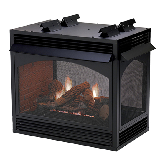
White Mountain Hearth VFP36SP32EP-1 SEE-THROUGH Installation Instructions And Owner's Manual
The vail premium vent-free multi-sided fireplaces
Hide thumbs
Also See for VFP36SP32EP-1 SEE-THROUGH:
- Installation instructions and owner's manual (40 pages)
Table of Contents
Advertisement
Quick Links
The Vail Premium Vent-Free
Multi-Sided Fireplaces
ANSI Z21.11.2 Gas Fired Decorative Type Unvented Room
Heaters.
Installer: Leave this manual with the appli-
ance.
Consumer: Retain this manual for future refer-
ence.
WARNING: If the information in these in-
structions are not followed exactly, a fire or ex-
plosion may result causing property damage,
personal injury or loss of life.
— Do not store or use gasoline or other flamma-
ble vapors and liquids in the vicinity of this or
any other appliance.
— WHAT TO DO IF YOU SMELL GAS
•
Do not try to light any appliance.
•
Do not touch any electrical switch; do not
use any phone in your building.
•
Immediately call your gas supplier from a
neighbor's phone. Follow the gas suppli-
er's instructions.
•
If you cannot reach your gas supplier, call
the fire department.
— Installation and service must be performed
by a qualified installer, service agency or the
gas supplier.
INSTALLATION INSTRUCTIONS
AND OWNER'S MANUAL
SEE-THROUGH FIREPLACE MODELS:
VFP36SP32EN-1
VFP36SP32EP-1
PENINSULA FIREPLACE MODELS:
VFP36PP32EN-1
VFP36PP32EP-1
GAS-FIRED
U.L. FILE: MH46389
This appliance may be installed in an aftermarket,
permanently located, manufactured (mobile) home,
where not prohibited by local codes.
This appliance is only for use with the type of gas
indicated on the rating plate. This appliance is not
convertible for use with other gases.
This is an unvented gas-fired heater. It uses air (oxy-
gen) from the room in which it is installed. Provisions
for adequate combustion and ventilation air must be
provided. Refer to page 8.
WARNING: If not installed, operated and maintained
in accordance with the manufacturer's instructions,
this product could expose you to substances in fuel or
from fuel combustion which can cause death or seri-
ous illness.
WATER VAPOR: A BY-PRODUCT OF UNVENTED
ROOM HEATERS
Water vapor is a by-product of gas combustion. An
unvented room heater produces approximately one (1)
ounce (30ml) of water for every 1,000 BTU's (.3KW's)
of gas input per hour. Refer to page 8.
Page 1
Advertisement
Table of Contents

Subscribe to Our Youtube Channel
Related Manuals for White Mountain Hearth VFP36SP32EP-1 SEE-THROUGH


Summary of Contents for White Mountain Hearth VFP36SP32EP-1 SEE-THROUGH
-
Page 1: Installation Instructions
INSTALLATION INSTRUCTIONS AND OWNER'S MANUAL The Vail Premium Vent-Free SEE-THROUGH FIREPLACE MODELS: VFP36SP32EN-1 Multi-Sided Fireplaces VFP36SP32EP-1 PENINSULA FIREPLACE MODELS: VFP36PP32EN-1 VFP36PP32EP-1 GAS-FIRED U.L. FILE: MH46389 ANSI Z21.11.2 Gas Fired Decorative Type Unvented Room Heaters. Installer: Leave this manual with the appli- ance. -
Page 2: Table Of Contents
TABLE OF CONTENTS SECTION PAGE Carton Contents ........................3 Hardware Package ........................3 Important Safety Information ....................4 Safety Information for Users of LP-Gas ................5 Introduction ..........................6 Specifications .........................7 Water Vapor: A By-Product of Unvented Room Heaters ............8 Provisions for Adequate Combustion & Ventilation Air ............ 8-9 Gas Supply ...........................10 Clearances ........................ -
Page 3: Carton Contents
CARTON CONTENTS Fireplace Assembly Lava Rock Package Soot Warning Sheet Installation Package Rockwool Packet Installation Instructions Serial Number Tag Warranty Card Hardware Package (See Figure Below) Nailing Flange #10 x 1/2" Phillips Hex Head Screw #10 x 1/2" Phillips Truss Head Screw Romex Connector HARDWARE PACKAGE #10 X ½”... -
Page 4: Important Safety Information
IMPORTANT SAFETY INFORMATION • An unvented room heater having an input rating of more than • Correct installation of the ceramic fiber logs, proper 6,000 Btu per hour shall not be installed in a bathroom location of the heater and annual cleaning are necessary to •... -
Page 5: Safety Information For Users Of Lp-Gas
SAFETY INFORMATION FOR USERS OF LP-GAS Propane (LP-Gas) is a flammable gas which can cause fires by point with the members of your household. Someday when and explosions. In its natural state, propane is odorless and there may not be a minute to lose, everyone's safety will depend colorless. -
Page 6: Introduction
INTRODUCTION Instructions to Installer Installation on Rugs and Tile 1. Installer must leave instruction manual with owner after If this appliance is installed directly on carpeting, tile or other installation. combustible material other than wood flooring the appliance shall 2. Installer must have owner fill out and mail warranty card supplied be installed on a metal or wood panel extending the full width and with unvented room heater. -
Page 7: Specifications
SPECIFICATIONS Model VFP36(SP,PP)32EN (NAT) VFP36(SP,PP)32EP (LP) Input Maximum 38,000 38,000 Minimum 25,000 30,000 Overall Dimensions Height without standoff 37 3/4" 37 3/4" Width 39" 39" Depth 24" 24" Gas Inlet 3/8" 3/8" Log Sets (Ordered Separately) LSU24RR-2 Rock Creek Logs Accessories EK-1 Embers Kit... -
Page 8: Water Vapor: A By-Product Of Unvented Room Heaters
WATER VAPOR: A BY-PRODUCT OF UNVENTED ROOM HEATERS Water vapor is a by-product of gas combustion. An unvented room The following steps will help insure that water vapor does not heater produces approximately one (1) ounce (30ml) of water for become a problem. -
Page 9: Provisions For Adequate Combustion & Ventilation Air
PROVISIONS FOR ADEQUATE COMBUSTION & VENTILATION AIR (continued) The space in the above example is a confined space because the Ventilation Air From Outdoors (Figure 2) actual BTU/Hr used is more than the maximum BTU/HR the space Provide extra fresh air by using ventilation grills or ducts. You must can support. -
Page 10: Gas Supply
GAS SUPPLY Check all local codes for requirements, especially for the size and type of gas supply line required. Recommended Gas Pipe Diameter Pipe Length Schedule 40 Pipe Tubing, Type L Inside Diameter Outside Diameter Nat. L.P. Nat. L.P. 0-10 feet 1/2”... -
Page 11: Clearances
CLEARANCES Combustible material clearance from front of firebox: 36" Sidewall Clearances: The clearance from the inside of the fireplace minimum to perpendicular combustible side wall should not be less than 1 3/4". See Figures 4a and 4b. Fireplace Side and Back Clearances: The fireplace outer casing side(s) require a minimum 1/2"... -
Page 12: Combustible Materials
CLEARANCES (cont.) Ceiling Clearances: The ceiling height should not be less than 42" able for each model. If a combustible mantel is installed, it must from the top of the hood. See Figures 6a and 6b. meet the clearance requirements detailed below. Mantel Clearances: Vent free fireplace models must use the hood Leave furniture and other combustible items at least 36"... -
Page 13: Planning Installation
PLANNING INSTALLATION If the fireplace is installed directly on carpeting, tile or other In planning the installation for the fireplace, it is necessary to combustible material other than wood flooring, it should be installed determine where the unit is to be installed and whether optional on a metal or wood panel extending the full width and depth of accessories are desired. - Page 14 FIREPLACE INSTALLATION INSTRUCTIONS (continued) 2 9/16” 2 9/16” 2 9/16” SEE THRU PENINSULA LOUVERED LOUVERED VFP36SP VFP36PP 34 3/4" 34 3/4" 39" 39" 24" 24" 22" 22" 36" 36" 34 1/4" 35 1/4" 29 1/8" 29 1/8" 37 3/4" 37 3/4" 1 1/4"...
- Page 15 FIREPLACE INSTALLATION INSTRUCTIONS (continued) Locating Fireplace Place fireplace in framed opening. Attach the framing brackets to the fireplace and secure to framing. Different hole locations can be used for finishing materials with thicknesses of 3/8", 1/2" and 3/4". Secure the brackets with screws provided using two (2) per framing bracket.
-
Page 16: Installing Hoods
INSTALLING HOODS Black hoods are furnished with each fireplace (or the optional Extended Hoods hood(s)) and MUST be installed before the fireplace is used. Failure If your non-combustible facing material is over 1" in thickness and to do so may create a possible fire hazard. For shipping purposes, will be used to finish this fireplace, extended hoods are available the hoods are located behind the upper or lower louvers. -
Page 17: Gas Line Connection
GAS LINE CONNECTION The fireplace is designed to accept a gas line for connection to the gas valve. Have the line installed by a qualified service person in accordance with all building codes. Consult local building codes to properly size the gas supply line leading to the connection of the valve. -
Page 18: Placement Of Glowing Embers And Lava Rock
PLACEMENT OF GLOWING EMBERS AND LAVA ROCK Placing Lava Rock in Front of Burner on Fireplace Floor Placement of the glowing embers (rockwool) is very individual and light coverage of the areas indicated will provide your best effects. Spread lava rocks on fireplace floor in front of the burner pan. We recommend separation of the rockwool by hand and to make The lava rocks are for decorative effect and are not required for your coverage as light and fluffy as possible. -
Page 19: Operation Instructions/Flame Appearance
OPERATION INSTRUCTIONS/FLAME APPEARANCE Before you begin: Do not handle the logs with your bare hands! components of this appliance are treated with certain oils, films or Always wear gloves to prevent skin irritation. After handling logs, bonding agents. These chemicals are not harmful, but may produce wash your hands gently with soap and water. -
Page 20: Vfp36(Sp,Pp)32 Lighting Instructions
VFP36(SP,PP)32 LIGHTING INSTRUCTIONS FOR YOUR SAFETY READ BEFORE LIGHTING WARNING: If you do not follow these instructions exactly, a fire or explosion may result caus- ing property damage, personal injury or loss of life. A. This appliance has a pilot which must be lighted by •... -
Page 21: Burner Instructions
BURNER INSTRUCTIONS Check the following items during installation prior to • For best results when lighting the burner, have your lighting the multisided burner: adjustable flame knob to the HI position, then adjust to a lower setting after the burner has ignited. •... -
Page 22: Pilot Flame Characteristics
PILOT FLAME CHARACTERISTICS Figure 16 show a correct pilot flame pattern. The correct flame Cleaning and Pilot Maintenance will be blue and will extend beyond the thermocouple. The flame Oxygen Depletion Sensor Pilot (Figure 18) will surround the thermocouple just below the tip. A slight yellow When the pilot has a large yellow tip flame, clean the Oxygen flame may occur where the pilot flame and main burner flame Depletion Sensor as follows:... -
Page 23: Wiring
WIRING Label all wires prior to disconnection when servicing controls. Remote Receiver Wiring errors can cause improper and dangerous operation. Verify Use the following steps to place the remote receiver adjacent to the gas valve. proper operation after servicing. Attention: The remote receiver bracket is not used in this Millivolt thermopile is self powered, gas valve does not require 110 installation. -
Page 24: Troubleshooting Symptoms - Possible Causes And Solutions
TROUBLESHOOTING SYMPTOMS - POSSIBLE CAUSES AND CORRECTIONS Turn appliance OFF and allow to cool before servicing. Only a qualified service person should service and repair the heater. 7. ODS/pilot lights but flame goes out when control knob is 1. When ignitor button is pressed, there is no spark at ODS/ released. -
Page 25: Wiring Instructions For Installing A Dual Switch/Receptacle
WIRING INSTRUCTIONS FOR INSTALLING A DUAL SWITCH / RECEPTACLE In order to install both the optional Blower and Accent Light ac- CAUTION: ALL WIRING SHOULD BE DONE BY A QUAL- cessories, it will be necessary to install the junction box so that IFIED ELECTRICIAN AND SHALL BE IN COMPLIANCE the Duplex Receptacle wiring is split. - Page 26 OPTIONAL FBB5 BLOWER INSTALLATION INSTRUCTIONS To install the blower kit, access the junction box, or install a light Attention: Install blower assembly before connecting gas in- kit, remove lower louver as illustrated by figure 21. let supply line. A factory included junction box is located on the lower right side Wiring of the fireplace.
-
Page 27: Optional Blower Installation Instructions
OPTIONAL BLOWER INSTALLATION INSTRUCTIONS (continued) Note: This blower is equipped with a heat activated fan control Insert blower assembly into interior, bottom of firebox. switch. Blower will operate when the fireplace warms up, Note: On peninsula models, the blower must be installed at and will turn off automatically when the fireplace cools the end which has the brick panel installed. -
Page 28: Optional Blower Installation Instructions
OPTIONAL BLOWER INSTALLATION INSTRUCTIONS (continued) Blower Motor Wiring The blower motor does not have oiling holes. Do not attempt to The appliance, when installed, must be electrically grounded in oil the blower motor. accordance with local codes or, in the absence of local codes, with the National Electrical Code, ANSI/NFPA 70, if an external Blower Wheels electrical source is utilized. -
Page 29: Lk2 Accent Light Accessory
LK2 ACCENT LIGHT ACCESSORY An Accent Light Kit model LK2 is available for installation in the top of the firebox. Providing the junction box has been pre-wired with separate circuits as described in the "Wiring for a dual switch/receptacle" section. Follow the instructions provided with the LK2 Accent Light kit for proper installation in the fireplace. -
Page 30: Parts List
PARTS LIST ATTENTION: When ordering parts, it is very important that part number and description of part coincide. PART NUMBER INDEX DESCRIPTION NUMBER VFP36SP32EN VFP36SP32EP VFP36PP32EN VFP36PP32EP 17301 17301 17301 17301 TOP STANDOFF R3491 R3491 R3491 R3491 COVER, JUNCTION BOX R3492 R3492 R3492... -
Page 31: How To Order Repair Parts
PARTS LIST ATTENTION: When ordering parts, it is very important that part number and description of part coincide. PART NUMBER INDEX DESCRIPTION NUMBER VFP36SP32EN VFP36SP32EP VFP36PP32EN VFP36PP32EP 23244 23244 23244 23244 VENTURI SHIELD R3435 R3435 R3435 R3435 WIRE ASSEMBLY R3436 R3436 R3436 R3436... -
Page 32: See-Through Fireplace Parts View
SEE-THROUGH FIREPLACE PARTS VIEW 17 18 19 22 NAT. BURNER N a t G 36 37 Page 32 24309-1-0908... -
Page 33: Peninsula Fireplace Parts View
PENINSULA FIREPLACE PARTS VIEW 17 18 19 22 LP BURNER NAT. BURNER N a t G 36 37 24309-1-0908 Page 33... -
Page 34: Accessories
ACCESSORIES Accessory Description Model Numbers Fan Kit Designed to provide forced air flow. FBB5 Variable Speed Control Kit Wall mounted variable speed control for use with SCV-1 FBB5 blower Frame Kits Standard 3-Piece Frame Kits Black, Brass, Stainless Steel, or Hammered Pewter For use with See-Through models: VFP36SP32 SERIES ONLY Contact dealer for all available... -
Page 35: Accessories
ACCESSORIES (continued) Accessory Description Model Numbers Accent Light Kit Optional light kit that installs in top of firebox to enhance logset. Operates with a Rheostat control to vary brightness of light for desired effect. Extended 4" Hoods Extended hoods that extend out 2" farther than the stan- dard hoods, to accommodate thicker surround materials. -
Page 36: Service Notes
SERVICE NOTES Page 36 24309-1-0908... -
Page 37: Reference
Web Site: www.empirecomfort.com Empire Comfort Systems 918 Freeburg Avenue Belleville, Illinois 62220-2623 The Vail Premium Vent-Free Fireplaces GAS-FIRED SEE-THROUGH FIREPLACE MODELS: VFP36SP32EN-1 VFP36SP32EP-1 PENINSULA FIREPLACE MODELS: VFP36PP32EN-1 VFP36PP32EP-1 36-inch Fireplace accommodates the following Log Set: Refractory Log Set: LSU-24RR-2 Banded Brick Liners are made from Ceramic Fiber for rich detail and lasting beauty. Banded Brick Liners have dark "creamed-coffee"... - Page 38 Web Site: www.empirecomfort.com Empire Comfort Systems 918 Freeburg Avenue Belleville, Illinois 62220-2623 The Vail Premium Vent-Free Fireplaces SEE-THROUGH FIREPLACE MODELS: PENINSULA FIREPLACE MODELS: VFP36SP32EN-1 VFP36PP32EN-1 VFP36SP32EP-1 VFP36PP32EP-1 Clearances Combustible material clearance (furniture, parallel walls) from front of fireplace: 36" minimum Sidewall Clearances: The clearance from the inside opening of the firebox to perpendicular combustible side wall should not be less than 1 3/4".
- Page 39 Web Site: www.empirecomfort.com Empire Comfort Systems 918 Freeburg Avenue Belleville, Illinois 62220-2623 The Vail Premium Vent-Free Fireplaces SEE-THROUGH FIREPLACE MODELS: PENINSULA FIREPLACE MODELS: VFP36SP32EN-1 VFP36PP32EN-1 VFP36SP32EP-1 VFP36PP32EP-1 Clearances (continued) Framing 1 3/4” MIN. 42” PERPENDICULAR MIN. COMBUSTIBLE (CEILING TO SIDEWALL TOP OF HOOD) Framing - Peninsula 36”...
- Page 40 Empire Comfort Systems Inc. EMPIRE EMPIRE 918 Freeburg Ave. Belleville, IL 62220 If you have a general question about our products, please e-mail us at info@empirecomfort.com. If you have a service or repair question, please contact your dealer. Comfort Systems www.empirecomfort.com Page 40 24309-1-0908...
Need help?
Do you have a question about the VFP36SP32EP-1 SEE-THROUGH and is the answer not in the manual?
Questions and answers