Table of Contents
Advertisement
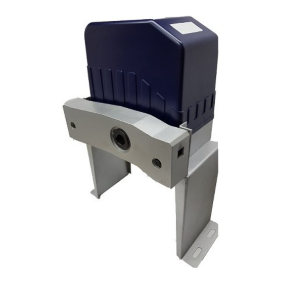
Residential Sliding Gate Opener
(Magnetic L i m it Switch – Chain type)
Installation and Owner's Manual
For Residential use only – Class 1
( A Ve hic ula r ga t e op e r a tor int e nd e d for use in a s ingle f a m i l y dwe l l i n g )
Made in the U.S.A.
This Product meets and exceeds the requirements of UL 325, the standard which regulates
gate operator safety, as established and made effective March 1, 2000, by Underwriters Laboratories Inc.
C
A
U
T
I
O
N
:
P
L
E
A
S
E
R
E
A
D
T
H
S I
M
A
N
U
A
L
C
A
R
E
F
U
L
L
Y
GATEMOTORS INC.
Email: GATEMOTOR@YAHOO.COM
WWW.GATEMOTORS.COM
Advertisement
Table of Contents

Subscribe to Our Youtube Channel
Related Manuals for Viper TC-3


Summary of Contents for Viper TC-3
- Page 1 Residential Sliding Gate Opener (Magnetic L i m it Switch – Chain type) Installation and Owner’s Manual For Residential use only – Class 1 ( A Ve hic ula r ga t e op e r a tor int e nd e d for use in a s ingle f a m i l y dwe l l i n g ) Made in the U.S.A.
-
Page 2: Table Of Contents
Residential Sliding Gate Operator Table of Contents Table of Contents........................ 1 Safety Alert Symbols ......................4 Description of your Gate Opener ..................5 FEATRUES ........................5 SAFETY ......................... 5 SPECIFICATIONS......................5 OPTION(S) ........................6 Packing List ........................6 Tools you will need......................7 Installation Instruction ...................... -
Page 3: Safety Alert Symbols
Residential Sliding Gate Operator Safety Alert Symbols Start here and read these important safety rules for the SLIDE Gate Opener These safety alert symbols mean CAUTION – Personal safety, property damage or danger from electrical shock. Read these instructions carefully Failure to comply with the following instructions may result in serious injury, including death or property damage. -
Page 4: Description Of Your Gate Opener
Residential Sliding Gate Operator Description of your SLIDE Gate Opener FEATRUES • Weather proof casing • Reliable magnetic limit switches for accura te open and close gate positions. • Self-locking gear motor in both open and close positions. • 300 mhz receiver. •... - Page 5 SLIDE GATE OPENER...
- Page 6 MODEL: COMPONENT COMPONENT MFR’S PART NO. QUANTITY DESCRIPTION MANUFACTURER Cover tc3cov1 Set Phillips screw tc3sps2 1/2 h.p. Motor tc3mot3 Limit magnets tc3lm4 Control board tc3c/b5 tc3cap6 Capacitor L-brackets tc3lb7 Plastic clip tc3pc8 Base plate for receiver/ tc3bp9 limit switch sensor Base plate for control board tc3bp10 Plastic clips...
-
Page 7: Tools You Will Need
Residential Sliding Gate Operator Tools you will need During assembly and installation of your opener, the instructions will call for the use of various tools shown below. Other tools may be required as needed for the installation of the concrete pad and electrical connection. Table 3 Required Tools for Installation Screwdriver Tape Measure... - Page 8 Step #1 Unscrew the Blue Cover from the Motor and set it aside. Open the small white box & make sure that the contents include: (1) - Receiver and (1) - Control Board Step #2 Install the Control Board onto the Motor by mounting it on the small white clips that are on the large Mounting Plate.
- Page 9 MAKING THE CONNECTION Step #4 Now you will begin the installation by screwing the wires that are coming from the small Receiver Board onto the Terminals (see Pic 1, right) from the Control Board, in the following order: Terminal 10 - GREEN WIRE Terminal 11 - RED WIRE Terminal 12 - YELLOW WIRE (any) Terminal 13 - YELLOW &...
- Page 10 Step #6 Find the plug with the Blue & Yellow wires on it. Connect the plug on to the Control Board on the section labeled: "CAPACITOR" (as shown on the pic, right) Step #7 Find the plug with the Red, White & Blue wires on it. Connect the plug on to the Control Board on the section labeled: "LIMIT SWITCH"...
- Page 11 AC SLIDE GATE CONTROLLER FEATURE SELECTOR Limit Switch Type DIP 1 ON: Normally Close OFF: Normally Open When using auto close features only one dip switch should be it h h ld b Auto Close Feature Auto Close Feature DI P 2 12.5 Seconds ON.
-
Page 12: Concrete Pad
SLIDING GATE OPERATOR Anchors You can use the anchors that are provided with the operator, 3 ¾ anchor bolts (4), anchors, washers, and nuts. These anchors must be set into the concrete when it is poured, or you can use wedge anchors (1/4” x 4”). Operator Base Mount the gate operator base to the concrete pad. - Page 13 SLIDING GATE OPERATOR Fig.3 Chain Brackets Use the appropriate bolts to attach the chain bracket to the frame of the gate. If the gate is of square frame style, use the square bolts shown. Gate Square frame Plain washer ( Φ 6) Square bolt Spring washer ( Φ...
- Page 14 SLIDING GATE OPERATOR Chain Close the gate and attach a chain bolt to the piece of chain that comes with the chain box using enclosure master links. Tighten the chain bolt to the bracket with washers and nuts. Pull the chain through the chain wheel box to the other chain bracket at the opposite end of the gate.
-
Page 15: Electrical Preparation
Residential Sliding Gate Operator Figure 1, Platform Base Dimensions Electrical Preparation Install a suitable electrical outlet box that will be used to supply power to the Operator. This box should be located near the operator, approx. 24” from the platform, and out of the path of the gate. -
Page 16: Gate Operator Mechanical Installation
Residential Sliding Gate Operator As an option, a standard three prong cord (minimum 14 gauge), suitable for use in a harsh environment, can be connected into the Outdoor Box protected with a GFCI receptacle. If using this configuration, be sure to install a weather proof cover on the Outdoor Electrical box to protect the GFCI receptacle from moisture. - Page 17 Residential Sliding Gate Operator 14. Position the Operator and Chain Box approximately one half inch (½”) from the Gate as measured from the front of the Chain Box to the gate, see Figure 1. 15. Install the four bolts securing the Opener to the Base, and tighten with wrench. 16.
-
Page 18: Gate Operator Electrical Installation
GFCI receptacle. 1. Ensure that the electricity to the Outlet Box is OFF. 2. Check the Power switch on the Viper Control Board. Switch to the OFF position “O/I” with “O” switch position down). -
Page 19: Radio Transmitter Controls
Residential Sliding Gate Operator 9. On the SLIDE Control board, turn on the Power Switch by pressing the switch to the “I” position down. 10. Verify that the Power indicator (31) on the Control Board is lit. See Figure 3. 11. - Page 20 Residential Sliding Gate Operator In this configuration, the tail extension was made from the same material as the gate, 1- ½” square tubing, and is 12” long and 10” high. At the right side, the chain bolt plate was wielded on at the shop as were the two U clamps that attach the extension to the gate (left).
-
Page 21: Manual Release
Residential Sliding Gate Operator Manual Release Your Slide gate opener will include two keys that are used to disengage the operator from your gate in case of an emergency or power outage. Turn counter-clock-wise in the slot above to disengage the operator from the gate. This will allow you to use the gate manually. -
Page 22: Optional Equipment Installation Procedures
Residential Sliding Gate Operator Optional Equipment Installation Procedures Green Brown Black Blue Brown Black White Grey Grey Black Black...
Need help?
Do you have a question about the TC-3 and is the answer not in the manual?
Questions and answers