Table of Contents
Advertisement
VIPER TC-9
Residential Sliding Gate Opener
(Magnetic Limit Switch – Chain type)
Installation and Owner's Manual
For Residential use only – Class 1
(A Vehicular gate operator intended for use in a single family dwelling)
Made in the U.S.A.
This Product meets and exceeds the requirements of UL 325, the standard which regulates
gate operator safety, as established and made effective March 1, 2000, by Underwriters Laboratories Inc.
CAUTION: PLEASE READ THIS MANUAL CAREFULLY
GATEMOTORS INC.
PHONE: (352)241-8259
Email: Sales@Vipergatesystems.com
Advertisement
Table of Contents

Subscribe to Our Youtube Channel
Related Manuals for Viper TC-9


Summary of Contents for Viper TC-9
- Page 1 VIPER TC-9 Residential Sliding Gate Opener (Magnetic Limit Switch – Chain type) Installation and Owner’s Manual For Residential use only – Class 1 (A Vehicular gate operator intended for use in a single family dwelling) Made in the U.S.A. This Product meets and exceeds the requirements of UL 325, the standard which regulates gate operator safety, as established and made effective March 1, 2000, by Underwriters Laboratories Inc.
- Page 2 TC-9 Viper ™ Gate System Residential Sliding Gate Operator This page intentionally left blank.
-
Page 3: Table Of Contents
Figure 1, Platform Base Dimensions .................. 9 Figure 2, Viper TC-9 Configuration Diagram ..............16 Figure 3, Viper TC-9 Control Board Terminals, Indicators and Jumpers ......17 Figure 4 Typical Gate Extension for TC-9 Operator ............18 Figure 5 Viper TC-9 Electrical Connection..............19 Table 1, Viper TC-9 Specification.................. -
Page 4: Safety Alert Symbols
Residential Sliding Gate Operator Safety Alert Symbols Start here and read these important safety rules for the TC-9 Viper Gate Opener These safety alert symbols mean CAUTION – Personal safety, property damage or danger from electrical shock. Read these instructions carefully Failure to comply with the following instructions may result in serious injury, including death or property damage. -
Page 5: Description Of Your Tc-9 Viper Gate Opener
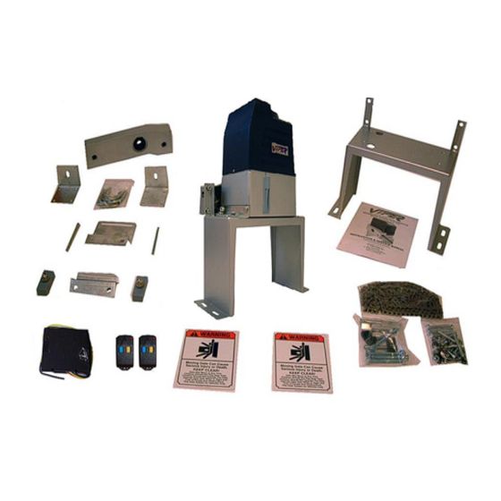
TC-9 Viper ™ Gate System Residential Sliding Gate Operator Description of your TC-9 Viper Gate Opener FEATURES Weather proof casing Reliable magnetic limit switches for accurate open and close gate positions. Self-locking gear motor in both open and close positions. - Page 6 TC-9 Viper ™ Gate System Residential Sliding Gate Operator TC-9...
- Page 7 TC-9 MODEL: COMPONENT COMPONENT MFR’S PART NO. QUANTITY DESCRIPTION MANUFACTURER Viper Gate Systems Cover tc9cov1 Viper Gate Systems U – bolts tc9ub2 Viper Gate Systems ¾ h.p. Motor tc9mot3 Viper Gate Systems Limit magnets tc9lm4 Viper Gate Systems Control board...
-
Page 8: Tools You Will Need
TC-9 Viper ™ Gate System Residential Sliding Gate Operator Tools you will need During assembly and installation of your opener, the instructions will call for the use of various tools shown below. Other tools may be required as needed for the installation of the concrete pad and electrical connection. - Page 9 MAIN BOARD / TERMINAL BLOCK 13 14 LIMIT LIMIT SWITCH CAPACITOR RECEIVER YELLOW / GREEN – Ground (ter. #22) MOTOR...
-
Page 10: Installation Instruction
(not supplied) by drilling four holes into the concrete pad after it has set up. Operator Base Position the Viper TC-9 platform on top of the pad, then mark the hole positions (3” On- Center) which will allow ±¾” of adjustment for proper alignment of the Operator with the correct distance from the gate, See Figure 1, Platform Base Dimensions. -
Page 11: Electrical Preparation
Figure 1, Platform Base Dimensions Electrical Preparation Install a suitable electrical outlet box that will be used to supply power to the TC-9 Operator. This box should be located near the operator, approx. 24” from the platform, and out of the path of the gate. Wire size should be 12 gauge two conductor wires with a Ground and protected by a Ground Fault Circuit Interrupt (GFCI). -
Page 12: Gate Operator Mechanical Installation
As a general rule, the cord should be less than six feet in length, Gate Operator Mechanical Installation The Viper TC-9 Gate Operator is easily installed for a sliding gate, either left-hand or right-hand opening. The instructions that follow are for a typical installation, and provide a fair amount of detail for a complete operating gate opener. - Page 13 TC-9 Viper ™ Gate System Residential Sliding Gate Operator 16. Install the two Chain bolts, U-bolt clamps and brackets to the gate as illustrated in Figures 1 & 4. One is installed on the right side of the Gate, the other on the left side, preferable on the outer gate frame.
-
Page 14: Gate Operator Electrical Installation
If the circuit us functioning properly, proceed to the next step. If not, recheck the GFCI receptacle installation and isolate the problem. 9. On the Viper TC-9 Control board, turn on the Power Switch by pressing the switch to the “I” position down. -
Page 15: Radio Transmitter Controls
“tail” to be added to the gate to accommodate the installation of the rear chain bolt to the gate. This is illustrated in Figure 4, Typical Gate Extension for TC-9 Operator. It would require wielding or attaching an extension to the gate. In this case, the minimum extension must extend 8”... - Page 16 TC-9 Viper ™ Gate System Residential Sliding Gate Operator In this configuration, the tail extension was made from the same material as the gate, 1- ½” square tubing, and is 12” long and 10” high. At the right side, the chain bolt plate was wielded on at the shop as were the two U clamps that attach the extension to the gate (left).
- Page 17 Receiver/Remote Control Instructions When power is on green light on receiver should light up 1. When power is on green light on receiver should light up 1. When power is on green light on receiver should light up 2. Push Learn button and red light comes on 3. Choose 1 out of the 4 buttons on the Key Chain Remote Control. 4. Press the number that you chose to be your button until the red light on receiver is off and then let go 5. Press the number button that you have chosen on the remote again. Red light blinks rapidly then let go (at this point remote is programmed to your receiver) 6. Finally, Press the button for the third time you should get a response that means the gate opener is working. Push learn button red light comes on Choose 1 out of the 4 buttons on the Key Chain Remote Control Press the number that you chose to be your button until the red light on receiver is off ...
- Page 18 3. Press the Remote Yellow button and verify that the new selected codes operate the gate. 4. Replace TC-9 Viper Gate Opener plastic cover and secure with the three screws. 5. Your Gate radio transmitter controls setting are complete. Figure 2, Viper TC-9 Configuration Diagram...
- Page 19 TC-9 Viper ™ Gate System Residential Sliding Gate Operator Figure 4 Typical Gate Extension for TC-9 Operator...
- Page 20 TC-9 Viper ™ Gate System Residential Sliding Gate Operator Figure 5 Viper TC-9 Electrical Connection...
- Page 21 TC-9 Viper ™ Gate System Residential Sliding Gate Operator...
-
Page 22: Adjustment And Maintenance
Note: Keep the Clutch Key near the Opener so you can locate it easily if there is a power failure. Attach the Clutch Key to the GFCI outlet box that is nearby. 7. Change the Security Codes Yearly in both the Viper Control Board and the Remote Openers. -
Page 23: Having A Problem
Does the operator have electrical power? Check the electrical outlet for power. Remove the Viper TC-9 cover and check the power indicator light 31. Check for obstruction in the Sensor Beam path Check the Fuse 33 with an ohm meter. -
Page 24: Limited Warranty
TC-9 Viper ™ Gate System Residential Sliding Gate Operator Limited Warranty You must read, understand and agree with items in the Limited Warranty. GATEMOTORS INC. Warrants the Sliding Gate Operator to be free of defects in workmanship and materials for a period of 1 year for electronics, mechanical components and chassis for perforation due to corrosion and 2 year warranty on motor.
Need help?
Do you have a question about the TC-9 and is the answer not in the manual?
Questions and answers