Pfaff 1525 Instruction Manual
Hide thumbs
Also See for 1525:
- Owner's manual (56 pages) ,
- Instruction manual (58 pages) ,
- Instruction manual (96 pages)

Related Manuals for Pfaff 1525


Summary of Contents for Pfaff 1525
-
Page 1: Instruction Manual
1525 1525-S Instruction Manual 1525-G 1526 This instruction manual applies to machines from the following serial numbers onwards: # 2722168 296-12-18 596/002 Betriebsanleitung engl. 08.06... - Page 2 As an alternative to the internet download the adjustment manual can also be ordered in book form under part no. 296-12-18 597/002. The reprinting, copying or translation of PFAFF Instruction Manuals, whether in whole or in part, is only permitted with our previous authorization and with written reference to the source.
-
Page 3: Table Of Contents
Knee switch ....................... 7 - 2 Presser foot fixing key ....................7 - 3 Adjusting the stitch length (on thePFAFF 1525 and 1526) .......... 7 - 3 Adjusting the stitch length (on thePFAFF 1525-S) ............7 - 4 Reverse-feed control ....................7 - 4... -
Page 4: Contents
Bobbin-changing/threading, and regulating the bobbin thread tension ....... 9 - 3 Threading needle thread and regulating its tension on the PFAFF 1525 ..... 9 - 4 Threading needle threads and regulating tensions on the PFAFF 1526 ..... 9 - 5 Care and maintenance ................... - Page 5 Contents Contents ................Chapter - Page Mounting the table top and Circuit diagrams ............11 - 1 Table top cutout ....................... 11 - 1 Mounting the table top ..................... 11 - 2 Circuit diagrams ....................... 11 - 3 Wearing parts ......................... 12 - 1...
-
Page 6: Safety
Safety Safety Regulations This machine is constructed in accordance with the European regulations indicated in the conformity and manufacturer's declarations. In addition to this instruction manual, please also observe all generally accepted, statutory and other legal requirements, including those of the user's country, and the applicable pol- lution control regulations! The valid regulations of the regional social insurance society for occupational accidents or other supervisory authorities are to be strictly adhered to! -
Page 7: Safety Symbols
The user must ensure that none of the safety devices are removed nor put out of work- ing order. The user must ensure that only authorized persons operate and work on the machine. For further information please refer to your PFAFF agency. 1 - 2... -
Page 8: Notes For Operating And Technical Staff
Safety Notes for operating and technical staff Operating staff .05.01 Operating staff are the persons responsible for setting up, operating and cleaning the mach- ine and for removing any disturbances in the sewing area. The operating staff are obliged to observe the following points, and must: always observe the notes on safety in this instruction manual! avoid using any working methods which adversely effect the safety of the machine! avoid wearing loose-fitting clothing or jewelry such as necklaces or rings! -
Page 9: Danger Warnings
Safety Danger warnings A working area of 1 m must be kept free both in front of and behind the mach- ine, so that easy access is possible at all times. Never put your hands in the sewing area during sewing! Danger of injury by the needle! While setting or adjusting the machine do not leave any objects on the table nor in the needle plate area! Objects may be trapped or slung out of the mach-... -
Page 10: Proper Use
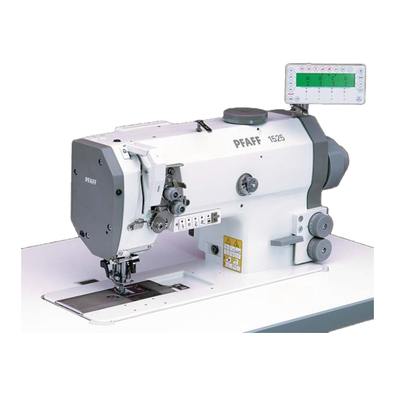
Proper use Proper use The PFAFF 1525 and PFAFF 1525-S are single needle, special high-speed lockstitch sewing machines with unison feed and a large hook. The PFAFF 1525-G is a single needle, special high-speed lockstitch sewing machines with unison feed and an extra large hook. -
Page 11: Specifications
Motordaten: ................. siehe Typenschild des Motors Air consumption per working cycle:: ..............0,146 Nl Net weight of sewing head, PFAFF 1525: ............approx. 50 kg Net weight of sewing head, PFAFF 1526: ............approx. 52 kg Gross weight, PFAFF 1525: ................approx. 58 kg Gross weight, PFAFF 1526: ................ - Page 12 4,5 - 5 mm 2200 2200 2200 5,5 - 7 mm 1800 1800 1800 Top feed PFAFF 1526 Max. sewing speed in s.p.m. at needle gauges: stroke 6 mm 12 mm 20 mm 28 mm 40 mm 1 mm 3800...
-
Page 13: Disposal Of Machine
Disposal of Machine Disposal of Machine Proper disposal of the machine is the responsibility of the customer. The materials used for the machine are steel, aluminium, brass and various plastic materials. The electrical equipment comprises plastic materials and copper. The machine is to be disposed of according to the locally valid pollution control regula- tions;... -
Page 14: Transportation, Packing And Storage
Transportation, packing and storage Transportation, packing and storage Transportation to customer's premises The machines are delivered completely packed. Transportation inside the customer's premises The manufacturer cannot be made liable for transportation inside the customer's premises nor to other operating locations. It must be ensured that the machines are only transported in an upright position. -
Page 15: Explanation Of Symbols
Explanation of symbols Explanation of symbols In this instruction manual, work to be carried out or important information is accentuated by symbols. These symbols have the following meanings: Note, information Cleaning, care Lubrication Maintenance, repairs, adjustment, service work (only to be carried out by technical staff) 6 - 1... -
Page 16: Controls
Switch machine on or off by turning on/- off switch 1. Fig. 7 - 01 Keys on machine head (no keyboard on the PFAFF 1525-S) The keys on the machine head are pres- sed to set off certain functions. Key 1:... -
Page 17: Pedal
Controls Pedal 0 = Neutral position 1 = Sewing 2 = Raise presser foot 3 = Trim sewing threads Other pedal functions are listed in the instruction manual for the control panel. Fig. 7 - 03 Knee switch By operating knee switch 1 it is possible to alternate between two pre-selected feed stroke settings. -
Page 18: Presser Foot Fixing Key
To release the presser foot, raise it briefly with the pedal. Fig. 7 - 05 Adjusting the stitch length (on thePFAFF 1525 and 1526) The thumb wheels 1 and 2 can be used to pre-select the stitch lengths. The adjustment is made by pressing and at the same time turning the thumb wheels. -
Page 19: Adjusting The Stitch Length (On Thepfaff 1525-S)
Controls Adjusting the stitch length (on thePFAFF 1525-S) Adjustment wheel 1 is used to pre-select the stitch length. Fig. 7 - 06a Reverse-feed control To sew in reverse, press reverse-feed control lever 1. Fig. 7 - 07 7 - 4... -
Page 20: Edge Trimmer -731/02
Controls Edge trimmer -731/02 Keep your hands away from the moving knife! Danger of injury! Press key 1 to switch the knife drive on or off. The bartack suppression key is omitted, see Chapter 7.02 Keys on the machine head. Fig. -
Page 21: Adjusting The Top Feed Stroke
Adjustment Manual Chapter 13.05.11 Top feed lift. Fig. 7 - 10 Bobbin thread supply monitor -926/06 PFAFF 1525 When the set thread-end length is reach- ed, diode 1 flashes and the machine is stopped. PFAFF 1526 When the set thread end-length is reached, diode 1 (left bobbin) or 2 (right bobbin) flashes. -
Page 22: Bobbin Thread Control By Stitch Counting
Controls Bobbin thread control by stitch counting When the pre-set number of stitches is reached, LED 1 flashes. After a bobbin change, the "scroll" key on the control panel must be pressed. Pre-setting the number of stitches, see the instruction manual for the control panel. -
Page 23: Installation And Commissioning
Installation and commissioning Installation and commissioning The machine must only be mounted and commissioned by qualified personnel! All relevant safety regulations are to be observed! If the machine is delivered without a table, it must be ensured that the frame and the table top which you intend to use can hold the weight of the machine and the motor. -
Page 24: Assembling The Motor (Only On Machines With Quick-Motor)
Installation and commissioning Assembling the motor .01.02 (only on machines with Quick-motor) 109-001 Fig. 8 - 02 Assemble motor mounting 1, motor 2, belt guard support 3 and belt pulley 4 as shown in Fig. 8-02. Tightening the V-belt .01.03 Fit the V-belt. -
Page 25: Mounting The Bottom V-Belt Guard
Installation and commissioning Mounting the bottom V-belt guard .01.04 Fig. 8 - 04 109-071 Loosen screws 2 and adjust belt guard support 1 so that the motor pulley and V-belt run freely. Tighten screws 2. Fasten belt guard 3 with screw 4. Fig. -
Page 26: Fitting The Synchronizer
Installation and commissioning Fitting the upper V-belt guard .01.05 Screw position stop 1 to the right belt guard section 2. Attach belt guard section 3 with screws 4. Push the slots of the right belt guard section 2 behind the heads of retaining screws 6 and attach it with screws 5 and 6. -
Page 27: Fitting The Tilt Lock
Installation and commissioning Fitting the tilt lock .01.07 Screw on tilt lock 1, provided in the ac- cessories, using screw 2. Do not operate the machine without tilt lock 1! Danger of crushing between sewing head and table top! Fig. 8 - 07 Fitting the reel stand .01.08 Fit the reel stand as shown in Fig. -
Page 28: Connecting The Plug-In Connections And Earth Cables
Installation and commissioning Connecting the plug-in connections and earth cables Fig. 8 - 09 Connect all plugs as labelled to the control box 1. Screw the earth cable from the sewing head and the main switch to earth point A. Connect earth point A to earth point B with earth cable 2. -
Page 29: Installation
Installation and commissioning Installation Check the machine, particularly its electrical wiring and pneumatic tube connections, for any damage. Remove stopper 1 from oil tank 2. The stopper is only used as a transit lock and must not be used during sewing operation. -
Page 30: Basic Position Of The Machine Drive Unit
Installation and commissioning Basic position of the machine drive unit (only on machines with Quick-EcoDrive and control unit P70ED) Switch on the machine. Press the TE/speed key twice to select the input mode. Select parameter "798" by pressing the corresponding +/- key, and select service level C, see Chapter Selecting the user level in the instruction manual for the control panel. -
Page 31: Setting Up
Danger due to unintentional starting of the machine! Only use needles from the system intended for the machine, see Chapter 3 Specifications. PFAFF 1526 PFAFF 1526 Set needle bar at top position and loosen Set needle bar at top position and loosen screw 1. -
Page 32: Winding The Bobbin Thread, Regulating The Winder Tension
Setting up Winding the bobbin thread, regulating the winder tension Fig. 9 - 03 Place an empty bobbin 1 on winder spindle 2. Thread up as shown in Fig. 9 - 03 and wind the thread a few times clockwise around bobbin 1. -
Page 33: Bobbin-Changing/Threading, And Regulating The Bobbin Thread Tension
Setting up Bobbin-changing/threading, and regulating the bobbin thread tension Switch the machine off! Danger due to unintentional starting of the machine! Set take-up lever at its top position. Open bed slide, lift latch 1 and take out the bobbin. Place the filled bobbin into the hook so that the bobbin turns as shown by the arrow when the thread is pulled. -
Page 34: Threading Needle Thread And Regulating Its Tension On The Pfaff 1525
Setting up Threading needle thread and regulating its tension on the PFAFF 1525 Fig. 9 - 05 Switch the machine off! Danger due to unintentional starting of the machine! Thread the needle thread as shown in Fig. 9 - 05. -
Page 35: Threading Needle Threads And Regulating Tensions On The Pfaff 1526
Setting up Threading needle threads and regulating tensions on the PFAFF 1526 Fig. 9 - 06 Switch the machine off! Danger due to unintentional starting of the machine! Thread the needle thread as shown in Fig. 9 - 06. Regulate the needle-thread tension by turning milled screw 1 (right needle) or 2 (left needle). -
Page 36: Care And Maintenance
Care and maintenance Care and maintenance Clean hook area ........daily; more frequently if in continuous operation Check oil level (hook-oil container) ..........daily, before operation Check/adjust air pressure ............... daily, before operation Clean air filter of air-filter/lubricator ............when required These maintenance intervals apply to the average machine running time in sin- gle-shift operation. -
Page 37: Oiling The Hook
1 to 2 drops of oil in hole 2 of the hook gib. Only use oil with a medium viscosity of 22.0 mm²/s at 40° C and a density of 0.865 g/cm³ at 15 C. We recommend PFAFF sewing mahine oil, No. 280-1-120 144. 10 - 2... -
Page 38: Checking/Adjusting The Air Pressure
Care and maintenance Checking/adjusting the air pressure Before operating the machine, always check the air pressure on gauge1. Gauge 1 must show a pressure of 6 bar. If necessary adjust to this reading. To do so, pull knob 2 upwards and turn it so that the gauge shows a pressure of 6 bar. -
Page 39: Parameter Settings
0 - 255 with -900/82 B, C 0 - 255 Needle position 6 (Start tension release signal 2) on the 1525 and 1526 B, C 0 - 255 on the 1525-G B, C 0 - 255 Counter for bobbin monitoring brings... -
Page 40: Table Top Cutout
Mounting the table top Table top cutout 906-7000-405 11 - 1... -
Page 41: Mounting The Table Top
Mounting the table top Mounting the table top Bohrungen für Motorbefestigung Stand position (Einschraubmutter M8 x 30 ) 906-3750-000 91-280 133-95 11 - 2... -
Page 42: Circuit Diagrams
Circuit diagrams Circuit diagrams Reference list for the Circuit diagrams Control unit Quick P70 ED Control panel S2 Sewing head recognition system (OTE) Sewing lamp -926/07 LED stitch counting Sewing motor Main switch S1.1 Pedal speed control unit Key 1 other function depending on parameter Key 2 other function depending on parameter Key 3 other function depending on parameter Key 4 other function depending on parameter... - Page 43 Circuit diagrams Bobbin thread monitor (optional) Plug key row Output-input plug 1 Output-input plug 2 -926/07 reverse stitch counting -900/.. thread trimmer XY2.1 -900/82 short thread trimmer -909/.. thread wiper -910/.. automatic foot lift -911/.. backtacking device -918/.. lift adjustment or -720/.. right needle -918/..
- Page 44 Circuit diagrams 91-191 498-95 Version 06.06.06 Page 1 11 - 5...
- Page 45 91-191 498-95 Circuit diagrams Page 2 Version 06.06.06 11 - 6...
- Page 46 Circuit diagrams 91-191 498-95 Version 06.06.06 Page 3 11 - 7...
- Page 47 91-191 498-95 Circuit diagrams Page 4 Version 06.06.06 11 - 8...
-
Page 48: Wearing Parts
A detailed parts list for the complete machine is included with the accessories. In case of loss, the parts list can be downloaded from the internet address www.pfaff-industrial.com/pfaff/de/service/downloads As an alternative to the internet download the parts lists can also be ordered in book form under part no. - Page 49 Wearing parts 91-266 504-91 (1525; 1525-S) 91-266 685-91 (1525; 1525-S) 91-266 683-91 91-266 505-91 91-000 390-05 91-166 378-05 91-176 438-05 91-000 928-15 91-266 906-05 91-000 390-05 91-000 250-05 91-166 378-05 91-175 908-05 91-000 529-15 (3x) 91-000 529-15 (3x) For sub-class...
- Page 50 11-132 172-15 (2x) 91-188 163-15 (2x) 91-266 299-91 11-130 092-15 (2x) 12-315 080-15 (2x) 91-186 661-05 91-280 138-05 99-137 151-45 PFAFF 1525 91-176 329-05 (C) 91-010 937-05 (D) PFAFF 1526 91-171 049-05 91-176 321-05 91-171 042-05 95-774 464-25 91-700 996-15...
- Page 51 Notes...
- Page 52 PFAFF Industrie Maschinen AG Postfach 3020 D-67653 Kaiserslautern Königstr. 154 D-67655 Kaiserslautern Telefon: (0631) 200-0 Telefax: (0631) 17202 E-Mail: info@pfaff-industrial.com Gedruckt in der BRD Printed in Germany Imprimé en R.F.A. Impreso en la R.F.A.
Need help?
Do you have a question about the 1525 and is the answer not in the manual?
Questions and answers