Table of Contents
Advertisement
Advertisement
Table of Contents
Troubleshooting

Related Manuals for Lenovo ThinkCentre M73 10DL


Summary of Contents for Lenovo ThinkCentre M73 10DL
- Page 1 ThinkCentre M73 User Guide Machine Types: 10AX, 10AY, 10DK, 10DL, 10DM, and 10DN...
- Page 2 “Important safety information” on page v and Appendix A “Notices” on page 129. Fourth Edition (September 2015) © Copyright Lenovo 2013, 2015. LIMITED AND RESTRICTED RIGHTS NOTICE: If data or software is delivered pursuant a General Services Administration “GSA” contract, use, reproduction, or disclosure is subject to restrictions set forth in Contract No. GS-35F-05925.
-
Page 3: Table Of Contents
Accessing a program on your computer ..Chapter 5. Installing or replacing An introduction to Lenovo programs ..hardware ....33 Locations. - Page 4 Safety and Warranty... Selecting a startup device ..Lenovo Web site ... . Selecting a temporary startup device ..
- Page 5 Recycling information for Brazil ..Index....Battery recycling information for Taiwan ..© Copyright Lenovo 2013, 2015...
- Page 6 ThinkCentre M73 User Guide...
-
Page 7: Important Safety Information
Replacement parts approved for customer installation are referred to as Customer Replaceable Units, or CRUs. Lenovo provides documentation with instructions when it is appropriate for customers to install options or replace CRUs. You must closely follow all instructions when installing or replacing parts. -
Page 8: Power Cords And Power Adapters
or CRU, do not open the static-protective package containing the part until the instructions direct you to install it. When you handle options or CRUs, or perform any work inside the computer, take the following precautions to avoid static-electricity damage: •... -
Page 9: Plugs And Outlets
Personal computers manufactured by Lenovo might contain a coin cell battery and a rechargeable battery pack to the system. Batteries supplied by Lenovo for use with your product have been tested for compatibility and should only be replaced with approved parts. -
Page 10: Rechargeable Battery Notice
A battery pack other than the one specified by Lenovo, or a disassembled or modified battery pack is not covered by the warranty. If the rechargeable battery pack is incorrectly replaced, there is danger of an explosion. The battery pack contains a small amount of harmful substances. -
Page 11: Operating Environment
Some laser products contain an embedded Class 3A or Class 3B laser diode. Note the following: Laser radiation when open. Do not stare into the beam, do not view directly with optical instruments, and avoid direct exposure to the beam. © Copyright Lenovo 2013, 2015... -
Page 12: Power Supply Statement
Power supply statement Never remove the cover on a power supply or any part that has the following label attached. Hazardous voltage, current, and energy levels are present inside any component that has this label attached. There are no serviceable parts inside these components. If you suspect a problem with one of these parts, contact a service technician. -
Page 13: Chapter 1. Product Overview
Chapter 1. Product overview This chapter provides information about the computer features, specifications, software programs provided by Lenovo, and locations of connectors, components, parts on the system board, and internal drives. Features This section introduces the computer features. The information covers a variety of models. - Page 14 Connectivity • 100/1000 Mbps integrated Ethernet controller • Wi-Fi card module (optional) • Wi-Fi with Bluetooth module (optional) System management features • Ability to store power-on self-test (POST) hardware test results • Desktop Management Interface (DMI) Desktop Management Interface provides a common path for users to access information about all aspects of a computer, including processor type, installation date, attached printers and other peripherals, power sources, and maintenance history.
- Page 15 Preinstalled software programs Your computer is preinstalled with software programs to help you work more easily and securely. For more information, see “Lenovo programs” on page 4. Preinstalled operating system Your computer is preinstalled with one of the following operating systems: •...
-
Page 16: Specifications
Accessing a program on your computer Note: For Windows 7, some of the Lenovo programs might be ready to be installed, so you need to install them manually. Then, you can access and use these programs. To install a program that is ready to be ®... -
Page 17: An Introduction To Lenovo Programs
The Lenovo PowerENGAGE program enables you to register your computer with Lenovo. – Message Center Plus The Message Center Plus program automatically displays messages informing you about important notices from Lenovo, such as alerts on system updates and alerts on conditions that require your attention. Chapter 1... - Page 18 Windows operating system. • For Windows 10 only: – Lenovo ID The Lenovo ID program enables you to create your Lenovo ID and access all supported Lenovo programs and web portals with single sign-on. • For Windows 8 and Windows 8.1: –...
-
Page 19: Locations
The SHAREit or Lenovo SHAREit program provides a quick and easy way to share files and folders among computers, smartphones, tablets, or smart TVs with the Android or the Windows operating system installed. SHAREit or Lenovo SHAREit uses any type of network or even no network at all to share files and folders. -
Page 20: Locating Connectors, Controls, And Indicators On The Front Of Your Computer
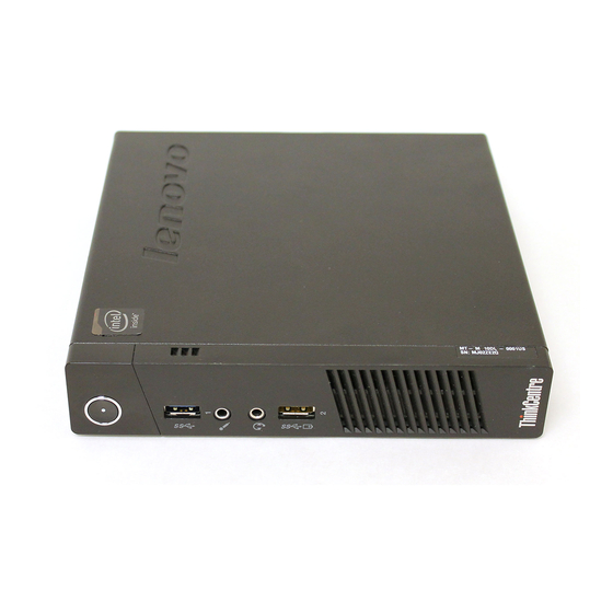
Locating connectors, controls, and indicators on the front of your computer Figure 1 “Front connector, control, and indicator locations” on page 8 shows the locations of the connectors, controls, and indicators on the front of your computer. Figure 1. Front connector, control, and indicator locations Power button Bluetooth activity indicator Wireless activity indicator... -
Page 21: Locating Connectors On The Rear Of Your Computer
• By default, the Always On USB 3.0 connector enables you to charge some mobile digital devices and smartphones when your computer is in sleep or hibernation mode or is powered off. Locating connectors on the rear of your computer Figure 2 “Rear connector locations”... - Page 22 Connector Description DisplayPort connector Used to attach a high-performance monitor, a direct-drive monitor, or other devices that use a DisplayPort connector. Note: The DisplayPort connector is not applicable on some models. If your computer has a graphics card installed, be sure to use a monitor connector on the graphics card.
-
Page 23: Locating Components
Locating components Figure 3 “Component locations” on page 11 shows the locations of the various components in your computer. To remove the computer cover, see “Removing the computer cover” on page 55. Figure 3. Component locations Chapter 1 Product overview... -
Page 24: Locating Parts On The System Board
Computer cover System fan Thermal module Cover presence switch (intrusion switch) Internal speaker Microprocessor Front Wi-Fi antenna Power button board Power cord ac power adapter Memory modules Battery Wi-Fi card module Rear Wi-Fi antenna cable Rear Wi-Fi antenna Hard disk drive assembly (with a hard disk drive or solid-state drive installed) Locating parts on the system board Figure 4 “System board part locations”... -
Page 25: Machine Type And Model Label
Optional USB 2.0 connector Machine type and model label The machine type and model label identifies your computer. When you contact Lenovo for help, the machine type and model information helps support technicians to identify your computer and provide faster service. - Page 26 ThinkCentre M73 User Guide...
-
Page 27: Chapter 2. Using Your Computer
USB key. If your computer does not come with it, contact the Lenovo Customer Support Center to order a recovery disc set or recovery USB key. For a list of Lenovo Support phone numbers, go to http://www.lenovo.com/support/phone. If you cannot find the support telephone number for your country or region, contact your Lenovo reseller. - Page 28 • From the Start screen, do one of the following to navigate to the most recently accessed workspace (application, PC settings, or desktop): – Using a pointing device: Move the pointer to the extreme bottom-left corner of the screen until a small representation of the workspace is displayed;...
-
Page 29: Navigating On Windows 8.1
– Using a touch screen: Swipe in from the left edge of the screen. For information about using other features of the Windows 8 operating system, refer to the Windows help system. For more information, see “Windows help system” on page 125. Navigating on Windows 8.1 To navigate among the desktop, the Start screen, and applications that were opened from the Start screen on the Windows 8.1 operating system, do one of the following:... -
Page 30: Accessing Control Panel On The Windows 8 Or Windows 8.1 Operating System
Note: Only active workspaces that you have accessed during the current Windows session are displayed along the left edge. If you close an active workspace, its representation does not display along the left edge of the screen. 2. Click the representation. –... -
Page 31: Using The Wheel Mouse
• The two Windows logo keys are located beside the Alt key on either side of the spacebar. They feature the Windows logo. On the Windows 7 or Windows 10 operating system, press the Windows key open the Start menu. On the Windows 8 or Windows 8.1 operating system, press the Windows key to switch between the current workspace and the Start screen. -
Page 32: Using Cds And Dvds
• For Windows 7: Click the Start button to open the Start menu, and then click Control Panel. View Control Panel using Large icons or Small icons, and then click Notification Area Icons ➙ Turn system icons on or off. •... -
Page 33: Playing A Cd Or Dvd
Playing a CD or DVD If your computer comes with a DVD drive, you can listen to audio CDs or watch DVD movies. To play a CD or DVD, do the following: 1. Press the Eject/Load button on the DVD drive to open the tray. 2. - Page 34 ThinkCentre M73 User Guide...
-
Page 35: Chapter 3. You And Your Computer
51 to 61 cm (20 to 24 inches), and position it so you can view it without having to twist your body. Also, position other equipment you use regularly, such as the telephone or a mouse, within easy reach. © Copyright Lenovo 2013, 2015... -
Page 36: Glare And Lighting
For more information about power cords, see “Power cords and power adapters” on page vi. Accessibility information Lenovo is committed to providing users who have hearing, vision, and mobility limitations with greater access to information and technology. This section provides information about the ways these users can get the most out of their computer experience. - Page 37 Keyboard shortcut Function Num Lock for five seconds Turn on or turn off Toggle Keys Left Alt+Left Shift+Num Lock Turn on or turn off Mouse Keys Left Alt+Left Shift+PrtScn (or PrtSc) Turn on or turn off High Contrast For more information, go to http://windows.microsoft.com/, and then perform a search using any of the following keywords: keyboard shortcuts, key combinations, shortcut keys.
- Page 38 Using only your voice, you can start programs, open menus, click objects on the screen, dictate text into documents, and write and send e-mails. Everything you do with the keyboard and mouse can be done with only your voice. To use Speech Recognition, do the following: 1.
-
Page 39: Registering Your Computer
Lenovo for help. In addition, some locations offer extended privileges and services to registered users. To register your computer with Lenovo, ensure that your computer is connected to the Internet. Then, go to http://www.lenovo.com/register and follow the instructions on the screen. - Page 40 ThinkCentre M73 User Guide...
-
Page 41: Chapter 4. Security
For more information, see “Selecting or changing the startup device sequence” on page 96. • Startup without keyboard or mouse Your computer is able to log in to the operating system without keyboard or mouse connected. © Copyright Lenovo 2013, 2015... -
Page 42: Attaching A Kensington-Style Cable Lock
The cable lock also locks the buttons used to open the computer cover. This is the same type of lock used with many notebook computers. You can order such a cable lock directly from Lenovo by searching for Kensington at: http://www.lenovo.com/support Figure 6. -
Page 43: Using Fingerprint Authentication
Your computer is preinstalled with an antivirus program to help you guard against, detect, and eliminate viruses. Lenovo provides a full version of antivirus software on your computer with a free 30-day subscription. After 30 days, you must renew the license to continue receiving the antivirus software updates. - Page 44 ThinkCentre M73 User Guide...
-
Page 45: Chapter 5. Installing Or Replacing Hardware
Do not open your computer or attempt any repair before reading and understanding the “Important safety information” on page v. Notes: • Use only computer parts provided by Lenovo. • When installing or replacing an option, use the appropriate instructions in this section along with the instructions that come with the option. -
Page 46: Installing Or Removing The Ac Power Adapter
Installing or removing the ac power adapter Attention: Do not open your computer or attempt any repair before reading and understanding the “Important safety information” on page v. This section provides instructions on how to install or remove the ac power adapter. To install the ac power adapter, connect the ac power adapter to the ac power adapter connector at the rear of your computer and a workable electrical outlet. -
Page 47: Installing Or Removing The Vertical Stand
2. Remove the power cord from the ac power adapter cable loop at the rear of the computer and then disconnect the ac power adapter from the computer. Figure 8. Disconnecting the ac power adapter What to do next: • To work with another piece of hardware, go to the appropriate section. Installing or removing the vertical stand Attention: Do not open your computer or attempt any repair before reading and understanding the “Important safety information”... - Page 48 To install the vertical stand, do the following: 1. Turn off the computer. 2. Align the rear of the computer with the rear of the vertical stand and position the computer on the vertical stand as shown. Figure 9. Installing the vertical stand To remove the vertical stand, do the following: 1.
-
Page 49: Installing Or Removing The Vesa Mount Bracket
2. Lift the computer to remove it from the vertical stand. Figure 10. Removing the computer from the vertical stand Installing or removing the VESA mount bracket Attention: Do not open your computer or attempt any repair before reading and understanding the “Important safety information” on page v. - Page 50 2. Slide the computer into the VESA mount bracket. Figure 11. Installing the VESA mount bracket 3. Install the two screws to secure the VESA mount bracket to the computer. Figure 12. Installing the screws that secure the VESA mount bracket To remove the VESA mount bracket, do the following: 1.
-
Page 51: Installing Or Removing The Ac Power Adapter Bracket
2. Remove the two screws that secure the VESA mount bracket to the computer. Figure 13. Removing the screws that secure the VESA mount bracket 3. Slide the computer from the front of the VESA mount bracket to remove the VESA mount bracket from the computer. - Page 52 1. Turn off the computer and disconnect all power cords from electrical outlets. 2. Pull the tab and then slide the ac power adapter bracket as shown to remove it from the VESA mount bracket. Figure 15. Removing the ac power adapter bracket ThinkCentre M73 User Guide...
-
Page 53: Replacing The Optical Drive
To install the ac power adapter bracket to the VESA mount bracket, align the two tabs on the ac power adapter bracket with the slots in the VESA mount bracket, and then slide the ac power adapter bracket as shown to install it on the VESA mount bracket. Figure 16. - Page 54 3. Remove the screw that secures the optical drive box on the VESA mount bracket and then slide the optical drive box to remove it from the VESA mount bracket. Figure 17. Removing the optical drive box 4. Remove the screw that secures the optical drive in the optical drive box. Use the screwdriver to slide the optical drive forward and then remove the optical drive from the optical drive box.
- Page 55 5. Remove the two screws that secure the optical drive metal plate and then remove the metal plate from the optical drive. Figure 19. Removing the optical drive metal plate 6. Align the two screw holes in the optical drive metal plate with the corresponding holes in the new optical drive and then install the two screws to secure the metal plate on the new optical drive.
- Page 56 7. Slide the new optical drive into the optical drive box until it snaps into position. Figure 21. Installing the optical drive into the optical drive box 8. Install the screw that secures the optical drive in the optical drive box. Figure 22.
- Page 57 9. Align the screw holes in the optical drive box with the two screws on the VESA mount bracket and then slide the optical drive box to install it on the VESA mount bracket. Figure 23. Installing the optical drive box Chapter 5 Installing or replacing hardware...
-
Page 58: Replacing The Secondary Hard Disk Drive
10. Install the screw that secures the optical drive box on the VESA mount bracket. Figure 24. Installing the screw that secures the optical drive box 11. Connect the optical drive cable to a USB connector on the computer. See “Locating connectors on the rear of your computer”... - Page 59 3. Remove the screw that secures the optical drive box on the VESA mount bracket and then slide the optical drive box as shown to remove it from the VESA mount bracket. Figure 25. Removing the optical drive box 4. Slide the release button on the optical drive box and then remove the secondary hard disk drive adapter from the optical drive box.
- Page 60 5. Flex the sides of the hard disk drive adapter bracket and then pivot the hard disk drive adapter to remove the adapter from the adapter bracket. Figure 27. Removing the hard disk drive adapter from the adapter bracket 6. To remove the hard disk drive from the adapter, lift the adapter retaining latch. Slide the hard disk drive towards the retaining latch and then lift the hard disk drive out of the adapter.
- Page 61 8. Install the new hard disk drive into the adapter as shown. Then, lower the adapter retaining latch until it snaps into position. Figure 30. Installing a new hard disk drive into the adapter 9. Position the adapter into the adapter bracket and then pivot the adapter downward until it snaps into position.
- Page 62 10. Slide the adapter bracket into the optical drive box until it snaps into position. Figure 32. Installing the adapter bracket into the optical drive box ThinkCentre M73 User Guide...
- Page 63 11. Align the screw holes in the optical drive box with the two screws on the VESA mount bracket and then slide the optical drive box to install it on the VESA mount bracket. Figure 33. Installing the optical drive box Chapter 5 Installing or replacing hardware...
-
Page 64: Installing Or Removing The I/O Box
12. Install the screw that secures the optical drive box on the VESA mount bracket. Figure 34. Installing the screw that secures the optical drive box 13. Connect the secondary hard disk drive cable to a USB connector on the computer. See “Locating connectors on the rear of your computer”... - Page 65 3. Remove the screw that secures the I/O box on the VESA mount bracket and then slide the I/O box as shown to remove it from the VESA mount bracket. Figure 35. Removing the I/O box To install the I/O box, do the following: 1.
- Page 66 2. Align the two holes in the I/O box with the two screws on the VESA mount bracket and then slide the I/O box as shown to install it on the VESA mount bracket. Figure 36. Installing the I/O box ThinkCentre M73 User Guide...
-
Page 67: Removing The Computer Cover
3. Install the screw to secure the I/O box on the VESA mount bracket. Figure 37. Installing the screw to secure the I/O box 4. Connect the I/O box cable to a USB connector on the rear of your computer. See “Locating connectors on the rear of your computer”... - Page 68 5. Remove the screw that secures the computer cover. Figure 38. Removing the computer cover screw ThinkCentre M73 User Guide...
-
Page 69: Installing Or Removing The Hard Disk Drive Assembly
6. Slide the computer cover to the front of the computer a small amount. Then, lift the computer cover to remove it from the computer. Figure 39. Removing the computer cover Installing or removing the hard disk drive assembly Attention: Do not open your computer or attempt any repair before reading and understanding the “Important safety information”... - Page 70 5. Remove the two screws that secure the hard disk drive assembly. Slide the hard disk drive assembly as shown, and then lift the hard disk drive assembly to remove it from the computer. Figure 40. Removing the hard disk drive assembly To install the hard disk drive assembly, do the following: 1.
-
Page 71: Installing Or Replacing A Memory Module
2. Install the two screws to secure the hard disk drive assembly. Figure 42. Installing the screws to secure the hard disk drive assembly 3. Connect the signal cable and the power cable to the hard disk drive. What to do next: •... -
Page 72: Replacing The Battery
5. If you are replacing an old memory module, open the retaining clips and gently pull the memory module out of the memory slot. Figure 43. Removing the memory module 6. Insert the notched end of the new memory module into the slot . - Page 73 Your computer has a special type of memory that maintains the date, time, and settings for built-in features, such as parallel-connector assignments (configuration). A battery keeps this information active when you turn off the computer. The battery normally requires no charging or maintenance throughout its life; however, no battery lasts forever.
-
Page 74: Replacing The Power Button Board
10. Use the Setup Utility program to set the date, time, and any passwords. See Chapter 7 “Using the Setup Utility program” on page 93. Replacing the Power button board Attention: Do not open your computer or attempt any repair before reading and understanding the “Important safety information” on page v. -
Page 75: Replacing The Wi-Fi Card Module
7. Align the hole in the new Power button board with the tab on the computer and position the new Power button board in the computer. Then, install the screw to secure the new Power button board on the chassis. Figure 48. - Page 76 3. Remove the hard disk drive assembly. See “Installing or removing the hard disk drive assembly” on page 57. 4. Locate the Wi-Fi card module in the computer. See “Locating components” on page 11. 5. Disconnect the Wi-Fi antenna cables from the Wi-Fi card module. Figure 49.
-
Page 77: Installing Or Removing The Front Wi-Fi Antenna
What to do next: • To work with another piece of hardware, go to the appropriate section. • To complete the installation or replacement, go to “Completing the parts replacement” on page 80. Installing or removing the front Wi-Fi antenna Attention: Do not open your computer or attempt any repair before reading and understanding the “Important safety information”... - Page 78 6. Route the front Wi-Fi antenna cable through the five hooks in the hard disk drive bracket as shown. Figure 55. Routing the front Wi-Fi antenna cable 7. Reinstall the hard disk drive assembly without connecting the signal cable and power cable. See “Installing or removing the hard disk drive assembly”...
-
Page 79: Installing Or Removing The Rear Wi-Fi Antenna
5. Release the front Wi-Fi antenna cable from the hooks on the hard disk drive bracket. Then, unstick the front Wi-Fi antenna from the hard disk drive bracket. Figure 57. Removing the front Wi-Fi antenna cable What to do next: •... - Page 80 3. Adjust the angle of the rear antenna to lower the risk of breaking the antenna by accident. Figure 58. Installing the rear Wi-Fi antenna To remove the rear Wi-Fi antenna, do the following: 1. Turn off the computer and disconnect all power cords from electrical outlets. 2.
-
Page 81: Replacing The Internal Speaker
Replacing the internal speaker Attention: Do not open your computer or attempt any repair before reading and understanding the “Important safety information” on page v. This section provides instructions on how to replace the internal speaker. To replace the internal speaker, do the following: 1. - Page 82 7. Press the tab that secures the internal speaker as shown and then lift the internal speaker out of the internal speaker holder. Figure 61. Removing the internal speaker 8. Press the tab as shown and insert the new internal speaker into the internal speaker holder until the new internal speaker snaps into position and is secured by the tab Figure 62.
-
Page 83: Replacing The Cover Presence Switch
9. Secure the cable of the new internal speaker in the retaining clip on the side of the thermal module bracket. Figure 63. Securing the internal speaker cable 10. Connect the cable of the new internal speaker to the internal speaker connector on the system board. See “Locating parts on the system board”... - Page 84 5. Pull the cover presence switch to remove it from the heat sink bracket. Figure 64. Removing the cover presence switch 6. Attach the new cover presence switch to the thermal module. Figure 65. Installing the cover presence switch 7. Connect the cable of the new cover presence switch to the cover presence switch connector on the system board.
-
Page 85: Replacing The System Fan
What to do next: • To work with another piece of hardware, go to the appropriate section. • To complete the installation or replacement, go to “Completing the parts replacement” on page 80. Replacing the system fan Attention: Do not open your computer or attempt any repair before reading and understanding the “Important safety information” on page v. - Page 86 5. Remove the three screws that secure the system fan to the thermal module, and then lift the system fan to remove it from the computer. Figure 66. Removing the system fan ThinkCentre M73 User Guide...
-
Page 87: Replacing The Thermal Module
6. Position the new system fan on the chassis so that the three screw holes in the new system fan are aligned with the screw posts on the thermal module. Then, install the three screws to secure the system fan to the computer. Figure 67. - Page 88 3. Locate the thermal module in the computer. See “Locating components” on page 11. 4. Remove the internal speaker. See “Replacing the internal speaker” on page 69. 5. Remove the cover presence switch. See “Replacing the cover presence switch” on page 71. 6.
-
Page 89: Replacing The Microprocessor
8. install the new thermal module into the chassis as shown. Ensure that the four screws on the new thermal module are aligned with corresponding holes in the system board. Figure 69. Positioning the new thermal module 9. Follow the clockwise sequence of , and to install the four screws to secure the new thermal module. - Page 90 4. Lift the small handle and open the retainer to access the microprocessor Figure 70. Accessing the microprocessor 5. Lift the microprocessor straight up and out of the microprocessor socket. Notes: • Your microprocessor and socket might look different from the one illustrated. •...
-
Page 91: Replacing The Keyboard Or Mouse
8. Note the orientation of the new microprocessor. Hold the new microprocessor by its edges and align the notches on it with the tabs in the microprocessor socket. Then, carefully lower the new microprocessor straight down into the microprocessor socket. Note: The small triangle on one corner of the new microprocessor is the microprocessor orientation indicator. -
Page 92: Completing The Parts Replacement
2. Connect a new keyboard or mouse to one of the USB connectors on the computer. Depending on where you want to connect the new keyboard or mouse, see “Locating connectors, controls, and indicators on the front of your computer” on page 8 or “Locating connectors on the rear of your computer” on page 9. Figure 73. - Page 93 3. Position the computer cover on the chassis and then push the cover to the rear of the computer until it snaps into position. Figure 74. Installing the computer cover Chapter 5 Installing or replacing hardware...
-
Page 94: Obtaining Device Drivers
7. To update your configuration, refer to Chapter 7 “Using the Setup Utility program” on page 93. Note: In most areas of the world, Lenovo requires the return of the defective Customer Replaceable Unit (CRU). Information about this will come with the CRU or will come a few days after the CRU arrives. -
Page 95: Chapter 6. Recovery Information
Recovery program or the Product Recovery program installed. If the Enhanced Backup and Restore icon in the Lenovo ThinkVantage Tools program is dimmed, it indicates that you need to install the Rescue and Recovery program manually before enabling its features. To install the Rescue and Recovery program, do the following: a. -
Page 96: Performing Backup And Recovery Operations
Note: On the Windows 7 operating system, you can create recovery media using discs or external USB storage devices. To create recovery media on the Windows 7 operating system, click Start ➙ All Programs ➙ Lenovo ThinkVantage Tools ➙ Factory Recovery Disks. Then, follow the instructions on the screen. -
Page 97: Using The Rescue And Recovery Workspace
1. From the Windows desktop, click Start ➙ All Programs ➙ Lenovo ThinkVantage Tools ➙ Enhanced Backup and Restore. The Rescue and Recovery program opens. 2. In the Rescue and Recovery main window, click the Launch advanced Rescue and Recovery arrow. -
Page 98: Creating And Using A Rescue Medium
This section provides instructions on how to create a rescue medium. To create a rescue medium on the Windows 7 operating system, do the following: 1. From the Windows desktop, click Start ➙ All Programs ➙ Lenovo ThinkVantage Tools ➙ Enhanced Backup and Restore. The Rescue and Recovery program opens. -
Page 99: Reinstalling Preinstalled Applications And Device Drivers
Reinstalling preinstalled applications This section provides instructions on how to reinstall preinstalled applications. To reinstall the selected applications preinstalled on your Lenovo computer, do the following: 1. Turn on the computer. 2. Go to the C:\SWTOOLS directory. 3. Open the apps folder. Within the apps folder, there are several subfolders named for various applications installed in your computer. -
Page 100: Reinstalling Software Programs
• To reinstall most commercially available programs in your system, see Microsoft Windows help system for more information. • To reinstall selected application programs that came preinstalled from Lenovo, do the following: 1. Turn on the computer. 2. Go to the C:\SWTOOLS directory. -
Page 101: Recovery Information For The Windows 8 Or Windows 8.1 Operating System
Recovery information for the Windows 8 or Windows 8.1 operating system This section provides information about the recovery solutions provided on computers preinstalled with the Windows 8 or Windows 8.1 operating system. Refreshing your computer If your computer does not perform well and the problem might be caused by a recently installed program, you can refresh your computer without losing your personal files or changing your settings. -
Page 102: Recovering Your Operating System If Windows 8 Or Windows 8.1 Fails To Start
1. Move the pointer to the top-right or bottom-right corner of the screen to display the charms. Click Settings ➙ Change PC settings ➙ General. 2. In the Advanced startup section, click Restart now ➙ Troubleshoot ➙ Advanced options. 3. Restart your computer following the instructions on the screen. •... - Page 103 Note: To create a recovery medium, see “Good maintenance practices” on page 103. • Use the recovery USB key provided by Lenovo to restore the entire storage drive to the factory-default settings. – If your computer comes with the recovery USB key, follow the instructions shipped with the USB key.
- Page 104 ThinkCentre M73 User Guide...
-
Page 105: Chapter 7. Using The Setup Utility Program
You can use either the keyboard or the mouse to navigate through BIOS menu choices. The keys used to perform various tasks are displayed at the bottom of each screen. Using BIOS passwords By using the Setup Utility program, you can set passwords to prevent unauthorized access to your computer and data. © Copyright Lenovo 2013, 2015... -
Page 106: Password Considerations
You do not have to set any passwords to use your computer. However, using passwords improves computing security. If you decide to set any passwords, read the following sections. Password considerations A password can be any combination of up to 64 alphabetic and numeric characters. For security reasons, it is recommended to use a strong password that cannot be easily compromised. -
Page 107: Erasing Lost Or Forgotten Passwords (Clearing Cmos)
Note: The USB 2.0 connector (USB port 3) on the rear of your computer supports the smart power on feature. If you connect a Lenovo-recommended USB 1.1 keyboard to this connector, you can power on the computer or wake it up from S4 hibernation mode by pressing Alt+P on the keyboard. Ensure that you use a Lenovo-recommended keyboard that supports the smart power on feature. -
Page 108: Selecting A Startup Device
98. Enabling ErP LPS compliance mode Lenovo computers meet the eco-design requirements of the ErP Lot 3 regulation. For more information, go http://www.lenovo.com/ecodeclaration You can enable ErP LPS compliance mode in the Setup Utility program to reduce the consumption of electricity when your computer is off or in sleep mode. -
Page 109: Ice Performance Mode
• Pressing the power switch • Enabling the wake up on alarm feature The wake up on alarm feature enables your computer to wake up at a set time. To enable the wake up on alarm feature, do the following: 1. -
Page 110: Exiting The Setup Utility Program
After enabling the ICE thermal alert function, when critical thermal situations occur, such as malfunctioning fans, abnormally high temperature, and poor cooling performances, an alert log will be written into the Windows system log. The alert log can help you identify the thermal problems. To configure the ICE thermal alert function, do the following: 1. -
Page 111: Chapter 8. Updating System Programs
Utility program by starting your computer with a system-program-update disc or running a special update program from your operating system. Lenovo might make changes and enhancements to the POST and BIOS. When updates are released, they are available as downloadable files on the Lenovo Web site at http://www.lenovo.com. Instructions for using the POST and BIOS updates are available in a TXT file that is included with the update files. - Page 112 4. Remove any cables that impede access to the Clear CMOS /Recovery jumper. 5. Move the jumper from the standard position (pin 1 and pin 2) to the maintenance position (pin 2 and pin 3). 6. Reconnect any cables that were disconnected and reinstall the PCI card if removed. 7.
-
Page 113: Chapter 9. Preventing Problems
• Download the device drivers that are preinstalled on your computer. Go to http://www.lenovo.com/drivers. • Use the Lenovo program or Windows Update. See “Getting the latest system updates” on page 101. Note: The device drivers provided by Windows Update might not be tested by Lenovo. It is recommended that you get device drivers from Lenovo. -
Page 114: Cleaning And Maintenance
Cleaning and maintenance With appropriate care and maintenance your computer will serve you reliably. The following topics offer information to help you keep your computer in top working order. • “Basics” on page 102 • “Cleaning your computer” on page 102 –... -
Page 115: Good Maintenance Practices
Optical mouse This section provides instructions on how to clean an optical mouse. An optical mouse uses a light-emitting diode (LED) and an optical sensor to navigate the pointer. If the pointer on the screen does not move smoothly with the optical mouse, you might need to clean the mouse. To clean an optical mouse, do the following: 1. -
Page 116: Moving Your Computer
The cause of a problem might be change in hardware, change in software, or any other actions that might have taken place. A log book can help you or a Lenovo technician determine the cause of a problem. • Back up your data on the storage drive regularly. You can restore the storage drive from a backup. - Page 117 6. Note where any remaining cables are attached to the computer; then, remove them. 7. If you saved the original shipping cartons and packing materials, use them to pack the units. If you are using different cartons, cushion the units to avoid damage. Chapter 9 Preventing problems...
- Page 118 ThinkCentre M73 User Guide...
-
Page 119: Chapter 10. Troubleshooting And Diagnostics
Note: If you cannot correct the problem, have the computer serviced. For a list of service and support telephone numbers, refer to the Safety, Warranty, and Setup Guide that comes with your computer or go to the Lenovo Support Web site at http://www.lenovo.com/support/phone. Symptom... -
Page 120: Troubleshooting Procedure
See Chapter 11 “Getting information, help, and service” on page 125 for more information. • If you are unable to run the diagnostic program, contact the Lenovo Customer Support Center. See Chapter 11 “Getting information, help, and service” on page 125 for more information. -
Page 121: Troubleshooting
Troubleshooting Use the troubleshooting information to find solutions to problems that have definite symptoms. If the symptom your computer is experiencing occurred immediately after you installed a new hardware option or new software, do the following before referring to the troubleshooting information: 1. -
Page 122: Cd Problems
Refer to the documentation that comes with the application or game for instructions on setting sound-card settings. • If these actions do not correct the problem, run the Lenovo Solution Center program. If you need technical assistance, see Chapter 11 “Getting information, help, and service” on page 125. -
Page 123: Dvd Problems
Note that on some models the startup sequence is permanently set and cannot be changed. If these actions do not correct the problem, run the Lenovo Solution Center program. If you need technical assistance, see Chapter 11 “Getting information, help, and service” on page 125. - Page 124 • Close any open files, turn off the computer, and then restart the computer. • Try a lower screen resolution or color depth. If these actions do not correct the problem, run the Lenovo Solution Center program. If you need technical assistance, see Chapter 11 “Getting information, help, and service” on page 125.
-
Page 125: Intermittent Problems
• On computers that have a CD-ROM or CD-RW drive in addition to a DVD-ROM drive, make sure that the DVD disc is in the drive labeled “DVD”. If these actions do not correct the problem, run the Lenovo Solution Center program. If you need technical assistance, see Chapter 11 “Getting information, help, and service” on page 125. - Page 126 See “Enabling or disabling a device” on page 95. If these actions do not correct the problem, run the Lenovo Solution Center program. If you need technical assistance, see Chapter 11 “Getting information, help, and service” on page 125.
-
Page 127: Monitor Problems
If these actions do not correct the problem, run the Lenovo Solution Center program. If you need technical assistance, see Chapter 11 “Getting information, help, and service” on page 125. -
Page 128: Networking Problems
If these actions do not correct the problem, run the Lenovo Solution Center program. If you need technical assistance, see Chapter 11 “Getting information, help, and service” on page 125. The image appears to be flickering Solutions: • The screen might be affected by interference from nearby equipment. Magnetic fields around other devices, such as transformers, appliances, fluorescent lights, and other monitors might be causing the problem. - Page 129 • “If your computer is a Gigabit Ethernet model and you use a speed of 1000 Mbps, the connection fails or errors occur” on page 118 • “If your computer is a Gigabit Ethernet model, it cannot connect to the network at 1000 Mbps. Instead, it connects at 100 Mbps”...
- Page 130 Action: The network driver files may be corrupt or missing. Update the driver by referring to the “Solution” description for the procedure to make sure that the correct device driver is installed. The Wake on LAN feature is not working Symptom: The Wake on LAN (WOL) feature is not working.
-
Page 131: Option Problems
If these actions do not correct the problem, run the Lenovo Solution Center program. If you need technical assistance, see Chapter 11 “Getting information, help, and service” on page 125. -
Page 132: Performance And Lockup Problems
• Verify that the option and any required device drivers are installed correctly. If these actions do not correct the problem, run the Lenovo Solution Center program. If you need technical assistance, see Chapter 11 “Getting information, help, and service” on page 125. -
Page 133: Printer Problems
125. For step-by-step instructions on installing memory, see “Installing or replacing a memory module” on page 59. If these actions do not correct the problem, run the Lenovo Solution Center program. If you need technical assistance, see Chapter 11 “Getting information, help, and service” on page 125. -
Page 134: Serial Connector Problems
• Make sure that the serial-connector adapter, if you added one, is properly installed and firmly seated. If these actions do not correct the problem, run the Lenovo Solution Center program. If you need technical assistance, see Chapter 11 “Getting information, help, and service” on page 125. -
Page 135: Usb Problems
• Reset the device by detaching and reattaching the USB connector. If these actions do not correct the problem, run the Lenovo Solution Center program to test the USB connector. If the USB device came with its own diagnostics, run those diagnostics against the USB device. -
Page 136: Lenovo Solution Center
Note: If you are unable to isolate and repair the problem yourself after running the program, save and print the log files. You will need the log files when you speak to a Lenovo technical support representative. ThinkCentre M73 User Guide... -
Page 137: Chapter 11. Getting Information, Help, And Service
Read and understand all safety information before using this product. Lenovo Web site The Lenovo Web site (http://www.lenovo.com) provides up-to-date information and services to help you buy, upgrade, and maintain your computer. You can also do the following: •... -
Page 138: Lenovo Support Web Site
Most computers come with a diagnostic program that help you identify hardware problems. You can also get the latest technical information and download device drivers and updates from Lenovo Support Web site at: http://www.lenovo.com/support... -
Page 139: Using Other Services
Service availability and service name might vary by country or region. For more information about these services, go to the Lenovo Web site at: http://www.lenovo.com... - Page 140 ThinkCentre M73 User Guide...
-
Page 141: Appendix A. Notices
Lenovo representative for information on the products and services currently available in your area. Any reference to a Lenovo product, program, or service is not intended to state or imply that only that Lenovo product, program, or service may be used. Any functionally equivalent product, program, or service that does not infringe any Lenovo intellectual property right may be used instead. -
Page 142: Trademarks
Trademarks The following terms are trademarks of Lenovo in the United States, other countries, or both: Lenovo Rescue and Recovery The Lenovo logo The ThinkCentre logo ThinkCentre ThinkVantage Microsoft, Windows, and Windows Media are trademarks of the Microsoft group of companies. -
Page 143: Appendix B. Regulatory Information
• Consult an authorized dealer or service representative for help. Lenovo is not responsible for any radio or television interference caused by using other than specified or recommended cables and connectors or by unauthorized changes or modifications to this equipment. - Page 144 Geräte der Klasse B. Dieses Gerät ist berechtigt, in Übereinstimmung mit dem Deutschen EMVG das EG-Konformitätszeichen - CE - zu führen. Verantwortlich für die Konformitätserklärung nach Paragraf 5 des EMVG ist die Lenovo (Deutschland) GmbH, Gropiusplatz 10, D-70563 Stuttgart. Informationen in Hinsicht EMVG Paragraf 4 Abs. (1) 4: Das Gerät erfüllt die Schutzanforderungen nach EN 55024 und EN 55022 Klasse B.
-
Page 145: Eurasian Compliance Mark
All regulatory notices are available on the Lenovo Support Web site in electronic format. To access electronic copies of the documentation, go to http://www.lenovo.com/support and click User Guides & Manuals. - Page 146 ThinkCentre M73 User Guide...
-
Page 147: Appendix C. Weee And Recycling Information
Collecting and recycling a disused Lenovo computer or monitor If you are a company employee and need to dispose of a Lenovo computer or monitor that is the property of the company, you must do so in accordance with the Law for Promotion of Effective Utilization of Resources. -
Page 148: Recycling Information For Brazil
If you want to replace it with a new one, contact your place of purchase or ask for a repair service provided by Lenovo. If you have replaced it by yourself and want to dispose of the disused lithium battery, insulate it with vinyl tape, contact your place of purchase, and follow their instructions. - Page 149 Customer participation is important to minimize any potential effects of batteries and accumulators on the environment and human health due to the potential presence of hazardous substances. For proper collection and treatment, go to: http://www.lenovo.com/recycling Appendix C. WEEE and recycling information...
- Page 150 ThinkCentre M73 User Guide...
-
Page 151: Appendix D. Restriction Of Hazardous Substances Directive (Rohs)
(RoHS) European Union RoHS Lenovo products sold in the European Union, on or after 3 January 2013 meet the requirements of Directive 2011/65/EU on the restriction of the use of certain hazardous substances in electrical and electronic equipment (“RoHS recast” or “RoHS 2”). -
Page 152: Ukraine Rohs
Ukraine RoHS India RoHS RoHS compliant as per E-Waste (Management & Handling) Rules, 2011. ThinkCentre M73 User Guide... -
Page 153: Appendix E. China Energy Label
Appendix E. China Energy Label © Copyright Lenovo 2013, 2015... - Page 154 ThinkCentre M73 User Guide...
-
Page 155: Appendix F. Energy Star Model Information
For more information about ENERGY STAR, go to: http://www.energystar.gov Lenovo encourages you to make efficient use of energy an integral part of your day-to-day operations. To help in this endeavor, set the following power-management features to take effect when your computer has been inactive for a specified duration: Table 1. - Page 156 3. Follow the instructions on the screen. ThinkCentre M73 User Guide...
-
Page 157: Index
Description VESA mount bracket device drivers internal drives devices, handling static-sensitive internal speaker, replacing diagnostics program, using diagnostics, troubleshooting DisplayPort connector documentation, using drivers, device Kensington-style cable lock © Copyright Lenovo 2013, 2015... - Page 158 Lenovo Solution Center removing computer cover locating components replacing battery cover presence switch hard disk drive media, creating and using recovery media heat sink and fan assembly...
- Page 159 Setup Utility vertical stand installing or removing VESA mount bracket, installing or removing VGA monitor connector video subsystem viewing and changing settings warranty information WiFi card module, replacing workspace, backup and recovery © Copyright Lenovo 2013, 2015...
- Page 160 ThinkCentre M73 User Guide...
Need help?
Do you have a question about the ThinkCentre M73 10DL and is the answer not in the manual?
Questions and answers