Mitsubishi Electric MS-GA50VB Service Manual
Split-type
Hide thumbs
Also See for MS-GA50VB:
- Operating instructions manual (13 pages) ,
- Operating instructions manual (24 pages) ,
- Service manual (28 pages)
Table of Contents
Advertisement
SPLIT-TYPE AIR CONDITIONERS
INDOOR UNIT
SERVICE MANUAL
Models
MS-GA50VB -
MS-GA60VB -
MS-GA80VB -
NOTE:
This service manual describes technical data of the indoor units.
RoHS compliant products have <G> mark on the spec name plate.
For servicing of RoHS compliant products, refer to the RoHS PARTS LIST (RoHS compliant).
Revision D :
• Parts numbers of indoor fan motor and motor band have been
changed.
• Some descriptions have been modified.
Please void OB369 REVISED EDITION-C.
E1
E1
E1
CONTENTS
1. TECHNICAL CHANGES ····································2
2. PART NAMES AND FUNCTIONS······················3
3. SPECIFICATION·················································5
4. NOISE CRITERIA CURVES ·······························6
5. OUTLINES AND DIMENSIONS ·························7
6. WIRING DIAGRAM ············································8
7. REFRIGERANT SYSTEM DIAGRAM ················9
8. SERVICE FUNCTIONS ····································10
9. TROUBLESHOOTING······································12
10. DISASSEMBLY INSTRUCTIONS·····················21
11. PARTS LIST······················································23
12. RoHS PARTS LIST···········································25
13. OPTIONAL PARTS···········································27
No. OB369
REVISED EDITION-D
Outdoor unit service manual
MU-GA•VB Series (OB370)
Advertisement
Table of Contents
Troubleshooting

Related Manuals for Mitsubishi Electric MS-GA50VB


Summary of Contents for Mitsubishi Electric MS-GA50VB
-
Page 1: Table Of Contents
• Some descriptions have been modified. Please void OB369 REVISED EDITION-C. INDOOR UNIT No. OB369 SERVICE MANUAL REVISED EDITION-D Models MS-GA50VB - MS-GA60VB - MS-GA80VB - Outdoor unit service manual MU-GA•VB Series (OB370) CONTENTS 1. TECHNICAL CHANGES ····································2 2. PART NAMES AND FUNCTIONS······················3 3. -
Page 2: Technical Changes
Revision D : • Parts numbers of indoor fan motor and motor band have been changed. • Some descriptions have been modified. TECHNICAL CHANGES MS-A18WV - MS-GA50VB - MS-A24WV - MS-GA60VB - MS-A30WV - MS-GA80VB - 1. Model name has been changed. -
Page 3: Part Names And Functions
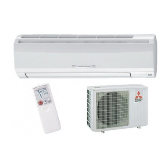
PART NAMES AND FUNCTIONS MS-GA50VB MS-GA60VB Air cleaning filter (option) Grille (White bellows type) MS-GA80VB Air inlet To breaker Front panel Power supply cord Catechin air filter Catechin air filter Remote control receiving section Vertical vanes Horizontal vane Remote controller... -
Page 4: Remote Controller
REMOTE CONTROLLER MS-GA50VB MS-GA60VB MS-GA80VB Signal transmitting section Operation display section OPERATE/ STOP (ON/ OFF) button ON/OFF WARM COOL TEMPERATURE buttons Indication of remote controller model is on back. Open the front lid. CLOCK ON/OFF WARM COOL VANE button FAN SPEED CONTROL button... -
Page 5: Specification
SPECIFICATION Indoor model MS-GA50VB MS-GA60VB Cooling Function Cooling Single phase Single phase Power supply 230V, 50Hz 230V, 50Hz Capacity Air flow(High/Med./Low) K /h 768/642/528 768/672/588 Breaker capacity Running current 0.30 0.30 Power input Power factor Fan motor current 0.30 0.30... -
Page 6: Noise Criteria Curves
NOISE CRITERIA CURVES MS-GA50VB MS-GA60VB FAN SPEED SPL(dB(A)) LINE FAN SPEED SPL(dB(A)) LINE High High Test conditions, Test conditions, Cooling : Dry-bulb temperature 27: Wet-bulb temperature 19: Cooling : Dry-bulb temperature 27: Wet-bulb temperature 19: NC-70 NC-70 NC-60 NC-60 NC-50... -
Page 7: Outlines And Dimensions
OUTLINES AND DIMENSIONS MS-GA50VB Unit: mm MS-GA60VB MS-GA80VB Installation plate Indoor unit 1068 414.5 414.5 Wall hole [75 Liquid line [ 6.35- 0.5m 1100 Air in Installation plate Gas line [ 12-0.43m Insulation [ 50 O.D [ 32 I.D for MS-GA50/60VB Liquid line [ 9.52- 0.5m... -
Page 8: Wiring Diagram
WIRING DIAGRAM MS-GA50VB MS-GA60VB TO OUTDOOR UNIT CN202 CONNECTING HIC1 RT12 CN112 CN201 NR11 SR141 TAB12 POWER SUPPLY CN211 CORD ELECTRONIC CONTROL ~/N 230V RT11 P. C. BOARD 50Hz CIRCUIT DISPLAY RECEIVER BREAKER P. C. BOARD P. C. BOARD REMOTE... -
Page 9: Refrigerant System Diagram
REFRIGERANT SYSTEM DIAGRAM MS-GA50VB MS-GA60VB Unit:mm Refrigerant pipe [15.88 Refrigerant pipe [12.7 (with heat insulator) (with heat insulator) Indoor coil Indoor coil thermistor Indoor Indoor thermistor RT12 RT12 heat heat exchanger exchanger Distributor Distributor Flared connection Flared connection Room temperature... -
Page 10: Service Functions
SERVICE FUNCTIONS MS-GA50VB MS-GA60VB MS-GA80VB 8-1. TIMER SHORT MODE For service, set time can be shortened by short circuit of JPG and JPS on the electronic control P.C. board. The time will be shortened as follows. (Refer to 9-6.) Set time : 1 minute... - Page 11 8-3. AUTO RESTART FUNCTION When the indoor unit is controlled with the remote controller, the operation mode, set temperature, and the fan speed are memorized by the indoor electronic control P.C. board. The “AUTO RESTART FUNCTION” sets to work the moment power has restored after power failure.
-
Page 12: Troubleshooting
TROUBLESHOOTING MS-GA50VB MS-GA60VB MS-GA80VB 9-1. Cautions on troubleshooting 1. Before troubleshooting, check the following: (1) Check the power supply voltage. (2) Check the indoor/outdoor connecting wire for mis-wiring. 2. Take care the following during servicing. (1) Before servicing the air conditioner, be sure to turn OFF the main unit first with the remote controller, and then after confirming the horizontal vane is closed, turn OFF the breaker and / or disconnect the power plug. - Page 13 9-2. Instruction of troubleshooting Start Indoor unit Indoor unit Indoor unit operates. OPERATION INDICATOR operates. does not receive Outdoor unit lamp on the indoor unit is Outdoor unit the signal from does not operate flashing on and off. does not remote controller.
- Page 14 9-3. Troubleshooting check table • The following indication applies regardless of shape of the indicator. Operation Indicator Lighted Not lighted · Flashing of the OPERATION INDICATOR lamp (on the left-hand side) indicates possible abnormalities. · The OPERATION INDICATOR lamp (on the left-hand side) is lighted during normal operation. Before taking measures, make sure that the symptom reappears, for accurate troubleshooting.
- Page 15 9-4. Trouble criterion of main parts MS-GA50VB MS-GA60VB MS-GA80VB Part name Check method and criterion Figure Room temperature Measure the resistance with a tester. (Part temperature 10˚C ~ 30˚C) thermistor(RT11) Indoor coil thermistor Refer to 9-6."Test point diagram and voltage", (RT12(main), RT13(sub)) "Indoor electronic control P.C.
-
Page 16: Troubleshooting Flow
9-5. Troubleshooting flow When OPERATION INDICATOR lamp flashes 3-time. Indoor fan motor does not operate. Check of indoor fan motor Turn OFF the power supply. Check connector CN211 visually. Is soldered point of the connector Are lead wires connected? Resolder it. correctly soldered? Reconnect the lead wires. - Page 17 The unit does not operate with the remote controller. Also, the OPERATION INDICATOR lamp does not light up by pressing the EMERGENCY OPERATION switch. Check of indoor electronic control P.C. board Check the both “parts side” and “pattern Varistor (NR11) side”...
- Page 18 When OPERATION INDICATOR lamp flashes ON and OFF in every 0.5-second. Outdoor unit does not operate. How to check mis-wiring MS-GA80VB w Short circuit of JPG and JPS on the indoor electronic control P.C. board enables self -check to be displayed in 3 seconds. Start •...
- Page 19 9-6. Test point diagram and voltage w There are 2 types of electronic control P.C. boards MS-GA50VB MS-GA60VB MS-GA80VB (TYPE1/TYPE2). Indoor electronic control P.C. board They are both compatible with MS-GA50/60/80VB. TYPE 1 Fan motor power supply (CN211) Power supply input...
- Page 20 MS-GA50VB MS-GA60VB MS-GA80VB Indoor electronic control P.C. board TYPE 2 Fan motor power supply (CN211) Power supply input 230 VAC Fuse (F11) 5 VDC Room temperature thermistor (RT11) R132 Indoor coil thermistor (RT12 (main) MS-GA80VB Indoor coil thermistor (RT13 (sub)
-
Page 21: Disassembly Instructions
Locking lever lever. Connector 10-1. MS-GA50VB MS-GA60VB MS-GA80VB NOTE: Turn OFF power supply before disassembly. OPERATING PROCEDURE PHOTOS 1. Removing the front panel Photo 1 (1) Remove the screw caps of the front panel. - Page 22 OPERATING PROCEDURE PHOTOS Photo 3 3. Removing the electrical box Screws of the earth wire (1) Remove the front panel. (Refer to 1.) (2) Remove the electrical cover. (Refer to 2.) (3) Disconnect the connector of the indoor coil thermistor. (4) Disconnect the motor connector (CN211 and CN121) and the vane motor connector (CN151) on the electronic control P.C.
-
Page 23: Parts List
PARTS LIST (non-RoHS compliant) MS-GA50VB MS-GA60VB MS-GA80VB 11-1. INDOOR UNIT STRUCTURAL PARTS 11-2. INDOOR UNIT HEAT EXCHANGER Optional parts (See 13.) 11-1. INDOOR UNIT STRUCTURAL PARTS Part number that is circled is not shown in the illustration. Q'ty/unit Symbol in Wiring Part No. -
Page 24: Electrical Parts
PARTS LIST (non-RoHS compliant) MS-GA50VB MS-GA60VB MS-GA80VB 11-4. ACCESSORY AND 11-3. INDOOR UNIT FUNCTIONAL PARTS AND REMOTE CONTROLLER ELECTRICAL PARTS 16 17 11-3. INDOOR UNIT FUNCTIONAL PARTS AND ELECTRICAL PARTS Part numbers that are circled are not shown in the illustration. -
Page 25: Rohs Parts List
RoHS PARTS LIST (RoHS compliant) MS-GA50VB MS-GA60VB MS-GA80VB 12-1. INDOOR UNIT STRUCTURAL PARTS 12-2. INDOOR UNIT HEAT EXCHANGER Optional parts (See 13.) 12-1. INDOOR UNIT STRUCTURAL PARTS Part number that is circled is not shown in the illustration. Q'ty/unit Symbol in Wiring Part No. - Page 26 RoHS PARTS LIST (RoHS compliant) MS-GA50VB MS-GA60VB MS-GA80VB 12-4. ACCESSORY AND 12-3. INDOOR UNIT FUNCTIONAL PARTS AND REMOTE CONTROLLER ELECTRICAL PARTS 16 17 12-3. INDOOR UNIT FUNCTIONAL PARTS AND ELECTRICAL PARTS Part numbers that are circled are not shown in the illustration.
-
Page 27: Optional Parts
Clogged AIR CLEANING FILTER may reduce the air conditioner capacity or cause frost on the air outlet. DO NOT reuse AIR CLEANING FILTER even if it is washed. DO NOT remove or attach AIR CLEANING FILTER during unit operation. Model Part No. MS-GA50VB MS-GA60VB MAC-1700FT MS-GA80VB Air cleaning filter (White bellows type) - Page 28 HEAD OFFICE: TOKYO BLDG., 2-7-3, MARUNOUCHI, CHIYODA-KU, TOKYO 100-8310, JAPAN C C Copyright 2004 MITSUBISHI ELECTRIC CORPORATION Distributed in Jan. 2012. No.OB369 REVISED EDITION-D Distributed in Aug. 2011. No.OB369 REVISED EDITION-C Distributed in May 2007. No.OB369 REVISED EDITION-B 6 Distributed in May 2006. No.OB369 REVISED EDITION-A 6 New publication, effective Jan.
Need help?
Do you have a question about the MS-GA50VB and is the answer not in the manual?
Questions and answers