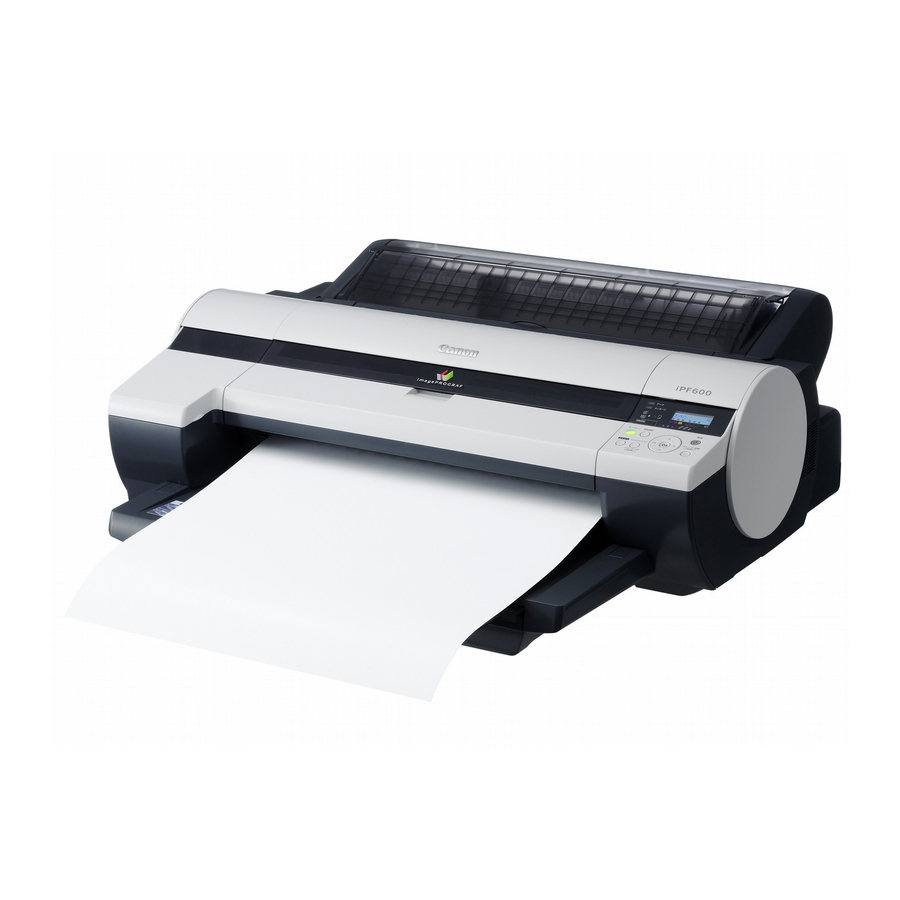
Canon imageprograf ipf600 Service Manual
Hide thumbs
Also See for imageprograf ipf600:
- Service manual (274 pages) ,
- Setup manual (16 pages) ,
- Troubleshooting manual (184 pages)
Subscribe to Our Youtube Channel
Summary of Contents for Canon imageprograf ipf600
- Page 1 SERVICE MANUAL DU7-1182-000 MAY 2006 REV. 0 COPYRIGHT 2006 CANON INC. CANON imagePROGRAF iPF600 REV. 0 PRINTED IN U.S.A. fineline6...
- Page 2 Contents Contents Chapter 1 PRODUCT DESCRIPTION 1.1 Product Overview....................1-1 1.1.1 Product Overview....................... 1-1 1.2 Features......................1-2 1.2.1 Printhead ........................1-2 1.2.2 Ink Tank ........................1-2 1.2.3 Cutter ........................... 1-2 1.2.4 Auto Roll Feed Unit....................1-2 1.2.5 Consumables......................1-3 1.3 Product Specifications..................1-4 1.3.1 Product Specifications....................
- Page 3 Contents 1.7.3.4 Precautions for Disassembly/Reassembly..............1-33 1.7.3.5 Self-diagno stic Feature ....................1-33 1.7.3.6 Disposing of the Lithium Battery ..................1-33 Chapter 2 TECHNICAL REFERENCE 2.1 Basic Operation Outline ..................2-1 2.1.1 Printer Diagram ......................2-1 2.1.2 Print Driving........................ 2-2 2.2 Firmware ......................2-2 2.2.1 Operation Sequence at Power-on ................
- Page 4 Contents 2.4.5 Maintenance Cartridge Relay PCB ...............2-50 2.4.5.1 Maintenance cartridge relay PCB components ............. 2-50 2.4.6 Power Supply ......................2-50 2.4.6.1 Power supply block diagram..................... 2-50 2.5 Detection Functions with Sensors ..............2-51 2.5.1 Sencors for covers ....................2-51 2.5.2 Ink passage system ....................2-52 2.5.3 Carriage system .......................
- Page 5 Contents 4.3.9 Roll Feed Unit ......................4-37 4.3.10 Purge Unit....................... 4-41 4.3.11 Waste Ink Collection Unit..................4-43 4.3.12 Ink Tank Unit......................4-47 4.3.13 Head Management Sensor.................. 4-51 4.3.14 Multi Sensor ......................4-52 4.3.15 PCBs ........................4-53 4.3.16 Opening the Cap/Moving the Wiper Unit............4-54 4.3.17 Opening/Closing the Ink Supply Valve ..............
- Page 6 Contents 6.2.4 Power supply ......................6-26 6.2.5 Roll feed unit PCB....................6-27 6.3 Version Up......................6-28 6.3.1 Firmware Update Tool..................... 6-28 6.4 Service Tools ....................6-29 6.4.1 Tool List ........................6-29 Chapter 7 SERVICE MODE 7.1 Service Mode ..................... 7-1 7.1.1 Service Mode Operation ...................
- Page 7 Chapter 4 DISASSEMBLY/REASSEMBLY fineline6...
-
Page 8: Ink Tank
Contents Contents 4.1 Service Parts...................... 4-1 4.1.1 Service Parts....................... 4-1 4.2 Disassembly/Reassembly................4-1 4.2.1 Disassembly/Reassembly..................4-1 4.3 Points to Note on Disassembly and Reassembly ........4-6 4.3.1 Note on assemblies (or units) prohibited from disassembly ....... 4-6 4.3.2 Moving the carriage manually .................. 4-6 4.3.3 Units requiring draining of ink................... -
Page 9: Warnings
Chapter 4 4.1 Service Parts 4.1.1 Service Parts The service parts indicated below require careful handling. 1. Keep all packages with the warning not to turn over. Pay careful attention to all individually packaged service part (carriage unit, purge unit, ink tank unit, and other parts) boxes marked "This side up"... -
Page 10: Troubleshooting
Chapter 6 TROUBLESHOOTING fineline6... -
Page 11: Firmware
Contents Contents 6.1 Troubleshooting....................6-1 6.1.1 Outline ..........................6-1 6.1.1.1 Outline of Troubleshooting....................6-1 6.1.2 Troubleshooting When Warnings Occur ..............6-1 6.1.2.1 Ink Lvl: Chk XX (1000,1001,1002,1003,1006,1007)............6-1 6.1.2.2 MTCart Full Soon (1100)..................... 6-1 6.1.2.3 Mist Full Soon (1101)......................6-2 6.1.2.4 GARO W12xx: xx stands for digits (1221,1222,1223,1225,1231,1232,1233,1234,1235) 6.1.2.5 Feed Limit... -
Page 12: Ink Tank Unit
Chapter 6 6.1 Troubleshooting 6.1.1 Outline 6.1.1.1 Outline of Troubleshooting 1. Outline Troubles subject to troubleshooting are classified into those shown on the display (warning, error, and service call) and those not shown on the display. 2. Precautions for Troubleshooting 1) Check the environmental conditions and the media used for printing. - Page 13 PARTS CATALOG DU7-3164-010 OCTOBER 2007 REV. 1 CANON imagePROGRAF 610 REV. 1 PRINTED IN U.S.A. COPYRIGHT ©2007 CANON INC.
- Page 14 Whenever ordering parts, consult this Parts Catalog for all of the information pertaining to each item. Be sure to include, in the Parts Request, the full item description, the item part number, and the quantity. COPYRIGHT (C) 1999 CANON INC. Use of this manual should be strictly supervised to avoid disclosure of confidential information.
-
Page 15: Carriage Unit
Contents NUMERICAL INDEX iPF610/600(Numerical Index) ............1-1 iPF610/600(Parts Catalog) PRINTER & ACCESSORIES ..........2-1 ROLL UNIT ................2-4 COVERS (1) ................2-8 COVERS (2) ................2-12 ELECTRICAL PART ............2-14 PURGE UNIT ...............2-18 CUTTER UNIT ..............2-20 INK SUPPLY UNIT ..............2-22 LINEAR SCALE & LIFT DRIVE UNIT ........2-24 CARRIAGE UNIT ..............2-26 CARRIAGE &... - Page 16 Canon imagePROGRAF iPF600 _sm06.pdf Canon imagePROGRAF iPF600 _sm06.pdf Canon imagePROGRAF iPF600 _sm06.pdf Canon imagePROGRAF iPF600 _sm06.pdf Canon imagePROGRAF iPF600 _sm06.pdf Canon imagePROGRAF iPF600 _sm06.pdf Canon imagePROGRAF iPF600 _sm06.pdf Canon imagePROGRAF iPF600 _sm06.pdf Canon imagePROGRAF iPF600 _sm06.pdf...


Need help?
Do you have a question about the imageprograf ipf600 and is the answer not in the manual?
Questions and answers