
Subscribe to Our Youtube Channel
Related Manuals for isvi IC-25M Series


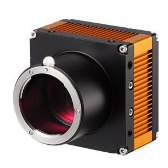
Summary of Contents for isvi IC-25M Series
- Page 1 User’s Manual IC-25M SERIES Digital Monochrome / Color 25Megapixel Camera with Camera Link Interface REV 2.0...
-
Page 2: Table Of Contents
SERIES 1. Precautions ........................4 1.1 General ........................4 1.2 Precautions in Use ....................4 1.3 Maintenance ......................4 2. Overview ........................5 3. Specification ........................5 3.1 Electrical specification ..................... 5 3.2 Electrical shutter specification ................5 3.3 Mechanical spec ..................... 6 3.4 Input signal specification .................. - Page 3 SERIES 6. External Appearance and Dimensions ................21 7. Communication specification ..................22 7.1 Write Command Packet Format ................22 7.1.1 Write Command Packet Format ..............22 7.1.2 Read Command Packet Format ..............22 7.1.3 Read Command Return Packet Format ............22 7.2 Command List ......................
-
Page 4: Precautions
SERIES 1. Precautions 1-1. General ■ Do not drop or damage the device ■ Do not disassemble, repair or alter the device ■ Keep the machine not to be stained with the alien substances ■ Contact your nearest distributor in case of trouble or problem. -
Page 5: Overview
SERIES 2. Overview IC-M25 is a mono area scan CMOS camera and IC-C25 is a color area scan CMOS camera. IC-x25 has 25 million pixels resolution. These Cameras are suitable for a wide range of application within factory Automation, an also for application outside the factory floor, such as AOI(Automatic Optical Inspection), High-end surveillance and medical. -
Page 6: Electrical Shutter Specification
SERIES 3.2 Electrical shutter specification ■ Shutter Speed : -. Shutter OFF or 1/1,000,000 to 10 sec -. The exposure time at shutter OFF is different depending -. on the reading mode.(Factory default : Shutter OFF) ■ Random Trigger Shutter ON / OFF switching (Factory default) -. -
Page 7: Various Safety Standards
SERIES 3.6 Various safety standards ■ Performance assurance -.CE(AoC) Test Standard(2004/108/EC) : EN 55022 : 2006 +A1:2007 [Class A Equipment] EN 55024 : 1998 +A1:2001, +A2:2003 -.FCC(Verification) Test Standard : Section 15.107, Section 15.109 (Class A Equipment) NOTE : This equipment has been tested and found to comply with the limits for a Class A digital device, pursuant to part 15 of the FCC Rules. -
Page 8: Sensor Information
SERIES 3.7 Sensor Information 3.7.1 Spectral response Mono Fig 3.1 Spectral response 3.7.2 Spectral response Color Fig 3.2 Spectral response... -
Page 9: Camera Interface
-. Flashing at 0.25 second intervals : camera operates in Trigger Slaver Mode. -. Flashing at 0.125 second intervals : camera operates in Free Run Mode. Fig 4.1 IC-25M SERIES CONNECTOR 4.2 Camera Link Connector (1) Video output/controlling (Camera Link Full Configuration) CAMERA LINK0, LINK1... - Page 10 SERIES ▷ Connector type: MDR 26-PIN connector 10226-52A2PL (Manufactured by 3M) Fig 4.2 Camera Link0 Connector Pin No Signal Name Pin No Signal Name Ground Inner shield Ground Inner shield XCLKOUT- XCLKOUT+ INPUT RX+_SERTC+ INPUT RX-_SERTC- TX-_SERTFG- TX+_SERTFG+ INPUT...
-
Page 11: Camera Link Interface
8tap(8bit /10bit) : Camera link1 connector & Camera link2 connector 10tap(8bit) : Camera link1 connector & Camera link2 connector If Camera Link output is set to 2Tap’s (Base) in IC-25M series, transmission and reception of all data are carried out through Camera Link connector 1 and it is not require to connect the cable to Connector 2. -
Page 12: Power Input Connector
SERIES multiplexed signal output interface. The output driver is NS type DS90CR287, and the receiver is NS type DS90CR288. The data bits from the digital video, FVAL, LVAL and DVAL are multiplexed into the twisted pairs, which are a part of the Camera Link. Trigger signals and the serial camera control are feed directly through its own pairs. -
Page 13: Trigger Input Circuit
SERIES Pin No Signal Name INPUT Trigger + INPUT Trigger - GROUND OUTPUT Strobe Output Fig 4.7 Control Connector 4.6 Trigger Input Circuit Following figure shows trigger signal input circuit of 4 pin connector. Trigger signal entered is delivered to internal circuit through photo coupler. Minimum trigger width that can be recognized at camera is 5µs. -
Page 14: Functions And Operations
SERIES Fig 4.5 Strobe Output Schematic 5. Functions and Operations 5.1 Basic Functions The IC-25M cameras is a progressive scan camera with 25 Mega pixels monochrome or Bayer mosaic color CMOS. The interface to the host PC is via digital Camera Link. - Page 15 The pixel array is integrating incident light for the part of the isvi SERIES integration phase during which the shutter is open. As for the previous example, the shutter opens again after the end of the readout phase.
-
Page 16: Trigger Operation
SERIES Fig. 5-2 Controlling the SHUTTER Output 5.2 Trigger operation Trigger mode of camera is divided into Free-Run mode where image is synchronized to Internal Trigger signal created inside camera, and External Sync mode where image is synchronized to the trigger signal entered in external port. -
Page 17: External Sync Mode
SERIES 5.1.3 External Sync Mode In External Sync Mode, camera keeps standby status until trigger signal is entered and performs image transmission (Frame Transfer) after exposure process if trigger input occurs as shown in Fig. 7.4. To operate camera in External Sync mode, it is... - Page 18 SERIES ▷ When new trigger input occurs in Exposure section while Exposure Source is set in Program, the signal is ignored. It is the case that exposure setting value is set longer than trigger input cycle, and since it is not synchronized for all trigger signal entered in camera, Frame Rate gets slower than Trigger input cycle.
-
Page 19: Defective Correction Circuits
SERIES 5.5 Defective Correction Circuits There could be incidence of light-malfunctioning defective pixel in the CMOS. In this case, additional correction is required to enhance the degraded quality of output images. For each camera, defective pixel information of CMOS is encoded during the shipping process. -
Page 20: External Appearance And Dimensions
SERIES 6. External Appearance and Dimensions Fig. 7-1 Fmount Dimension Fig. 7-2 m42 mount Dimension... -
Page 21: Communication Specification
All configuration of the 25M series camera is done via Camera Link. All types of camera setting commands, requiring data transmission are delivered in Hex command type. The camera can be set up from a PC running terminal emulator software, or using iSVi camera control software.(CamIsv) 7.1 Communication Setting: •... -
Page 22: Camera Mode Format
SERIES Medium 4Taps 12Bit : 0X = 05 Full 8Taps 8Bit : 0X = 00 Full 10Taps 8Bit : 0X = 0F 7.2.2 Camera Mode Format [0210004100000XXX03] ▷ Continuous Mode Live Normal Mode : 0XXX = 0601 Live Binging Mode... -
Page 23: Exposure Time Format
SERIES 7.2.4 Exposure Time Format [021000430000XXXX03] & [021000440000XXXX03] & 1usec : XXXX = 001B XXXX = 0001 (Minimum Value) & 1msec : XXXX = 6978 XXXX = 0001 10msec : XXXX = 0207 & XXXX = 0208 & 100msec... -
Page 24: White Balance Format
SERIES Level 251 : XXXX = 45FB Level 252 : XXXX = 45FC Level 253 : XXXX = 45FD Level 254 : XXXX = 45FE Level 255 : XXXX = 45FF (Maximum Value) 7.2.7 White Balance Format [02100006000000XX03] Enable White balance : XX=00... -
Page 25: Test Pattern Format
SERIES 7.2.9 Test Pattern Format [021000D2000000XX03] OFF(Normal) : XX = 00 Pattern 1 : XX = 04 Pattern 2 : XX = 05 Pattern 3 : XX = 06 Pattern 4 : XX = 07... -
Page 26: Camera Control Tool
SERIES 8. Camera Control Tool (GUI) 8.1 camera & frame grabber Connect Camera configuration utility software, the camISV, is provided with change its settings and save the settings a file or in the camera. The configuration utility includes an interactive help file, which will guide you through the camera settings. -
Page 27: Main Windows Control
SERIES 8.2 Main Windows Control Fig. 8-2 Main Windows ■ Output It’s available to check the connection between Grabber and Camera through the Terminal screen displayed command code from PC to Camera. - Page 28 SERIES ■ Information ▶ Model : Camera Model Display ▶ Sensor Rev. : Sensor Version Display ▶ H/W No : Camera PBA Version Display ▶ H/W No : Camera FPGA Firmware Version Display ▶ X size : Camera X Axis Full Resolution (5056) ▶...
- Page 29 SERIES ■ Mode 2 ▶ Off : No Binning & Sub Sampling ▶ Binning(2496*2496): Sensor output to 2x2 Binning. (color camera not acceptable) ▶ Sub Sampling(2496*2496) : Sensor output to 2x2 Sub Sampling mode ■ Test Pattern ▶ Off : Test Pattern Off (Normal Mode) ▶...
- Page 30 SERIES ■ Camera Link Output Format Fig. 8-5 CamIsv Connect ▶ Base : A, B_Two Port Output ▶ Medium : A, B, C, D_Four Port Output ▶ Full _8Tap : A, B, C, D, E, F, G, H_Eight Port Output ▶...
-
Page 31: Trigger / Live Windows Control
SERIES 8.3 Trigger / Live Windows Control Fig. 8-6 Trig/live Windows ■ Continuous Mode ▶ Free Run : Regardless external trigger, it’s output image based on designated exposure time. - Page 32 SERIES ■ Trigger ▶ Trigger/Master : It’s output an image through designated exposure time by Source Trigger (Camera Link & External) ▶ Trigger/Slave : It’s output an image through designated Trig Width by Source Trigger (Camera Link & External) ▶...
-
Page 33: Gain/Awb Windows Control
SERIES 8.4 Gain/AWB Windows Control Fig. 8-8 Gain/AWB Windows ■ Analog Pixel Gain ▶ It’s available to set Camera Gain Value from “0” to “255”. ■ Black Level Offset ▶ It’s available to set Camera Black Level Offset from “0” to 255... - Page 34 SERIES ■ White Balance ▶ Enable White Balance : Enable White Balance function ▶ Bayer Select : Setting for Camera Bayer Pattern (R-G Select) ▶ Red : Set Red Gain Value by Manual [0~2047] ▶ Green : Set Green Gain Value by Manual [0~2047] ▶...
-
Page 35: Correction Windows Control
SERIES 8.5 Correction Windows Control Fig. 8-10 Correction Windows ■ LUT ▶ Look Up Table : Set Gamma value considering the table ▶ Gamma : Set Gamma value (Available to save up to two) ■ Gamma Correction Download 1. gamma value setting 2. -
Page 36: Terminal Windows Control
SERIES ■ Initialize EEPROM ▶ Intializing : Initialize setting value (memory reset) 8.6 Terminal Windows Control Fig. 8-11 Terminal Windows... - Page 37 SERIES ■ Terminal Output ▶ Command code display terminal between PC to camera ▶Clear button : delete displayed command code on the screen. ■ Access Register ▶ Address(Hex) : Input or read address. ▶ ValueHex) : Input or read data value display.
- Page 38 Operation of this equipment in a residential area is likely to cause harmful interference in which case the user will be required to correct the interference at his own expense. Visit our web site at http://www.isvi-corp.com...
Need help?
Do you have a question about the IC-25M Series and is the answer not in the manual?
Questions and answers