
Subscribe to Our Youtube Channel
Summary of Contents for JR ProPo X-378
-
Page 1: Programmable Mixing
INSTRUCTION MANUAL FOR AIRPLANE, HELICOPTER SAILPLANE X-378 7-CHANNEL COMPUTER... -
Page 2: Table Of Contents
Sub Trim 5.12 Wing Type Selection Travel Adjust 5.13 Aux 2/Spoiler Channel Input Select CCPM Swashplate Mixing 6. Function Mode Servo Reversing Throttle Hold Dual-Rates Throttle Curve Exponential 6.10 Pitch Curves Sub Trim 6.11 Inverted Switch X-378 MANUAL Table of Contents... - Page 3 Elevator-to-Flap Mixing Aileron-to-Flap Mixing Differential Aileron Mixing 6.10 Flap to Elevator Mixing 6.11 Flap-to-Aileron Mixing 6.12 Aileron-to-Rudder Mixing 6.13 Crow/Camber Mixing 6.14 Dual-Flap Trim 6.15 Programmable Mixing 1-6 6.16 Fail-Safe/Hold Function (PCM Only) 6.17 Trainer System X-378 MANUAL Table of Contents...
-
Page 4: Introduction
X-378 to suit your personal step will save you a great deal of time. Following preferences. These features are discussed in the... -
Page 5: Receiver
PCM (z or s) or PPM OUTPUT POWER Approximately 750mw Approximately 750mw CURRENT DRAIN 200mA (70mA with DSC) 200mA (70mA with DSC) POWER SOURCE 1.2Vx Ni-Cd (9.6V) 600mAh 1.2Vx Ni-Cd (9.6V) 600mAh OUTPUT PULSE 1000–2000 (1500 Neutral) 1000–2000 (1500 Neutral) X-378 MANUAL Introduction... -
Page 6: Servo Specifications
4682 JR X-378 • ALL 7/23/02 10:07 PM Page 6 SERVO SPECIFICATIONS TYPE TORQUE (ounce inch) 43 oz/in SPEED (sec/60°) .25 60° WEIGHT 1.58 SIZE (in) (W x L x H) 1.52 x 0.73 x 1.32 Single MOTOR 3-Pole Ferrite... -
Page 7: Battery Charging
If you do, any damage that results will not be Be sure to use the proper charger (120mAh) covered by warranty. If you are unsure of compatabily when using battery packs of 1000mAh or larger for issues with your radio, seek expert advice before your receivers. X-378 MANUAL Introduction... -
Page 8: Advanced Digital Trims
(engine off) position. For the next X-378 will allow the Trim lever to be set back to this flight, by simply pressing the Digital Throttle Trim up... -
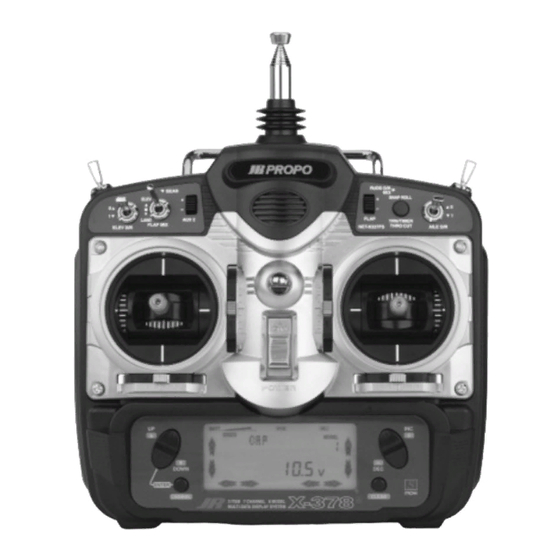
Page 9: Control Identification And Location
ELEV Elevator Channel than half throttle. This gives easy, accurate idle RUDD Rudder Channel adjustments without affecting the high throttle GEAR Gear Channel position. AUX 1 Auxiliary 1 Channel (Flap) AUX 2 Auxiliary 2 Channel (Spoiler) X-378 MANUAL Airplane... -
Page 10: Airplane Version Transmitter
CHANNEL ASSIGNMENT 1. THRO Throttle Channel 5. GEAR Gear Channel 2. AILE Aileron Channel 6. AUX 1 Auxiliarty 1 Channel (Pitch) 3. ELEV Elevator Channel 7. AUX 2 Auxiliary 2 Channel 4. RUDD Rudder Channel (Gyro Sensitivity) X-378 MANUAL Airplane... -
Page 11: Transmitter Rear
(Horizon Service Center). Any transmitter frequency change made by non-certified technician may result in a violation of the FCC rules. THROTTLE TENSION SCREW ELEVATOR TENSION SCREW RUDDER TENSION SCREW AILERON TENSION SCREW X-378 MANUAL Airplane... -
Page 12: Control Stick Length Adjustment
• CONTROL STICK LENGTH ADJUSTMENT To adjust the stick length, use the 2mm Allen wrench (supplied with your X-378 transmitter) to unlock the SET SCREW set screw. Turn the wrench counterclockwise to loosen the screw. Then, turn the stick clockwise to shorten or counterclockwise to lengthen. -
Page 13: Neck Strap Attachment
CHAPTER 1: SOFTWARE FUNCTIONS Airplane • NECK STRAP ATTACHMENT An eyelet is provided on the face of the X-378 Note: Double-check to ensure that the neck transmitter that allows you to connect a Neck Strap strap is securely fastened to the transmitter. -
Page 14: Connections
D.S.C. RECEPTACLE (JRPS024) AUXILIARY 2 CHARGECORD OR D.S.C. AUXILIARY 1 D.S.C.-(JRPA132) GEAR CHARGER-(JRPC221) AUX1 RUDDER GEAR 7 CH 72MHz FM SLIMLINE RUDD RECEIVER ELEV ELEVATOR ABC&W INTERFERENCE PROTECTION SYSTEM A I L E AILERON THRO THROTTLE R700 RECEIVER X-378 MANUAL Airplane... -
Page 15: Alarm And Error Display
All transmitter programs will return to the factory default settings, and the data you have input will be lost. When it becomes necessary to replace the lithium back-up battery, contact JR Horizon X-378 MANUAL Airplane... -
Page 16: Normal Display
DIRECT ACCESS DIGITAL TRIMS The X-378 is equipped with a Direct Access Digital Trim Value function. When at the normal display, if a digital trim lever is moved, the screen will automatically change to show the current trim value for the channel being adjusted. -
Page 17: System Mode
2. Move the power switch to the On (upper) Switch Activation position. pg. 26 3. Use either the Up or Down key to scroll through the Wing menu and access the applicable function. Type pg. 27 Spoiler Channe Input Selection pg. 30 X-378 MANUAL Airplane... -
Page 18: Model Selection/Copy Select
Airplane • MODEL SELECTION/COPY SELECT The X-378 system offers memory for eight completely with each model setup. Another very useful function separate models. Therefore, it is possible to have a of the Model Selection function is the ability to set mixture of helicopter, airplane and glider setups one aircraft up several different ways. - Page 19 6. Now press the Increase or Decrease keys to select the 9. To access the Model Naming function, press the accepting model number. Up key. 10. To exit the Copy Selection function, press the Down and Channel keys simultaneously. X-378 MANUAL Airplane...
-
Page 20: Model Name Entry
CHAPTER 5: SYSTEM MODE Airplane • MODEL NAME ENTRY The X-378 allows a 3-digit name to be input for each of not active. You may also find this useful to identify the eight models available. The current model will be different aircraft setups. -
Page 21: Model Type Selection
CHAPTER 5: SYSTEM MODE Airplane • MODEL TYPE SELECTION The X-378 is capable of performing as a helicopter, airplane or sailplane radio with full functions for each. Model Type Data Reset Press to change Model Naming model type. Accessing the Type Selection Function 1. -
Page 22: Data Reset
LCD display. Be sure that the model selected is the model you want to reset by checking 6. To exit the Data Reset function, press both the the number at the right side of the display. Down and Channel keys simultaneously. X-378 MANUAL Airplane... -
Page 23: Modulation Select
MODULATION SELECT The Modulation Selection function enables your within your receiver or from linear PPM (Pulse X-378 to transmit to a variety of JR receivers that are Position Modulation [FM]). already, or may soon be, in existence. You can select... -
Page 24: Data Transfer
The X-378’s Data Transfer function allows for a model Transmitting Transmitter: It will first be necessary to from one X-378 transmitter to be sent to another X378 select the desired model (1-8) to be transferred to the transmitter by using a JR Trainer Cord (JRPA130 sold receiving transmitter. -
Page 25: Trim Step
Press Clear to reset to the Data Transfer keys to increase or factory default (4) position. decrease the trim step rate. Press Channel to select channel to be adjusted (Throttle, Aileron, Elevator, Aux 2 Lever, Flap Level). X-378 MANUAL Airplane... -
Page 26: Throttle Cut Switch
AUX 2 Switch Selection Press the (+) or (-) Press Clear to reset to the Trim Step factory off position. keys to turn the Throttle Cut function on and off X-378 MANUAL Airplane... -
Page 27: Wing Type Selection
LCD display. Use this wing type with common wing type selection. Your X-378 transmitter will aircraft that utilize only one servo for both of the also return to the normal wing mixing type if the control surfaces. - Page 28 Note: Differential is offered for the Flapperon simultaneously. For a left turn, the opposite is true; function of your X-378. For more information, the left aileron should rise while the right aileron please refer to the Differential section of this drops.
- Page 29 Delta or Elevon is the final Wing Mixing selection in wing itself functions as if it were the elevator. Also, your X-378. This style of aircraft also employs two wing when an aileron control is given, the two wing servos servos.
-
Page 30: Aux 2/Spoiler Channel Input Select
LCD. 3. Press either the (+) or (-) key to assign the desired switch (LEVRG or MIX SW) 4. To access the Wing Type function, press the Down key. X-378 MANUAL Airplane... -
Page 31: Function Mode
3. Use either the Up or Down to scroll through the Programmable menu and access the applicable function. Mixing pg 50 Fail-Safe (only visible when PCM Modulation is selected) pg. 52 Trainer Function pg. 59 Timer Function pg. 62 X-378 MANUAL Airplane... -
Page 32: Servo Reversing
The Reverse Switch function is an electronic means of direction. This will ease setup during the servo reversing the throw of a given channel (servo). All installation into your aircraft. seven channels of the X-378 offer reversible servo THRO: Throttle AILE:... -
Page 33: Dual-Rates
0-125% for each switch position to adjust the rate. The number to the upper right of and channel. the current rate value on the display indicates the current position of the Dual-Rate switch for the X-378 MANUAL Airplane... - Page 34 Auto D/R function for Flight mode 1. Press the screen will change from 0 to 1 as the switch the (+) or (-) keys to turn the function on or off. Repeat is moved. this procedure for flight modes 2 and X-378 MANUAL Airplane...
-
Page 35: Exponential
9. To access the Sub-Trim function, press the Up key. select the opposite switch position, move the 10. To exit the Exponential Function, press the Down appropriate Dual-Rate or Flight mode switch to the and Channel keys simultaneously. opposite position. The number that appears directly X-378 MANUAL Airplane... - Page 36 Press the Clear key to Press the (+) or (-) reset to the factory keys to turn the AUTO Dual-Rate default position (Off). function on and off. Press Channel to access AUTO rate function from exponential screen. X-378 MANUAL Airplane...
- Page 37 0 to 1 as the high (full) position. the throttle stick is moved. X-378 MANUAL Airplane...
-
Page 38: Sub Trim
Note: A (+) or (-) symbol appears to the left of 7. To access the Travel Adjust function, press the Up key. the sub trim value to indicate the direction of 8. To exit the Sub-Trim function, press the Down and Sub-Trim input. Channel keys simultaneously. X-378 MANUAL Airplane... -
Page 39: Travel Adjust
The factory default (Data Reset) servo operation. The X-378 offers travel adjust for all value is 100% for each direction of servo travel. seven channels. The Travel Adjust range... -
Page 40: Elevator-Toflap Mixing
9.To exit the Elevator-to-Flap Mixing function, press arrow or vice-versa. A down arrow indicates up the Down and Channel keys simultaneously. elevator, and an up arrow indicates down X-378 MANUAL Airplane... - Page 41 Using our example, we would input value will still be displayed, it will not be down elevator. The down arrow would be possible to alter this value until the mix displayed at the lower left switch is returned to the on position. X-378 MANUAL Airplane...
-
Page 42: Aileron-To-Rudder Mixing
"OFF." The current mixing switch must be in Up key. the On position in order to make adjustments 7. To exit the Aileron-to-Rudder Mixing function, to the Aileron- to-Rudder mixing value. press the Down and Channel keys simultaneously. X-378 MANUAL Airplane... - Page 43 RUDD" appears in the center portion of your LCD. press the Down and Channel keys simultaneously. 4. Press the Channel key to access the switch assignment function. 5. Press the (+) or (-) key to select the desired switch/function to activate the Aileron-to-Rudder Mixing function. X-378 MANUAL Airplane...
-
Page 44: Mode Function
To check to see that the Aux2 lever 5. To exit the Landing Mode function, press the Down has been de-activated, move the Aux2 lever while at and Channel keys simultaneously. the Aux2 switch selection screen. If the lever is X-378 MANUAL Airplane... - Page 45 Snap Roll Function Press the (+) or (-) key to reset to the factory set the Landing Mode default position. position for each channel. Aileron-to-Rudder Mixing Press the Channel Key to select the desired channel to be adjusted. X-378 MANUAL Airplane...
-
Page 46: Snap Roll Function
The rudder only; all other functions work as normal. While X-378 offers four separate directions of snap rolls the snap roll switch is activated, the related sticks will not operate until the switch is released. When this... - Page 47 Snap Roll Function is inhibited. Snap roll direction—the example shown is Right-Down (R-DN) Press to select Up Press to select Right Snap Roll. Press to select Snap Roll. Press to select Down Left Snap Roll. Snap Roll. X-378 MANUAL Airplane...
-
Page 48: Differential Aileron Mixing
Airplane • DIFFERENTIAL AILERON MIXING 6.11 The X-378 transmitter offers aileron differential for the to correct for this common flight tendency. Aileron flapperon and delta-wing mixing selections. differential overcomes the yaw as it reduces the Differential ailerons are used to tailor the flight control downward travel of the ailerons. - Page 49 4. To access the Snap Roll function, press the Down key. SPLT: 100% Differential 5. To access the Flap Lever Adjustment, press the Up key. 6.To exit the Aileron Differential Mixing function, press the Down and Channel keys simultaneously. X-378 MANUAL Airplane...
-
Page 50: Landing Attitude
LCD. press the Up key. 4. Press the Clear key to select the desired function to 8. To exit the Flap Lever Adjustment function, press be adjusted (TRIM, OFF, FULL). the Down and Channel keys simultaneously. X-378 MANUAL Airplane... -
Page 51: Programmable Mixing
Airplane • 6.13 PROGRAMMABLE MIXING 1-6 The X-378 offers six programmable mixes to be used Each channel of this radio is identified by an for any number of different purposes. This function abbreviated name. The chart below indicates the allows mixing any one channel to any other channel to channel and its corresponding abbreviation. - Page 52 Setting the Mixing Switch Activation ELE>F: Activated in the ELEV position of the Flap Mix 9. Press the Channel key once again. The display will switch have "SW ON" indicated at the center portion of the X-378 MANUAL Airplane...
- Page 53 Setting the Mixing Channel Offset Setting the Mixing Values 1. Press the Channel key once again. The display will The X-378 transmitter has six multi-purpose show the current mixing channels at the top of the 4 programmable mixes available. For these mixing LCD, with the word "OFFSET"...
- Page 54 Include Mixing reduces the number of mixing remain stationary. Also, if the mixing programs needed when using multiple mixing percentages are minute, the movement of the functions. slave channel from the trim lever is also minute. X-378 MANUAL Airplane...
-
Page 55: Fail Safe/Hold
FAIL SAFE/HOLD FUNCTION (PCM ONLY) The Fail-Safe/Hold function is available only when the use of a PPM receiver and the transmitter you use the X-378 transmitter in either of the PCM in the PPM modulation. Since the actual modulations-S-PCM or Z-PCM. This function is... - Page 56 Clear key is pressed indicating that the positions Channel keys simultaneously. have been memorized. 5. To confirm that the input of data was successful, switch the transmitter off. The controls will move to the input locations. If not, repeat Step 4 again. X-378 MANUAL Airplane...
- Page 57 Selection section for more information. On position. Fail-Safe/Hold Combination in S-PCM Modualtion The X-378 allows you to combine the Hold and Fail- The predetermined servo positions are set by you. In Safe presets for all seven channels on the receiver.
- Page 58 Press the Clear key to store select the desired Programmable Keys to select Hold the fail-safe servo positions channel to be Mix 6 for all channels set to F.S. (HO) or Fail-Safe programmed. (F.S.) modes for each channel. X-378 MANUAL Airplane...
-
Page 59: Trainer System
• Trainer System 6.15 2) Programmable Function Trainer The X-378 transmitter employs two separate types of Individual Channel functions may be assigned to the trainer systems: slave one at a time. Since the control functions can be transferred one by one, students can concentrate on... - Page 60 6. To change the Programmable Trainer Function back 9. To exit the Trainer function, press the Down and to the Normal Trainer System, press the Clear key. Channel keys simultaneously. 7. To access the Fail-Safe function, press the Down key. X-378 MANUAL Airplane...
- Page 61 PPM/PCM selectable, select PPM. The master transmitter can be PCM or PPM. Note: If the master transmitter is the X-378, 2.Plug the trainer cord (optional part #JRPA130) into the LCD will indicate "TRINR" (Trainer Master) each transmitter's DSC/Trainer jack.
-
Page 62: Timer Function
When the X-378 is being used as the When used as the Stopwatch, the timer will count up master transmitter in the Training function the to 44 minutes 59 seconds, at which time it will reset to zero and continue to count. - Page 63 Press the Channel key To access Reversing function, the assigned timer value. to start/stop the timer. the Trainer press the Up key. function, press the To exit the Timer function, press the Down and Down key. Channel keys simultaneously. X-378 MANUAL Airplane...
-
Page 64: Practical Applications
• To achieve the final mixing percentage, fly your aircraft and make adjustments as necessary. For Travel Adjustment values, use the Travel-Adjust function. 3. Dual-Elevator Servo Operations This is most applicable in quarter scale aircraft where one servo is not enough for the elevator controls. X-378 MANUAL Airplane... -
Page 65: Data Sheet
CHAPTER 8: PRACTICAL APPLICATIONS Airplane • X-378 MANUAL Airplane... -
Page 66: Transmitter Controls
Channel Key Clear Key LCD Display RECEIVER CHANNEL ASSIGNMENT THRO Throttle Channel AILE Aileron Channel ELEV Elevator Channel RUDD Rudder Channel GEAR Gear Channel AUX 1 Auxiliary 1 Channel (Pitch) AUX 2 Auxiliary 2 Channel (Gyro Sensitivity) X-378 MANUAL Helicopter... - Page 67 Gear Channel AILE Aileron Channel (Left Aileron Channel–AIL 2) ELEV Elevator Channel AUX 1 Auxiliary 1 Channel RUDD Rudder Channel (Left Flap Channel for Dual Flaps) AUX 2 Auxiliary 2 Channel (Right Flap Channel for Dual Flaps) X-378 MANUAL Helicopter...
-
Page 68: Transmitter Rear
FCC rules. TRANSMITTER CRYSTAL DSC/ TRAINER JACK CHARGING JACK FOR NI-CD BATTERY ONLY (8N-550) THROTTLE TENSION SCREW ELEVATOR TENSION SCREW RUDDER TENSION SCREW AILERON TENSION SCREW X-378 MANUAL Helicopter... -
Page 69: Control Stick Length Adjustment
• CONTROL STICK LENGTH ADJUSTMENT To adjust the stick length, use the 2mm Allen wrench (supplied with your X-378 transmitter) to unlock the SET SCREW set screw. Turn the wrench counterclockwise to loosen the screw. Then, turn the stick clockwise to shorten or counterclockwise to lengthen. -
Page 70: Neck Strap Attachment
(JRPA156) to attach the antenna to your An optional base-loaded antenna is available for use X-378. The Base Loaded Antenna (JRPA155) is made with the X-378 transmitter. It is considerably shorter of a flexible coil and is covered with a soft plastic than the standard antenna. -
Page 71: Connections
D.S.C. RECEPTACLE (JRPS024) AUX 2 CHARGECORD OR D.S.C. AUXILIARY 1/PITCH D.S.C.-(JRPA132) GEAR CHARGER-(JRPC221) AUX1 GEAR RUDDER 7 CH 72MHz FM SLIMLINE RUDD RECEIVER ELEV ABC&W INTERFERENCE ELEVATOR PROTECTION SYSTEM A I L E THRO AILERON THROTTLE R700 RECEIVER X-378 MANUAL Helicopter... -
Page 72: Key Input And Display
All transmitter programs will return to the factory default settings, and the data you have input will be lost. When it becomes necessary to replace the lithium back-up battery, contact JR Horizon Service Center. Due to the possibility of extensive X-378 MANUAL Helicopter... -
Page 73: System Mode
Clear key to reset the timer. DIRECT ACCESS DIGITAL TRIMS The X-378 is equipped with a Direct Access Digital Trim Value function. When at the normal display, if a digital trim lever is moved, the screen will automatically change to show the current trim value for the channel being adjusted. -
Page 74: Function Mode
Accessing the System Mode 1. Press the Up and Down keys simultaneously. 2. Move the power switch to the On (upper) position. 3. Use either the Up or Down to scroll through the menu and access the applicable function. X-378 MANUAL Helicopter... -
Page 75: Model Selection/Model Copy Select
Helicopter • MODEL SELECTION/MODEL COPY SELECT The X-378 system offers memory for eight completely with each model setup. Another very useful function separate models. Therefore, it is possible to have a of the Model Selection function is the ability to set mixture of helicopter, airplane and glider setups one aircraft up several different ways. - Page 76 6. Press the Increase or Decrease keys to select the 10. To exit the Copy Selection function, press the accepting model number. Down and Channel keys simultaneously. Note: Always make sure that the accepting model is either free of input or one which you X-378 MANUAL Helicopter...
-
Page 77: Model Name Entry
CHAPTER 5: SYSTEM MODE Helicopter • MODEL NAME ENTRY The X-378 allows a 3-digit name to be input for each of not active. You may also find this useful to identify the eight models available. The current model will be different aircraft setups. -
Page 78: Model Type Selection
CHAPTER 5: SYSTEM MODE Helicopter • MODEL TYPE SELECTION The X-378 is capable of performing as a helicopter, airplane or glider radio with full functions for each. Model Type Data Reset Change model Model Naming type Accessing the Type Selection Function 1. -
Page 79: Data Rest
LCD display. Check the number at the right side of the display to be sure the model 6. To exit the Data Reset function, press both the selected is the model you want to reset. Down and Channel keys simultaneously. X-378 MANUAL Helicopter... -
Page 80: Modulation Select
MODULATION SELECT The Modulation Selection function enables your within your receiver or from linear PPM (Pulse X-378 to transmit to a variety of JR receivers that are Position Modulation [FM]). already, or may soon be, in existence. You can select... -
Page 81: Data Transfer
Helicopter • DATA TRANSFER FUNCTION The X-378’s Data Transfer function allows for a model Transmitting Transmitter: It will first be necessary to from one X-378 transmitter to be sent to another select the desired model (1-8) to b transferred to the receiving transmitter. - Page 82 Up or Down keys until the words “TXOUT” appears on by mode. The word “RX IN” will now be indicated on the screen. This is the Data Transfer program. the screen. 4. Receiving Mode Transmitter (TX to receive programming): Press the Channel key until the screen X-378 MANUAL Helicopter...
- Page 83 At this time, press the Clear key Note: The Data Transfer function will not to stop the receiving function. If there is any failure of work when the battery alarm is flashing. transferring, the display will appear as follows: X-378 MANUAL Helicopter...
-
Page 84: Trim Step
Press Clear to reset to the factory default 4 position. to increase or decrease Data Transfer the trim step rate. Press Channel to select channel to be adjusted (Throttle, Aileron, Elevator, Hover Pitch Lever, Hover Throttle Lever). X-378 MANUAL Helicopter... -
Page 85: Throttle Cut Switch Activation
AUX 2 Switch Selection Press Clear to reset to the Trim Step Press the (+) or (-) factory off position. keys to turn the Throttle Cut function on and off. X-378 MANUAL Helicopter... -
Page 86: Aux/Gear Function Select
4. Pressing the Clear key will reset the AUX 2 7. To exit the AUX 2/Gear channel input selection activation switch to the AUX 2 switch. function, press the Down and Channel keys 5. Pressing the Channel key will select the Gear simultaneously. channel switch activation. X-378 MANUAL Helicopter... -
Page 87: Swashplate Type
Helicopter • SWASHPLATE TYPE 5.13 The Swashplate Mixing function enables the X-378 Note: Although the X-378 Swashplate Mixing system to operate many different types of swashplate Type screen displays 4SERV 90 CCPM mixing, control systems, including 3 versions of CCPM. -
Page 88: Function Mode
3. Use either the Up or Down to scroll through the Function pg.106 menu and access the applicable function. Programmable Mixing 1-3 pg.110 Fail-Safe (only visible when PCM Modulation is selected) pg.114 Trainer Function pg.117 Timer Function pg.119 X-378 MANUAL Helicopter... -
Page 89: Servo Reversing
The Reverse Switch function is an electronic means of direction. This will ease setup during the servo reversing the throw of a given channel (servo). All installation into your aircraft. seven channels of the X-378 offer reversible servo Channel to be adjusted Dual-Rate Press the (+) or (-) -
Page 90: Dual-Rates
0-125% for each switch position adjust the rate. The number to the upper right of the and channel. current rate value on the display indicates the current position of the dual rate switch for the X-378 MANUAL Helicopter... - Page 91 “D/RAT“, and the D/R switch position at the far right the (+) or (-) keys to turn the function on or off. Repeat of the screen will change from 0 to 1 as the switch is this procedure for flight modes 2 and moved. X-378 MANUAL Helicopter...
-
Page 92: Exponential
9. To access the Sub-Trim function, press the Up key. select the opposite switch position, move the 10. To exit the Exponential Function, press appropriate Dual-Rate or Flight mode switch to the the Down and Channel keys simultaneously. opposite position. The number that appears directly X-378 MANUAL Helicopter... -
Page 93: Sub Trim
7. To access the Travel Adjust function, press the Up key. Note: A (+) or (-) symbol appears to the left of 8. To exit the Sub-Trim function, press the Down and the sub trim value to indicate the direction of Channel keys simultaneously. Sub-Trim input. X-378 MANUAL Helicopter... -
Page 94: Travel Adjust
The factory default (data reset) servo operation. The X-378 offers travel adjust for all value is 100% for each direction of servo travel. seven channels. The travel adjust range... -
Page 95: Ccpm Swashplate Mixing
The CCPM Swashplate Mixing Function(Cyclic only displayed when Swashplate types 2Serv, Collective Pitch Mixing) of the X-378 is designed to allow the X-378 to be used in model helicopters that 3Serv or 4Serv CCPM are selected in the utilize 2-servo(180°), 3-servo(120°) and 3-servo(90°) Swashplate type Selection in System Mode. - Page 96 3 Servo/90° CCPM (JR style, most popular) 1). 1 servo (Standard Mechanical Mixing) Note: Although the display of the X-378 The most common form of Swashplate Mixing. This indicates 4 Servo 90° CCPM, this is actually 3 type uses each of the three servo to move the Servo 90°...
-
Page 97: Throttle Hold
The adjustable range is (-20%-+50%). Once you establish Up key. the proper idle value for your engine, you can use this 8. To exit the Throttle Hold function, press the Down value for throttle hold as well. To shut the and Channel keys simultaneously. X-378 MANUAL Helicopter... -
Page 98: Throttle Curve
CHAPTER 6: FUNCTIONS (FUNCTION MODE) Helicopter • THROTTLE CURVES The X-378 offers three (3) separate throttle curves with Note: The throttle trim and hovering throttle five adjustable points per curve. This function allows levers are only operable when the flight mode you to customize the throttle curve and pitch curve switch is in the normal position. -
Page 99: Accessing The Throttle Curve Function
Normal mode. adjustments to the engine idle speed position. The throttle trim lever has no effect on positions 1, 2, or in throttle hold. X-378 MANUAL Helicopter... - Page 100 1 and 2. Point L Throttle Stick Throttle Curve Exponential With the X-378 system, individual throttle curves are selectable to be either straight (linear) or curved (exponential) setting.With the exponential function on, you will notice that any sharp angles of the throttle curve will become more “rounded”...
-
Page 101: Pitch Curves
Down key four times. 0-100% in .5% intervals. 10. To exit the Pitch Curve function, press the Down and Channel keys simultaneously. Note: In each curve, the factory setting - - indicates Inhibited for points 1 and 3. These X-378 MANUAL Helicopter... - Page 102 0 to 100 to ease your understanding of other curves. Throttle Pitch 100% 100% Normal Hover Pitch Throttle 100% 100% Stunt 1 Acrobatics Throttle Pitch 100% 100% Stunt 2 Pitch 100% Throttle Hold X-378 MANUAL Helicopter...
-
Page 103: Inverted Switch
When the Inverted Flight Caution: If you do not intend to use the Function is active, the word “OFFSET” will appear Inverted Flight function, leave this function’s below “INVRT.” If the invert switch is operation inhibited. X-378 MANUAL Helicopter... -
Page 104: Revolution Mixing
The X-378 offers two separate revolution mixing from D through Hover (mid) and to the U setting. programs, with independent up and down mixing for... - Page 105 7. To access the Gyro Gain function, press the Up key. 4. Press the Channel key until “ACC.” appears at the 8. To exit the Revolution Mixing function, press the center of the LCD. Down and Channel keys simultaneously. X-378 MANUAL Helicopter...
-
Page 106: Gyro Gain Function
Helicopter • GYRO GAIN FUNCTION 6.13 The X-378 offers two different types of Gyro Sensitivity automatically through the flight mode switch. If you Adjustments: manual or automatic. This feature gives do not intend to use this function, leave this the user the choice of selecting gyro sensitivity through operation at the factory default position (off). - Page 107 Gyro Sensitivity Range 0 to 100% 3. To exit the Gyro Gain function, press the Down and 1. To access the Revolution Mixing function, press Channel keys simultaneously. the Down key. 2. To access the Programmable Mixing function, press the Up key. X-378 MANUAL Helicopter...
- Page 108 Repeat Steps 5 through 7 above to select the gain press the (+) or (-) keys and the screen will change to positions (0 or 1) for each of the remaining flight read “GYR-1.” Press the Channel key twice modes. X-378 MANUAL Helicopter...
-
Page 109: Flight Modes
Recommended Gyro Gain positions Normal (G.NOR) Stunt (G.STN) Hold (G.HLD) Inverted(G.INV) Gyro Remote Gain Connections: JR G460T and Other Connect the white connector to from the G460T to Remote Gain Gyros the AUX2 channel of the receiver. X-378 MANUAL Helicopter... -
Page 110: Programmable Mixing
• PROGRAMMABLE MIXING 1-3 6.14 The X-378 offers three programmable mixes to be used the throttle will increase or decrease based on the for any number of different purposes. This function value of the input. Mixing is proportional, so small... - Page 111 The chart the Off position, the mixing value will indicate below lists the indication seen on the LCD display and “Off.“ its definition. Pressing the (+) or (-) key will change the mixing On/Off switches. X-378 MANUAL Helicopter...
- Page 112 10. Press the Down key to access the Gyro Gain only limited by your imagination. function. 11. Press the Up key to access the Programmable Mix #2 and #3. 12. Press the Down and Channel keys simultaneously to exit the Programmable Mixing function. X-378 MANUAL Helicopter...
- Page 113 Please note that when using any programmable mix rotor absorbs power and the main rotor rpm decays. coupled to the throttle channel of the X-378, it will be This can be compensated for by mixing rudder-to- necessary to increase the high throttle travel position...
-
Page 114: Pcm Fail-Safe/Hold Function
Refer to the Modulation Mode servos assume their preset positions. Selection section for more information. You should never attempt to adjust the Fail- Safe function when the aircraft is running. X-378 MANUAL Helicopter... - Page 115 Press the (+) or (-) keys the Fail-Safe servo positions to select the Hold (HO) or for all channels set to F.S. Programmable Mix 3 Fail-Safe (F.S.) modes for each channel. Press Channel to select the desired channel to be programmed. X-378 MANUAL Helicopter...
- Page 116 Continuing our example, hold the aileron stick to the transmitter automatically recalls the settings right and press the Clear key. 6. Press the Down key. Your Fail-Safe preset value will for the latest Fail-Safe adjustment. be displayed on the LCD. X-378 MANUAL Helicopter...
-
Page 117: Trainer System
Helicopter • TRAINER SYSTEM 6.16 The X-378 transmitter employs two separate types of 2. Programmable Function Trainer Stick functions may be trainer systems: assigned to the slave one at a time. Since the control 1. Normal Trainer System - All functions are... - Page 118 Use of the Programmable Trainer Function (PTF) In this mode, the master may assign functions to the Note: When all channels are set to master, student one at a time to make learning to fly easier. the Trainer System becomes Normal. X-378 MANUAL Helicopter...
-
Page 119: Timer Function
44 minutes 59 the snap roll/trainer switch at the left- rear portion of seconds, at which time it will reset to zero and the transmitter. When the X-378 is being used as the continue to count. master transmitter in the Training... - Page 120 5. To access the Timer function, press the Down key. 6. To access the Dual-Rate function, press the Up key. 7. To exit the Integral Timer unction, press the Up and Down keys simultaneously. X-378 MANUAL Helicopter...
-
Page 121: Data Sheet
4682 JR X-378 • ALL 7/23/02 10:08 PM Page 121 CHAPTER 7: DATA SHEET Helicopter • X-378 MANUAL Helicopter... -
Page 122: Control Identification And Location
Throttle ALT This function makes the throttle stick trim active only which allows for fine adjustment of the spoilers with when the throttle stick is at less than half throttle, the throttle stick in the lower position. X-378 MANUAL Sailplane... -
Page 123: Airplane Mode
Scroll Buttons Clear Key Channel Key LCD Display CHANNEL ASSIGNMENT THRO Throttle Channel GEAR Gear Channel AILE Aileron Channel AUX 1 Auxiliary 1 Channel (Pitch) ELEV Elevator Channel AUX 2 Auxiliary 2 Channel RUDD Rudder Channel (Gyro Sensitivity) X-378 MANUAL Sailplane... -
Page 124: Transmitter Rear
(Horizon Service Center). Any transmitter frequency change made by non-certified technician may result in a violation of the FCC rules. SPOILERS TENSION SCREW ELEVATOR TENSION SCREW RUDDER TENSION SCREW AILERON TENSION SCREW X-378 MANUAL Sailplane... -
Page 125: Control Stick Length Adjustment
CONTROL STICK LENGTH ADJUSTMENT To adjust the stick length, use the 2mm Allen wrench (JRPA047) that is approximately one inch longer than (supplied with your X-378 transmitter) to unlock the the standard stick. This stick, crafted from bar stock set screw. -
Page 126: Neck Strap Adjustment
CHAPTER 1: CONNECTIONS Sailplane • NECK STRAP ATTACHMENT An eyelet is provided on the face of the X-378 Note: Double-check to ensure that the neck transmitter that allows you to connect a Neck Strap strap is securely fastened to the transmitter. -
Page 127: Connections
(JRPS024) AUXILIARY 2 CHARGE CORD OR D.S.C. AUXILIARY 1 D.S.C.-(JRPA132) GEAR CHARGER-(JRPC221) AUX1 GEAR RUDDER 7 CH 72MHz FM SLIMLINE RUDD RECEIVER ELEV ABC&W INTERFERENCE ELEVATOR A I L E PROTECTION SYSTEM THRO AILERON THROTTLE/SPOILER R700 RECEIVER X-378 MANUAL Sailplane... -
Page 128: Key Input And Display
All transmitter programs will return to the factory default settings, and the data you have input will be lost. When it becomes necessary to replace the lithium back-up battery, contact JR Horizon Service Center. Due to the possibility of extensive X-378 MANUAL Sailplane... -
Page 129: Model Setup Mode
Channel key to Start/Stop the timer. the timer. DIRECT ACCESS DIGITAL TRIMS The X-378 is equipped with a Direct Access Digital Trim Value function. When at the normal display, if a digital trim lever is moved, the screen will automatically change to show the current trim value for the channel being adjusted. -
Page 130: Function Mode
1. Press the Down and Channel keys simultaneously. Wing Type 2. Move the power switch to the On (upper) position. pg. 141 3. Use either the Up or Down to scroll through the menu and access the applicable function. Flap/Spoiler Lever Selection pg. 143 X-378 MANUAL Sailplane... -
Page 131: Model Selection/Model Copy Select
Sailplane • MODEL SELECTION/MODEL COPY SELECT The X-378 system offers memory for eight completely with each model setup. Another very useful function separate models. Therefore, it is possible to have a of the Model Selection function is the ability to set mixture of helicopter, airplane and sailplane setups one aircraft up several different ways. - Page 132 6. Press the Increase or Decrease keys to select the 10. To exit the Copy Selection function, press the accepting model number. Down and Channel keys simultaneously. Note: Always make sure that the accepting model is either free of input or one that you X-378 MANUAL Sailplane...
-
Page 133: Model Name Entry
CHAPTER 5: INPUT MODE AND FUNCTION Sailplane • MODEL NAME ENTRY The X-378 allows a 3-digit name to be input for each of not active. You may also find this useful to identify the eight models available. The current model will be different aircraft setups. -
Page 134: Model Type Selection
CHAPTER 5: INPUT MODE AND FUNCTION Sailplane • MODEL TYPE SELECTION The X-378 is capable of performing as a helicopter, airplane or sailplane radio with full functions for each. Current Model Type Model Type Data Reset Change Model Type Model Naming Accessing the Type Selection Function 1. -
Page 135: Data Rest
LCD display. Check the number at the right side of the display to be sure the model 6. To exit the Data Reset function, press both the selected is the model you want to reset. Down and Channel keys simultaneously. X-378 MANUAL Sailplane... -
Page 136: Modulation Select
The Modulation Selection function enables your depending on the Central Processing Unit (CPU) within X-378 to transmit to a variety of JR receivers that are your receiver or from linear PPM (Pulse Position already, or may soon be, in existence. You can select Modulation [FM]). -
Page 137: Data Transfer Function
Sailplane • DATA TRANSFER FUNCTION The X-378’s Data Transfer function allows for a model Transmitting Transmitter: It will first be necessary to from one X-378 transmitter to be sent to another select the desired model (1-8) to be transferred to the receiving transmitter. - Page 138 LCD directly over the automatically) current model number selected. 2. Press the Channel key to select transmit (TX) or 5. Select the receiving model number by pressing the receive (RX) modes. (+) and (-) keys. X-378 MANUAL Sailplane...
- Page 139 100% completed) Trim Step Press to select Transmit (TX) Press the Clear key to activate or Receive (RX) modes the receiving Standby mode. Modulation Select The letters “RX IN” will now be indicated on the screen. X-378 MANUAL Sailplane...
-
Page 140: Trim Step
Press the (+) or (-) keys factory default 4 position. Data Transfer to increase or decrease the trim step rate. Press Channel to select channel to be adjusted (Throttle, Aileron, Elevator, Flap Trim, Lever, Flap Trim Lever). X-378 MANUAL Sailplane... -
Page 141: V-Tail/Dual Flap Wing Mixing
V-TAIL/DUAL-FLAP WING MIXING 5.11 V-tail and/or dual-flap wing type. The V-Tail/Dual-Flap Wing Mixing function found in the X-378 allows the user to set the aircraft type as a Function to be adjusted Condition of function (Off or On) Press the Clear key to... - Page 142 3. To activate the V-Tail Mix function, press either the and Channel keys simultaneously. (+) or (-) keys. 4. To access the Dual-Flap function, press the Channel key. Next, press the (+) or (-) keys to activate the Dual- Flap Mix. X-378 MANUAL Sailplane...
-
Page 143: Flap Switch Select Function
6. To exit the Flap/Spoiler Select function, press the “LEVRS” in the center of the LCD. Down and Channel keys simultaneously. 3. Press either the (+) or (-) key to assign the desired switch method (LEVRS or FL+LS) X-378 MANUAL Sailplane... - Page 144 3. Use either the Up or Down to scroll through the menu and access the applicable function. Programmable Mixing 1-6 pg. 167 Fail-Safe (only visible when PCM Modulation is selected) pg. 171 Trainer Function pg. 175 Timer Function pg. 177 X-378 MANUAL Sailplane...
-
Page 145: Servo Reversing
The Reverse Switch function is an electronic means of direction. This will ease setup during the servo reversing the throw of a given channel (servo). All installation into your aircraft. seven channels of the X-378 offer reversible servo Channel to be adjusted Dual-Rate Function... -
Page 146: Dual Rates
5. Select the switch position for which you want to 125% for each switch position and channel. adjust the rate. The number to the upper right of the current rate value on the display indicates the current position of the dual rate switch for the X-378 MANUAL Sailplane... - Page 147 9. To exit the Dual-Rate function, press the Down and the Clear key. After the dual rates have been Channel keys simultaneously. dialed in to your satisfaction, we suggest that you begin to adjust the exponential values. Refer to the Exponential section for more information. X-378 MANUAL Sailplane...
-
Page 148: Exponential
9. To access the Sub-Trim function, press the Up key. appropriate Dual-Rate or Flight mode switch to the 10. To exit the Exponential Function, press opposite position. The number that appears directly the Down and Channel keys simultaneously. X-378 MANUAL Sailplane... -
Page 149: Sub Trim
7. To access the Travel Adjust function, press the Up key. Note: A (+) or (-) symbol appears to the left of 8. To exit the Sub-Trim function, press the Down and the sub-trim value to indicate the direction of Channel keys simultaneously. sub-trim input. X-378 MANUAL Sailplane... -
Page 150: Travel Adjust
The factory default (data reset) servo operation. The X-378 offers travel adjust for all value is 100% for each direction of servo travel. seven channels. The travel adjust range... -
Page 151: Elevator-To-Flap Mixing
Using our example, Activation section for more information. we would input down elevator. The down arrow would be displayed at the lower left portion of the LCD. Our mixing value would also change to reflect our input. X-378 MANUAL Sailplane... - Page 152 Elevator-to-Flap Mixing Switch Selection Note: The position indicator will reflect this The X-378 allows for the use of either of two switches change by replacing the up arrow with a down (three switch positions) for the activation of the arrow or vice-versa.
-
Page 153: Aileron-To-Flap Mixing
A (+) or (-) sign will appear to the left of the to leave the Mixing function on at all times (factory current value. This indicates the direction of travel. If the travel is in the wrong direction, increase default). X-378 MANUAL Sailplane... - Page 154 9. To exit the Aileron-to-Flap Mixing function, press 4. Press the Channel key once to access the Switch Selection function. the Down and Channel keys simultaneously. 5. Press the (+) or (-) keys to select the desired switch to assign the mix to. X-378 MANUAL Sailplane...
-
Page 155: Differential Aileron Mixing
CHAPTER 6: FUNCTIONS (FUNCTION MODE) Sailplane • DIFFERENTIAL AILERON MIXING The X-378 transmitter offers aileron differential. for this common flight tendency. Aileron differential Differential ailerons are used to tailor the flight control overcomes the yaw as it reduces the downward travel system to a particular aircraft. -
Page 156: Flap To Elevator Mixing
The actual elevator movement is adjustable for both up and down flaps. Thus, the elevator is used to The X-378 allows for the Flap-to-Elevator Mixing to eliminate the pitch up or pitch down tendency when be left on at all times or turned on and off by a the flaps are raised or lowered. - Page 157 4. Press the Channel key once to access the Switch 9. To exit the Flap-to-Elevator Mixing function, press Selection function. the Down and Channel keys simultaneously. 5. Press the (+) or (-) keys to select the desired switch to assign the mix to. X-378 MANUAL Sailplane...
- Page 158 Up key. you want to establish as the starting point for the mix. 7. To exit the Flap-to-Elevator Mixing function, press 3. Press the Clear key to store the offset value. The the Down and Channel keys simultaneously. X-378 MANUAL Sailplane...
-
Page 159: Flap-To-Aileron Mixing
(launch) position. F-U/D The Flap-to-Aileron Mixing function is activated when the flap switch is in the upper and lower (reflex) positions. The mix is off or inhibited when the switch is in the center position. X-378 MANUAL Sailplane... - Page 160 Channel key. Your display will appear as follows: repeat this procedure with the mixing 6. Press either the (+) or (-) key to select among the mixing activators. For more information on the switch. mixing activators refer to the Flap-to-Aileron Mixing Activation Selection section. X-378 MANUAL Sailplane...
- Page 161 Down key. that you want to establish as the starting point for 7. To exit the Flap-to-Aileron Mixing function, press the mix. the Down and Channel keys simultaneously. 3.Press the Clear key to store the offset value. The X-378 MANUAL Sailplane...
-
Page 162: Aileron-To-Rudder Mixing
6. To access the Landing Mode function, press the be in the On position in order to make adjust- Up key. ments to the Aileron-to-Rudder mixing value. 7. To exit the Aileron-to-Rudder Mixing function, press the Down and Channel keys simultaneously.. X-378 MANUAL Sailplane... - Page 163 LCD. 7.To access the Crow/Camber Mixing function, press 4. Press the Channel key to access the switch the Up key. assignment function. 8.To exit the Aileron-to-Rudder Mixing function, press the Down and Channel keys simultaneously. X-378 MANUAL Sailplane...
-
Page 164: Crow/Camber Mixing
Press the Clear key to Press the (+) or (-) reset the mix value or keys to set the desired to set the spoiler mixing value. Aileron-to-Rudder Mix offset position. Press to select the desired channel or offset to be adjusted. X-378 MANUAL Sailplane... - Page 165 10. To exit the Crow/Camber Mixing function, press mix values for each of these channels. Press the Down and Channel keys simultaneously. the Channel key again until all channel values are input. Normal operation is ailerons up, flaps down. X-378 MANUAL Sailplane...
-
Page 166: Dual-Flap Trim
9. To exit the Dual-Flap Trim function, press the Down display will change to indicate “ON .” and Channel keys simultaneously. 5. If the Dual-Flap Trim function is active and FL+LS is selected (System mode), press the Channel key until L5 is displayed. X-378 MANUAL Sailplane... - Page 167 Sailplane • PROGRAMMABLE MIXING 1-6 6.15 The X-378 offers six programmable mixes to be used channel and its corresponding abbreviation. The for any number of different purposes. This function channel name appearing first is known as the allows mixing any one channel to any other channel to “master channel”...
- Page 168 (+) or (-) keys to increase or activate this mix. “ON” indicates that this mix is decrease the mixing value for the slave channel. The currently selected to always be active (ON). X-378 MANUAL Sailplane...
- Page 169 Setting Mixing Value Setting the Mix Offset Position The X-378 transmitter has six multi-purpose Any position of the master channel can be used as a programmable mixes available. For these mixing reference (starting) point for mixing. This is useful for operations, first determine the mix type required channels that have no neutral position.
- Page 170 BTFY1: Activated in the Rearward position of the As stated previously, the Include Mixing function is always activated in Mixes 5 and 6. For example, Mix 5: AILE - THRO Mix 6: THRO - RUDD X-378 MANUAL Sailplane...
-
Page 171: Fail-Safe/Hold Function (Pcm Only)
6.16 The Fail-Safe/Hold function is available only when PPM receiver and the transmitter in the you use the X-378 transmitter in either of the PCM PPM modulation. Since the actual screen modulations-S-PCM or Z-PCM. This function is appearance varies depending on the... - Page 172 8. To exit the fail-safe function, press the Down and been memorized. Channel keys simultaneously. 5. To confirm that the input of data was successful, switch the transmitter off. The controls will move to the input locations. If not, repeat step 4 again. X-378 MANUAL Sailplane...
- Page 173 Down and Channel keys simultaneously to access mode. Refer to the Modulation Mode the Function mode. Selection Section for more information. 3. Press either the Up or Down key until the “FAIL-S” (fail-safe) appears in the upper left portion of the LCD. X-378 MANUAL Sailplane...
- Page 174 Sailplane • Fail Safe/Hold Combination in S-PCM Modulation The X-378 allows you to combine the Hold and Fail- The predetermined servo positions are set by you. In Safe presets for all seven channels on the receiver - the S-PCM Fail-Safe, the time delay (the amount of...
-
Page 175: Trainer System
• TRAINER SYSTEM 6.17 2) Programmable Function Trainer The X-378 transmitter employs two separate types of Individual channel functions may be assigned to the trainer systems: slave one at a time. Since the control functions can be 1) Normal Trainer System... - Page 176 PPM/PCM selectable, select PPM. The master transmitter can be PCM or PPM. Note: If the master transmitter is the X-378, the 2. Plug the trainer cord (optional part #JRPA130) into LCD will indicate “TRINR” (Trainer Master) and each transmitter’s DSC/Trainer jack.
- Page 177 44 minutes, 59 seconds, at which at the front right portion of the transmitter. When the time it will reset to zero and continue X-378 is being used as the master transmitter in the to count. Training function, the trainer switch will not operate the timer start/stop function, and the timer function cannot be used.
- Page 178 Up key. reset to the assigned Snap Roll/Trainer/Timer button) timer value. to start/stop the timer. To access the Trainer function, press the Down key. To exit the Timer function, press the Down and Channel keys simultaneously. X-378 MANUAL Sailplane...
-
Page 179: Practical Applications
With the Channel key, move to FLAP and AUX 2 programming of the X-378 much easier. The following and adjust in the direction that moves the servo arms basic ground rules will speed this process: so that they raise the flaps. - Page 180 Flap Servo Arm proper direction. In the initial setup of your X-378 transmitter (System mode), if you set the flap control preference to FL+LS (Flap Mix switch + Flap Lever for Trim), the setup of your Launch (and Reflex) presets is partially done for you.
- Page 181 The preset for Trailing Edge Reflex does not require 3. If you wish to automatically adjust elevator trim in the use of the programmable mixes in the X-378 if the reflex preset, press the Down key to move to the you are using the FL+LS function for your flaps FLAP-ELEV mix.
- Page 182 Another programming feature included in and style. the X-378 is the ability to assign a switch to use for the following mixes: All programmable mixes, Elevator- The Full Span/Variable Crow/Camber function also Flapperons, Aileron-Flapperons, Flapperons-Elevator, uses the SPOI- portion of the Function mode.
- Page 183 Launch and/or reflex presets at your option. The options. Different mix values are programmed for up X-378 transmitter must have the Dual-Flaps activated and down elevator throw. This mix is generally used in the Function mode to access the aileron/flap mix.
-
Page 184: Data Sheets
CHAPTER 8 : DATA SHEET Sailplane • X-378 MANUAL Sailplane... -
Page 185: Servo Precautions
• Use frequency flags. and corrected. Safety can never be taken lightly. • Do not fly your model near spectators, parking areas or at any other area that could result in injury to people or damage of property. X-378 MANUAL... -
Page 186: Federal Aviation Administration
3. Ensure that all surfaces are moving in the proper 6. Check that all trim levers are in the proper location. manner. 7. All servo pigtails and switch harness plugs should be secured in the receiver. Make sure that the switch harness moves freely in both directions. X-378 MANUAL... -
Page 187: Frequency Chart
The Federal Communications Commission (FCC) non-certified technician may result in a violation requires that changes in transmitter frequency must of FCC rules. be performed only by an authorized service technician (Horizon Service Center). Channels 12–14 are not available through JR. X-378 MANUAL... -
Page 188: Warranty Information
4105 Fieldstone Road receiver, servos, etc.). Do not return your system Champaign, IL 61822 installed in a model aircraft, car, boat, etc. Phone: (217) 355-9511 3. Preferably, use the original carton/packaging (molded foam container), or equivalent, to ship X-378 MANUAL... - Page 189 Notes: X-378 MANUAL...
- Page 190 Notes: X-378 MANUAL...
- Page 191 Notes: X-378 MANUAL...
Need help?
Do you have a question about the X-378 and is the answer not in the manual?
Questions and answers