Table of Contents
Advertisement
TABLE OF CONTENTS
Model Nomenclature..................................................................................................1
Initial Inspection .........................................................................................................2
General Description ...................................................................................................2
Moving and Storage...................................................................................................2
Safety Considerations ................................................................................................2
Location.....................................................................................................................2
Installation..................................................................................................................2
Condensate Drain ......................................................................................................3
Duct System ..............................................................................................................3
Piping ........................................................................................................................3
Electrical ....................................................................................................................4
Thermostat Connections............................................................................................4
Safety Devices & Lockout Circuit ...............................................................................5
Electric Heater Package Option .................................................................................6
Sequence of Operation Single Step ...........................................................................7
Sequence of Operation Multi-Step .............................................................................7
Well Water Systems ...................................................................................................8
Cooling Tower / Boiler Application .............................................................................8
Earth Coupled Systems .............................................................................................8
System Checkout ....................................................................................................10
Unit Start-Up ...........................................................................................................10
Maintenance ............................................................................................................11
Wiring Diagrams ......................................................................................................11
Trouble Shooting .....................................................................................................14
Unit Check Out ........................................................................................................15
Operating Pressures & Temperatures ......................................................................16
MODEL NOMENCLATURE
G O
0 4 8 - 1
SERIES:
GO-GEO MISER
NOMINAL CAPACITY:
VOLTAGE DESIGNATION:
1 - 208/1/60 & 230/1/60
3 - 208/3/60 & 230/3/60 (SINGLE STEP ONLY)
CABINET CONFIGURATION:
VT - VERTICAL
HZ - HORIZONTAL
CF - COUNTERFLOW
HEAT EXCHANGER MATERIAL:
C - COPPER
N - CUPRO-NICKEL
V T C - F
L
T
SUPPLY AIR LOCATION:
T - TOP (VT ONLY)
E - END BLOW (HZ ONLY)
B - BOTTOM (CF ONLY)
RETURN AIR LOCATION:
L - LEFT
R - RIGHT
B - BACK
F - FRONT
WATER CONNECTION
LOCATION
F - FRONT
GO SERIES
Advertisement
Table of Contents

Subscribe to Our Youtube Channel
Related Manuals for FHP GO072


Summary of Contents for FHP GO072
-
Page 1: Table Of Contents
GO SERIES TABLE OF CONTENTS Model Nomenclature....................1 Initial Inspection ......................2 General Description ....................2 Moving and Storage....................2 Safety Considerations ....................2 Location........................2 Installation........................2 Condensate Drain ......................3 Duct System ......................3 Piping ........................3 Electrical ........................4 Thermostat Connections....................4 Safety Devices & Lockout Circuit ................5 Electric Heater Package Option .................6 Sequence of Operation Single Step ................7 Sequence of Operation Multi-Step ................7 Well Water Systems ....................8... -
Page 2: Initial Inspection
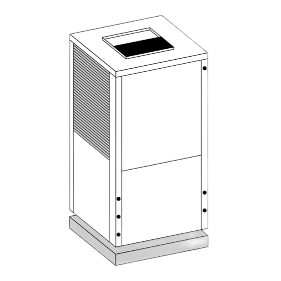
GO SERIES INITIAL INSPECTION: work gloves. Use a quenching cloth for brazing, and place a fire extinguisher close to the work area. Be certain to inspect all cartons or crates on each unit as received at the job site before signing the freight bill. LOCATION: Verify that all items have been received and that there are no visible damages;... -
Page 3: Condensate Drain
Refer horizontal unit. In this case the unit should be set in a full to the FHP individual data specification sheet for physical size secondary drain pan on top of a vibration absorbing dimensions of the collar and flange. -
Page 4: Electrical
GO SERIES Serious damage or erosion of the water to refrigerant provided in the control box and power leads to the power heat exchanger could occur. supply terminal block as indicated on the wiring diagram and Figure #5. A l w a y s c h e c k c a r e f u l l y f o r w a t e r l e a k s a n d r e p a i r appropriately. -
Page 5: Safety Devices & Lockout Circuit
(such as FHP’s part # 641-068), the unit thermostat connection block. If the motor ramps up to must be provided with a malfunction relay (FHP option # 100% power, then the motor itself is functioning normally. 660-006) to properly energize the light. The relay coil will Always remember to replace the jumper to NORM, (+) or be wired across the (ALR) and (C) contacts on the unit’s... -
Page 6: Electric Heater Package Option
GO SERIES (Figure #8) start-ups in the heating mode. After the 90 second period has elapsed, if the low pressure switch opens, the unit compressors will shut down. After the first shut down, the unit will restart once the switch(es) close and the anti short cycle timer has timed out. -
Page 7: Sequence Of Operation Single Step
GO SERIES Each Geo-Miser model has a number of heater sizes At this point the time delay relay starts timing out. Once a v a i l a b l e . R e f e r t o F i g u r e # 9 f o r h e a t e r p a c k a g e t h e t i m e p e r i o d s e t o n t h e T D R e l a p s e s , t h e 4 0 % c o m p a t i b i l i t y w i t h s p e c i f i c G e o - M i s e r u n i t s , m o d e l compressor restarts for full 100% capacity. -
Page 8: Well Water Systems
50˚ F to 100 ˚ F to assure adequate cooling and heating performance. Set timer to minimum In the cooling mode, heat is rejected from the FHP unit setting (0.03 Min) into the water loop. A cooling tower provides evaporative cooling to the loop water thus maintaining a constant supply temperature to the unit. - Page 9 GO SERIES (Figure #11) WELL WATER APPLICATIONS (50°F EWT MIN.) LINE VOLTAGE DISCONNECT (UNIT) FLEX DUCT CONNECTION LOW VOLTAGE CONTROL CONNECTION LINE VOLTAGE CONNECTION VIBRATION PAD P/T PORTS HOSE KITS (Optional) BALL VALVES SOLENOID VALVE SLOW CLOSING CONDENSATE DRAIN CONNECTION PRESSURE TANK (Optional) LINE VOLTAGE DISCONNECT (ELECTRIC HEATER) NOTE: SEE FIGURE #3 FOR CONDENSATE DRAIN CONNECTION...
-
Page 10: System Checkout
GO SERIES (Figure #13) EARTH COUPLED APPLICATION LINE VOLTAGE DISCONNECT (UNIT) FLEX DUCT CONNECTION LOW VOLTAGE CONTROL CONNECTION LINE VOLTAGE CONNECTION (UNIT) P/T PORTS VIBRATION PAD CONDENSATE DRAIN GROUND LOOP CONNECTION KIT (550-016, 017) GROUND LOOP PUMPING PACKAGE (GL001-1 or 002-1) 10. -
Page 11: Maintenance
GO SERIES MAINTENANCE: Lubrication of the blower motor is not required, h o w e v e r m a y b e p e r f o r m e d o n s o m e m o t o r s t o Filter changes or cleanings are required at regular extend motor life. - Page 12 GO SERIES (Figure #15)
- Page 13 GO SERIES (Figure #16)
-
Page 14: Trouble Shooting
GO SERIES TROUBLE SHOOTING POSSIBLE CAUSE CHECKS AND CORRECTIONS PROBLEM Power supply off Apply power, close disconnect. ENTIRE UNIT DOES NOT RUN Blown fuse Replace fuse or reset circuit breaker. Check for correct fuses. Broken or loose wires Replace or tighten the wires. Voltage supply low If voltage is below minimum voltage specified on unit data plate, contact local power company. -
Page 15: Unit Check Out
Serial Number _______________________________ Max Fuse Size (Amps) _____________________________ Volts / Amps_____________________ /____________________ Entering Air Temperature ___________________________ Leaving Air Temperature____________________________ FHP Manufacturing • 601 N.W. 65th Court • Fort Lauderdale, FL 33309 Phone: (954) 776-5471 • Fax: (800) 776-5529 • http://www.fhp-mfg.com... -
Page 16: Operating Pressures & Temperatures
GO SERIES GENERAL: There are many variables (airflow, air temperatures) in an air conditioning system that will affect operating refrigerant pressures and temperatures. The chart below shows approximate conditions and is based on air flow at the rated SCFM, entering air at 80˚ FDB, 67˚ FWB in cooling, 70˚... - Page 17 GO SERIES GENERAL: There are many variables (airflow, air temperatures) in an air conditioning system that will affect operating refrigerant pressures and temperatures. The chart below shows approximate conditions and is based on air flow at the rated SCFM, entering air at 80˚ FDB, 67˚ FWB in cooling, 70˚...
- Page 18 GO SERIES GENERAL: There are many variables (airflow, air temperatures) in an air conditioning system that will affect operating refrigerant pressures and temperatures. The chart below shows approximate conditions and is based on air flow at the rated SCFM, entering air at 80˚ FDB, 67˚ FWB in cooling, 70˚...
- Page 19 21-26 55-65 160-170 14-18 75-85 125-135 13-18 19-24 65-75 165-175 16-20 50˚ 10.0 75-85 120-130 8-12 20-25 65-75 165-175 17-21 GO072 80-90 148-157 13-17 18-23 75-85 175-185 6-10 17-22 60˚ 10.0 80-90 140-150 8-12 19-24 77-87 177-187 18-23 COMP. 85-95...
- Page 20 GO SERIES REV.12/01...
Need help?
Do you have a question about the GO072 and is the answer not in the manual?
Questions and answers