Table of Contents
Advertisement
Phone: +0011-1- 800-932-3030 Fax: +0011-1-360-757-7950
®
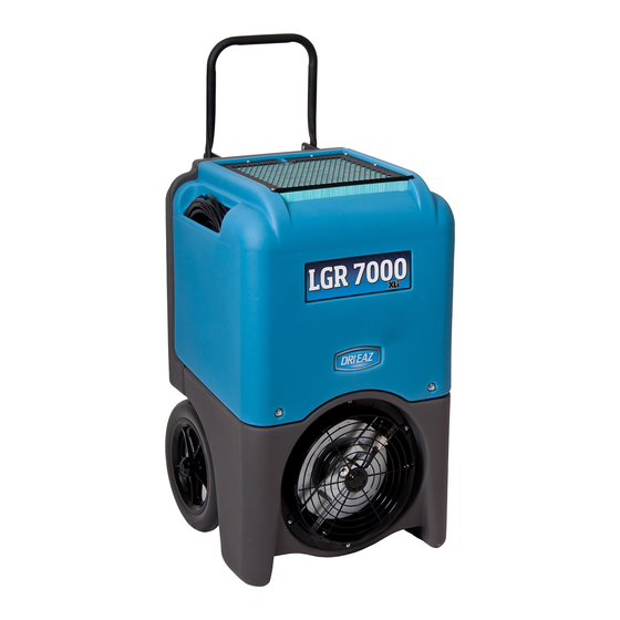
The Dri-Eaz
LGR 7000XLi dehumidifier reduces humidity in enclosed environments by
removing water vapor from the air. The 7000XLi is rugged, durable and highly portable, making
it ideal for water damage restoration, structural drying, construction, and other applications
requiring temporary, high-performance dehumidification.
R E A D A N D S A V E T H E S E I N S T R U C T I O N S
SAFETY INSTRUCTIONS
WARNING
WARNING! Do not alter or modify your LGR 7000XLi
in any way. Use only replacement parts authorized
by Dri-Eaz Products, Inc. Modifications or use of
unapproved parts could create a hazard and will
void your warranty. Contact your authorized Dri-Eaz
distributor for assistance.
WARNING! Electric shock, rotating fan, and hot
surface hazards. Unplug unit before opening cover
for cleaning or servicing. Unit must be grounded.
• Inspect the power cord before use. If cord is
damaged, do not use. Always grasp the plug (not
the cord) to unplug.
• Insert power cord into a matching electrically
grounded outlet. Do not use adapter. Never cut off
third prong. Do not use an extension cord.
• The unit must be operated on a 230V/50 Hz circuit.
• Do not operate unit in standing water. Keep motor
and wiring dry.
• If the supply cord is damaged, it must be replaced
by the manufacturer, its service agent or similarly
qualified persons in order to avoid a hazard.
WARNING! Do not alter or modify your LGR 7000XLi
in any way. Use only replacement parts authorized
by Dri-Eaz Products, Inc. Modifications or use of
unapproved parts could create a hazard and will
void your warranty. Contact your authorized Dri-Eaz
distributor for assistance.
07-01802C (F412-230V) 2013-01 Warranty 07-00427
Owner's Manual
LGR 7000XLi Portable Dehumidifier
Original Instructions • Models F412-230V
DRI-EAZ PRODUCTS, INC.
15180 Josh Wilson Road, Burlington, WA 98233
Patents: http://www.LBpatents.com
http://www.drieaz.com
CONTENTS GUIDE
OPERATIONS
Parts identification .......................................... 2
Positioning a dehumidifier ............................. 2
Operating your dehumidifier .......................... 2
Control Panel Guide ........................................ 3
At the end of the job ........................................ 4
Setting humidistat mode ................................. 4
MAINTENANCE
Maintenance schedule .................................... 7
Cleaning the coils and block .......................... 7
Cleaning the pump valve .............................. 11
Inspecting the Control Panel ........................ 16
Error messages ............................................. 17
Troubleshooting ............................................ 18
BEFORE YOU BEGIN
Warranty registration
Visit warranty.drieaz.com to register your purchase.
Registration allows us to better assist you with using,
maintaining or servicing your equipment, as well as to
contact you in case we have important safety information
concerning your Dri-Eaz product. If you determine
service is required, have your equipment model, serial
number and original proof of purchase available and call
your distributor for assistance with obtaining a return
material authorization (RMA).
INTRODUCTION
Dri-Eaz dehumidifiers reduce humidity in enclosed
structural environments by removing water vapor from
the air.
LGR (low-grain refrigerant) dehumidifiers like the
7000XLi utilize a pre-cooling system to boost water
removal efficiency. LGR units can continue to remove
moisture in drier environments where conventional
refrigerants cannot.
1
Dri-Eaz Products, Inc.
Advertisement
Table of Contents

Related Manuals for Drieaz LGR 7000XLI


Summary of Contents for Drieaz LGR 7000XLI
-
Page 1: Table Of Contents
Phone: +0011-1- 800-932-3030 Fax: +0011-1-360-757-7950 ® The Dri-Eaz LGR 7000XLi dehumidifier reduces humidity in enclosed environments by removing water vapor from the air. The 7000XLi is rugged, durable and highly portable, making it ideal for water damage restoration, structural drying, construction, and other applications requiring temporary, high-performance dehumidification. -
Page 2: Parts Identification
PARTS IDENTIFICATION FIG. A: FRONT FIG. B: REAR Integrated handle. Folds for storage. Drain hose pocket. Humid air inlet. 3M™ HAF filter. Molded pocket for cord storage. Control panel. Process (dehumidified) Drain hose location. air outlet. May be used with standard 12 in. rigid or layflat ducting. -
Page 3: Control Panel Guide
NOTICE: Uncoil and straighten the entire drain hose. Do below). The second line of the display alternates not leave any part of the hose coiled on the unit and do between inlet temperature and inlet humidity. not place the end of the hose higher than 6 m above the User Settings Menu bottom of the unit. -
Page 4: At The End Of The Job
displays. This is part of the unit’s self-diagnosis procedure and no user intervention is required. Humidistat Mode Once the self-diagnosis is complete, the display will show the following information: HUMIDISTAT MODE UNIT ON 00 HRS ON/OFF > INLET 00°C / INLET 00% In ON mode, unit will maintain the humidistat setpoint (see below). - Page 5 Special Tip: Before transporting unit on stairs, follow these additional steps to ensure that all water is removed from the unit: 1. Turn the unit off after a defrost cycle has been completed. Gently rock the upright machine on its wheels to ensure any water remaining on interior surfaces falls into the sump area.
- Page 6 FIG. D: PARTS DIAGRAM HAF filter Sensor chip. Lead cable (not shown) is attached to back of control panel. Cover Heat exchange block. Control panel Condenser (hot) coil Rear panel ⅜ in. rear panel Evaporator (cold) coil fasteners (×6) ⅜ in.
-
Page 7: Maintenance Schedule
may damage the filter. MAINTENANCE SCHEDULE NOTICE: Replace used filters only with a new HAF filter WARNING! ELECTRIC SHOCK HAZARD. Unplug the (Dri-Eaz part no. F368). Other filter types do not provide dehumidifier before performing any maintenance. adequate filtration or airflow. Be sure to install the new WARNING: Risk of dust and contaminants exposure. - Page 8 Installing the HAF filter To protect your HAF Filter from damage, make sure you insert the filter in the correct orientation. CORRECT. INCORRECT. Filter plies are in Filter plies are set line with direction 90 to direction of of insertion. insertion.
- Page 9 Lift off front cover and set aside. Disconnect the sensor chip assembly from the block. Gently lift the chip and the mounting post together out of the block. NOTICE! The sensor chip assembly is fragile. Handle with care at all times. To avoid damaging the sensor with a static electricity discharge, do not touch the sensor circuitry, and do not place any tape or other material in contact with the sensor circuitry.
- Page 10 Inspect the heat exchange block carefully. If dust is present, use compressed air or a HEPA-filtered vacuum cleaner to gently clear the channels of the block. Inspect the vertical condenser (hot) coil. If dust is present, vacuum or use compressed air on both sides of the coil until it is clean.
-
Page 11: Cleaning The Pump Valve
Replace the sensor chip assembly in to the heat exchange block. NOTICE! The sensor chip assembly is fragile. Handle with care at all times. To avoid damaging the sensor with a static electricity discharge, do not touch the sensor circuitry, and do not place any tape or other material in contact with the sensor circuitry. - Page 12 Stand the unit upright and remove the front cover as described under “To disassemble the unit for cleaning coils and heat exchange block,” p. 8. ∕ Now remove the four rear panel in. bolts. Tip the top of the rear panel away from the unit and lay it flat in front of the unit.
- Page 13 Clean and inspect the the pump check valve. First, use needle-nosed pliers to remove the pumpout hose from the barbed fitting on the pump. Tuck the hose inside the back cover housing. ∕ Remove the two in. bolts securing the pump mounting bracket.
- Page 14 ∕ Clean and inspect the check valve. Using a in. wrench or adjustable end wrench, unthread the check valve fitting and remove it from the pump. Using small-jawed pliers, carefully remove the valve compression fitting and the “duckbill” valve. Rinse all three items in clean water. Reassemble the check valve components in the sequence shown.
- Page 15 Reassembling pump and back cover Reinstall pump. Slide pump and pump bracket back into place. Ensure that the two holes in the bracket, the rotomolded housing and the pump basin are properly aligned before inserting and starting the bolts by hand. ∕...
-
Page 16: Inspecting The Control Panel
INSPECTING THE CONTROL PANEL Using a Philips screwdriver, remove the four baseplate retaining screws. Carefully lift out the control panel. The sensor connections are located on the underside of the panel. The sensor connections are labeled “OUT T” (outlet temperature sensor) and “DEFR” (defrost sensor). Note that the DEFR cable is marked with silver paint. -
Page 17: Error Messages
ERROR MESSAGES The LGR 7000XLi control system constantly monitors internal operating conditions. If the system detects an problem, it will produce an error (“ER”) message indicating the problem. If the display shows an ER message, first unplug the unit and then plug it back in. This will usually reset the electronics, and the unit will begin operating normally. If the error message reappears, refer to the explanation and solution shown below. -
Page 18: Troubleshooting
Service Department toll-free at 800-932-3030 for further assistance. SPECIFICATIONS Warranty information is available at www.dri-eaz.com. LGR 7000XLi Be sure to visit warranty.drieaz.com and register your Model F412-230V, F412-230V AU, purchase. Your registration will help us provide you with F412-230V HE updated product information as needed. -
Page 19: Electrical Schematic
ELECTRICAL SCHEMATIC 07-01802C (F412-230V) 2013-01 Warranty 07-00427 Dri-Eaz Products, Inc.
Need help?
Do you have a question about the LGR 7000XLI and is the answer not in the manual?
Questions and answers