
Related Manuals for Caminetti Montegrappa LIGHT 06


Summary of Contents for Caminetti Montegrappa LIGHT 06
- Page 1 DIRECTIONS FOR INSTALLATION USE AND MAINTENANCE LIGHT series LIGHT 06 NATURAL CONVECTION CLOSED FIREPLACE Serial Number...
- Page 2 Some measurements may be in Metric. Here forward, Caminetti Montegrappa, Fiamma llc, Caminetti Montegrappa USA may be referred to as Caminetti Montegrappa and any disclaimer applies to all. Before installing and operating your appliance, read this instruction manual carefully and save it for future reference.
- Page 3 Warranty void if the unit is not used in accordance with the operation and maintenance instructions. Keram re® is a material resulted from Caminetti Montegrappa research to obtain the best performance from your appliance; manufactured from natural raw materials, it withstands very high temperatures and thermal shocks and can absorb and store heat, radiating it for hours after the re has gone out.
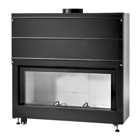
- Page 4 Sizes have been converted from Metric, Inches are rounded off. LIGHT 06 52.75" 21" 8" 10" 53.25 55.50" 19" 9.25" 6" 12.60" 21" 4.75 15.75" 57.50" 41" 4.75" 2.75" 47.25" 25" 52.75" LIGHT 06 See Data Tag for required info.
- Page 5 SOFTWOOD = kcal/kg 2800 - 3400 understand the importance that Caminetti Montegrappa gives HARDWOOD = kcal/kg 3400 - 3900 to the selection and preparation of the fuel, and the correct...
- Page 6 preliminary wood drying; rewood you have purchased has been seasoned for about covering the upper part of wood piles with clothes as shelf one year, you should always buy your rewood in the from the rain; summertime (June-July) since trees are mostly cut in cutting of the wood logs into small pieces whose length autumn.
- Page 7 Your Dealer for a new copy. on it. Do not modify or replace any parts in the unit by yourself; not-authorized works may cause injuries and will relieve Fiamma Llc. and Caminetti Montegrappa of any public or criminal liability. During operation, some of the appliance surface areas may become very hot;...
- Page 8 1.6 Safety requirements and 1.7 Environment requirements devices the snap closure of the door folding into the frame when it stops and the special gaskets the door incorporates make the rebox totally air-tight if compared to The air supply must be su cient for both proper one without this device.
- Page 9 1.8 Equipment 1.8.1 x 1 6204004400 x 2 1184167801 x 1 1102047230 x 1 1105903309 x 1 0920000440 LIGHT series...
- Page 10 1.8.2 (code 1530200100 optional available on price list) UNI 5448 A M5 RP UNI 6592 M5 x 4 1102011000 12 x x 12 1012000400 TCC UNI 7049 3,5x9,5 x 6 1509090000 x 3 1502010000 x 1 1502010100 x 2 1263000900 x 2 1184065600 x 1 1184965809 x 1 1280370800...
- Page 11 1.8.4 1184966109 EXAMPLE OF INSTALLATION WITH 1280370800 1 x 1263000300 (x Ø 15 cm) 1 x 1184966109 1 x 1280370800 NOT INCLUDED x 1 1189101401 x 4 1012010000 x 2 1509090000 x 1 1502090100 x 1 1505990009 x 1 1263001100 2 5 c 1263000300 TCC FOR UNI 8118 4,2x16...
- Page 12 1.8.5 (code 1530500X00 optional available on price list) 1530500000 (LIGHT 06) MOD. LIGHT 06 170 cm* 72 cm 120 cm 48 cm * +10 cm with cod. 1530901000 +20 cm with cod. 1530901000 + cod. 1530902000 x 1 1530500100 x 1 1530500200...
- Page 13 1.8.6 (code 1530901000 optional available on price list) PROGRAMMING OF CONTROL UNIT’S SWITCHES LEFT/RIGHT-HAND SIDE OFF* OFF* APPLIANCE MOD. OFF* OFF* BEEP TONE OFF* OFF* AUTOMATIC SLIDING SYSTEM * see section 2.3.5. Provide for RIGHT-HAND SIDE a lateral door 20x16 cm or frontal 16x16 cm 1 5 ,...
- Page 14 1.8.7 (code 1530902000 optional available on price list) FOR INSTALLATION WITH 1530901000 LEFT-HAND SIDE RIGHT-HAND SIDE Provide for - 8 6 - 8 6 a lateral door c a . c a . 20x16 cm or frontal 16x16 cm 2 5 c 2 5 c TCC UNI 7049 4,2x13 4 , 5...
- Page 15 1.9 Functioning principle The shape and the Keram re® lining of the combustion chamber allow to reach and retain high temperatures inside of it, thus maximizing the combustion phases with consequential reduction in the amount of the fuel needed. Thanks to its position (top of combustion chamber) and shape, the “...
-
Page 16: Installation Requirements
INSTALLATION 2.1 Packaging dismantling and 2.3.1 disposal Consisting of non-toxic and not noxious materials, the If the appliance needs to be installed in locations with limited packaging does not need any special disposal procedure; the access (for example, in upper oors or basements, and thus user is in charge of stocking, disposing of, or recycling the accessible only through stairways), it is possible to lighten wastes of the packaging according to the regulations in force... - Page 17 2.3.3 First try your appliance in place in order to determine where to make the connection between the appliance and the chimney ue; determine the position of the outside air intakes and provide the insulation on the adjacent walls; remove the appliance from the location before making the necessary openings on the exterior wall;...
- Page 18 Place the switch on “on” if the appliance is LIGHT 01 or LIGHT 03; leave it on “o ” if it is LIGHT 02 or LIGHT 06. − Switch Nr. 3: it activates or deactivates the beep tone of the end of stroke.
- Page 19 This procedure is to be carried out only the rst time to con gurate the radio control with the electrical sliding motor. To con gurate the radio control with the electrical motor of the sliding door proceed as follows: − feed the electrical motor through the bipolar switch properly arranged, −...
- Page 20 If necessary, it is possible to lower the “electrical sliding motor kit” approx. 86 cm, using the “transmission kit for electrical sliding mechanismus” (code 1530902000 optional, available on price list) as follows: − the transmission kit [R] is supplied for installatin on the left- hand side of the appliance, if it needs to be installed on the right-hand side, the two clamps [S] have to be removed and xed on the opposite side using the 8 screws supplied,...
- Page 21 2.3.6 Make two holes in the wall communicating with the outdoors (or with a su ciently aerated room) suitable for feeding the relevant exible aluminium pipe Ø 8 cm and another of Ø 15 cm inside the drywall panel (see gure 3). Once the appliance has been positioned correctly as just The standards currently in force require that all appliances described, insert the collector into the section of exible...
- Page 22 2.3.7 least 20 mm); the interior section must be invariable, free from constrictions For the connection of the unit to the chimney ue, use only and independent. non-combustible elements suitable to resist to the combustion A cleanout opening with a tight tting lid under the products and to the condensate (creosote) build-up.
- Page 23 2.3.9 the roof; therefore it is necessary to comply with the required minimum heights in the gure below; in case there are two or more adjacent chimneys, the one The good draught of the chimney ue also depends on the type of terminal covering the top of the chimney, which must which exhausts from a solid fuel appliance or which serves an comply with the following requirements:...
- Page 24 (room air entering through openings provided on our factory-built claddings) Measument of hole to be made on the Insulating panel - dim. 90x50 cm - min. thickness 2,5 cm (LIGHT 06) drywall panel (see instructions on our frames or claddings)
- Page 25 2.3.13 2.3.12 We recommend the use of 1/2 - thick reproof Cement board panels for building the nishing mantle or drywall panel, supported by a skeleton of galvanised sections duly anchored to the walls, ceiling and cladding mantelshelf. Use a 17 mm spanner (wrench) to level the appliance on its adjustable feet.
- Page 26 2.3.14 1. When building the nishing mantle or drywall panel in plasterboard, make an opening of 82,5x9,5 cm, 200 cm o the oor. Insert the two unions [A] in the exible aluminium pipes [B], already connected in advance on the rear openings of the appliance and secure them with pipe collars [C].
- Page 27 3. Put a hand in the central part of the long hopper [D] and get hold of the two unions [A] and: - insert the threaded pin [A1] of the union [A] in the hole of Ø 5 mm [D1] of the long hopper [D], then first insert the washer [E] and then screw the winged nut M5 slightly [F];...
- Page 28 OPERATION 3.1 Pre- and rst-lighting instructions Before lighting the appliance for the rst time the following must be provided: remove the sticker from the glass and any adhesive marks if necessary; It may seem easy to light a re in a wood-burning appliance ensure that all safety requirements are met (see sections 1.5 but it actually is not.
- Page 29 that a single piece of wood hardly burns. Never place the rewood pieces too close to one another in order to avoid starving the re of oxygen; never overload your appliance by placing more wood than the required optimum quantity (see section 1.3). A small re receives more oxygen, burns better and produces more heat than a bulk re, which chokes the the rebox;...
-
Page 30: Care And Maintenance
CARE AND MAINTENANCE 4.1 Routine inspection and cleaning good rule never to remove cinders using a vacuum cleaner and to throw them in a metal container, where they can cool down completely before throwing them away for good. Do not forget that performing the following routine inspection and cleaning will ensure your appliance e ciency and proper operation for a long time. - Page 31 3° outlet and remove any ashes and soot accumulated on its walls during the burning process. LIGHT 06 LIGHT series...
- Page 32 4.2.2 appliance or the reverse; check to see if the exhaust system (pipe and chimney ue) is Even with the best appliances and chimneys the formation of air-tight or needs to be cleaned out; creosote deposits is unavoidable. make sure that there is a good connection between the Therefore it is necessary to clean the chimney and the vertical appliance and the chimney ue;...
- Page 33 5.2 Servicing record DATE SERVICE DESCRIPTION SIGNATURE OF SERVICING STAFF DATE SERVICE DESCRIPTION SIGNATURE OF SERVICING STAFF DATE SERVICE DESCRIPTION SIGNATURE OF SERVICING STAFF DATE SERVICE DESCRIPTION SIGNATURE OF SERVICING STAFF DATE SERVICE DESCRIPTION SIGNATURE OF SERVICING STAFF DATE SERVICE DESCRIPTION SIGNATURE OF SERVICING STAFF LIGHT series...
- Page 34 Woodbury CT 06798 203-266-7717 The Company Here known as: Caminetti Montegrappa, Caminetti Montegrappa USA, Fiamma Llc. reserves the right to make any alterations resulting from any technical or commercial reasons it considers appropri ate without notice and assumes no responsibility for any possible mistake or inaccurancy in this brochure.
Need help?
Do you have a question about the LIGHT 06 and is the answer not in the manual?
Questions and answers