Table of Contents
Advertisement
Quick Links
Attention
Adjust the black-balance setting when using the unit for the first time. (Refer to page 50)
Set VF TYPE on the <SYSTEM MODE> screen on the SYSTEM SETTING page depending on your viewfinder. The
factory setting is set to the HD viewfinder.
Consult the dealer for installation of the AVC-Intra codec board (AJ-YBX200G).
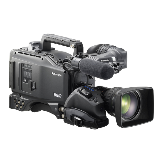
AJ-HPX2000 integrates a camera unit equipped with three CCDs, incorporating a 2/3-inch on-chip lens featuring
progressive drive technology (All-pixel reading), and a video recorder/player (VTR) that supports DVCPRO HD,
DVCPRO50, DVCPRO and DV formats.
AJ-HPX2000 offers choices of 1080i/720P mode for HD and NTSC/PAL mode for SD. It also provides features such as
storage-type gain enhancement for news reports and film-like gammas for production purposes, providing many
applications ranging from news reports to production.
Utilising P2 cards, which require no mechanism, as media, your unit offers greater responsibility, operability, and
portability. It is highly resistant to shock and vibration during recording, and therefore ensures stable operation for
capturing quality video images under the most adverse conditions.
_ Supports the new AVC-Intra codec (optional)
Installation of the AVC-Intra codec board (AJ-YBX200G)
provides support for the new AVC-Intra codec. By
employing the Intra-Frame compression method based
on
H.264
standards,
compression technology, a high compression rate, high
image quality, and high editing accuracy have been
achieved.
The AVC-Intra codec supports the following two
methods.
High image quality supporting full sample HD :
AVC-Intra100
Capable of operation at low rates and low cost:
AVC-Intra50
_ Supports the HD/SD multi format
System frequency
59.94 Hz/50 Hz switchable
HD
DVCPRO HD/AVC-Intra100/AVC-Intra50
1
switchable *
SD
DVCPRO50/DVCPRO/DV switchable
In the HD (1080i and 720P) mode, the new AVC-Intra
codec (optional) can be selected as the recording format
in addition to the ordinary DVCPRO HD.
In SD mode, you can select a recording format
appropriate for your purpose. For example, choose
DVCPRO50 to give higher priority to image quality or
DVCPRO if cost efficiency is a high priority.
*1 When the AVC-Intra codec board (AJ-YBX200G) is
installed
General
the
latest
motion
picture
_ 24P, 30P, 25P Recording and Native Recording
The unit is capable of recording at frame rates of 24P
(23.98P)/30P (29.97P) at 59.94 Hz and 25P at 50 Hz
using the progressive drive of the CCD.
There
are
two
methods:
2
recording)*
records images at the unchanged frame
rate of the camera, and the other method*
down to 59.94 or 50 frames.
*2 For the AVC-Intra100/50 at 1080i, AVC-Intra100/50
at 720P, and the DVCPRO HD formats, the rate is
pulled down to 59.94 or 50 frames during playback.
*3 For the (HD) DVCPRO HD, (SD) DVCPRO50,
DVCPRO, and DV formats
one
method
(Native
3
pulls the rate
7
General :
Advertisement
Table of Contents

Related Manuals for Panasonic AJ-HPX2000


Summary of Contents for Panasonic AJ-HPX2000
- Page 1 (All-pixel reading), and a video recorder/player (VTR) that supports DVCPRO HD, DVCPRO50, DVCPRO and DV formats. AJ-HPX2000 offers choices of 1080i/720P mode for HD and NTSC/PAL mode for SD. It also provides features such as storage-type gain enhancement for news reports and film-like gammas for production purposes, providing many applications ranging from news reports to production.
- Page 2 _ Multi-format Mode SYSTEM MODE Recording method 59.94i AVC-Intra100* 29.97P (Native) AVC-Intra50* 23.98P (Native) 1080-59.94i 59.94i 29.97P Over 59.94i DVCPRO HD 23.98P Over 59.94i (2-3 Pull-down) 23.98P Over 59.94i (2-3-3-2 Pull-down) 59.94P AVC-Intra100* 29.97P (Native) AVC-Intra50* 23.98P (Native) 59.94P 720-59.94P 29.97P (Native) DVCPRO HD 29.97P Over 59.94P...
- Page 3 Features of Recorder/player unit _ Multiple Slots _ 4-channel Digital Audio Recording (all formats) AJ-HPX2000 is equipped with five slots for P2 cards. Up In HD (1080i or 720P) mode, 4-channel digital audio to five cards may be inserted in these slots for recording is used.
-
Page 4: Recording Time
5 minutes AVC-Intra100* _ Recording Time AVC-Intra50* Approx. 10 minutes DVCPRO50 Operation of the following P2 cards with AJ-HPX2000 has been verified: DVCPRO Approx. AJ-P2C004HG (4 GB) 20 minutes AJ-P2C008HG (8 GB) *1 When the AVC-Intra codec board (AJ-YBX200G) is installed... - Page 5 By connecting with a PC via USB2.0, a P2 card inserted (when the AJ-YA350AG is attached) in AJ-HPX2000 can be used as a bulk storage device. The camera-recorder with the AJ-YA350AG extension It is also possible to store data on a P2 card onto a USB board attached can record SDI signals input through the 2.0-connected external hard disk equipped with USB...
- Page 6 Dimensions drawing Unit: mm (inch) 137 (5- ) 318 (12- ) General :Dimensions drawing...
- Page 7 Hard carrying case: AJ-P2C016RG AJ-HT901G SD Memory cards* AJ-P2C032RG For the latest information on P2 cards and SD memory cards not available in the operating Instructions, visit the P2 Support Desk at the following Web sites. https://eww.pavc.panasonic.co.jp/pro-av/ General :System Configuration...
-
Page 8: Recording And Playback
Recording and Playback P2 Cards Inserting P2 Cards Insert a P2 card into the P2 card slot until the EJECT button pops up. Note When using the camera-recorder for the first time, be sure to set the time data beforehand. On how the time data is set, see [ Setting Time Data ] (page 57). - Page 9 <For Your Information> Removing P2 Cards The P2 CARD ACCESS LEDs may be set to stay off using the menu option ACCESS LED. This option can be found While pressing down the slide lock button, move the on the <OPTION MODE> screen, which is accessible from slide-out door to the left.
- Page 10 P2 Viewer software. Download it from the following website. (Compatible with the Windows Vista, Windows XP and Windows 2000 operating systems.) https://eww.pavc.panasonic.co.jp/pro-av/ When using regular IT tools such as Microsoft Windows Explorer or Apple Finder to transfer data to a PC, follow the instructions below.
- Page 11 Basic Procedures This section describes the basic procedure for shooting Note that the recording order is retained even if the power and recording. Before you embark on a shoot, pre-inspect is turned off. When the power is next turned on, the last your system to ensure that it works properly.
- Page 12 Shooting White/Black balance adjustment to recording completion White/Black Balance Adjustment to Recording Comple- tion For shooting, follow the steps below. Select a filter according to light conditions. When the white balance is saved: Position the WHITE BAL switch to [A] or [B]. When the white or black balance is not saved and you have no time to adjust the white balance: Position the WHITE BAL switch to [PRST].
- Page 13 Normal Recording REC START/STOP button, REC button on the handle or VTR button at the lens starts recording of video and sound on the P2 card. A cluster of data that consists of video and sound generated through a shooting action, together with such added information as meta data, is called a “clip”.
- Page 14 Notes The recording will start from the top frame of a five-frame cycle for 24P/24PA recording, a four-frame cycle for 24P native recording or a two-frame cycle for 30P and 25P of 720P, respectively. Therefore, the time code may be discontinued when recording clips continuously in different modes during the recording cycle.
-
Page 15: Table Of Contents
Loop Recording When two or more P2 card slots contain cards, this Notes function allows the target P2 card to be switched in order. When the loop recording capability is used, each P2 Even when the free space of a P2 card is used up, this card must have at least one minute of free space. -
Page 16: The Handle, Or Vtr Button At The Lens
TOTAL REC TIME (Recording time on P2 card) To check the previous recording during a pause Press the RET button at the lens to put the AJ-HPX2000 into For continuous recording REC REVIEW mode. ONE SHOT operation continues after the REC REVIEW. - Page 17 If the power is turned off during recording The respective settings for SD CARD READ/WRITE, If the AJ-HPX2000 is turned off during interval recording, LENS FILE CARD R/W, READ USER DATA, and the video stored in memory is recorded onto the P2 card, READ FACTORY DATA cannot be executed.
- Page 18 ONE CLIP REC Function This function compiles multiple recordings into a combined Exiting ONE CLIP REC mode clip and does not isolate single recordings (from REC START to STOP) to single clips. Set the ONE CLIP REC MODE item to “OFF” in the Menu. REC Start REC Start REC Start...
- Page 19 (present as of Nov. 2009). Refer to the P2 support page from the following web site for the most recent information on software that has been confirmed to work with these types of clips. https://eww.pavc.panasonic.co.jp/pro-av/ Recording and Playback :ONE CLIP REC Function...
- Page 20 Recording Review Function When recording is paused, pressing the RET button automatically locates the last two seconds of video just recorded, and the viewfinder provides video playback. After playback, the camera-recorder is again ready to start recording. The picture location/playback duration can be increased to up to 10 seconds by continuously pressing the RET button.
- Page 21 Normal and Variable Speed Playback The PLAY/PAUSE button provides monochrome playback Notes through the viewfinder and color playback on the LCD The camera-recorder cannot play back clips where the monitor. A color video monitor connected to the VIDEO system mode differs. If this is the case, set the system OUT or MON OUT connector of camera-recorder also mode of camera-recorder to the format of the desired provides color playback.
- Page 22 SHOT MARK button Recording Setting and Operation Mode AJ-HPX2000 recording mode works according to the priorities outlined in the following table, relative to the setting of the menus and switches. Menu switches related to system/recording Buttons...
-
Page 23: Lamps In The Viewfinder Screen
Viewfinder Screen Status Displays In addition to video images, the viewfinder displays lamps and text that indicate the settings and operating status of the unit, together with messages, a center marker, a safety zone marker and the camera ID. Lamps in the Viewfinder Screen BATT (battery) Lamp This lamp starts blinking a few minutes before the battery charge starts to run out, and stays illuminated... -
Page 24: Selecting Viewfinder Display Information
Selecting Viewfinder Display Information To select the information items you want to have displayed in the viewfinder screen, go to the <VF INDICATOR1> and # < VF INDICATOR2 > <VF INDICATOR2> screens from the VF page, and turn on P2CARD REMAIN :TOTAL BATTERY or off the appropriate options, or specify desired values. -
Page 25: 25P (Pull Down)
Information Item Indication Status This indicates the mode that the unit operates in. 1. System mode 1080 1080 interlace mode 720 progressive mode 480 interlace mode 576 interlace mode This indicates the video system when signals output from CCD are 2. - Page 26 Information Item Indication Status LOW/MID/HIGH Value set for the master gain 10. MODE CHECK –3 to 30 Example: LOW: 0 Indication Area S.GAIN 30/36/42/48 Gain value to which S.GAIN and DS.GAIN are assigned (STATUS: 6 : /10 : /12 : / DS.GAIN Master gain, 15 : /20 :...
- Page 27 Information Item Indication Status AWB A ACTIVE AWB being performed on Ch A. 11. Camera Warning and AWB B ACTIVE AWB being performed on Ch B. Report Area AWB A OK ¢ . ¢ K AWB successful on Ch A. (related to AWB, ABB AWB B OK ¢...
- Page 28 This is displayed when shot marks cannot be added. UPDATING Clip information is being updated. Playback operation disabled. USB DEVICE AJ-HPX2000 is in USB DEVICE mode. When communication is disabled, the indication blinks. USB HOST Indicates that the camera-recorder is set to the USB HOST mode. When the external hard disk is not successfully recognized, then the indication blinks.
- Page 29 Information Item Indication Status 14. Time code indication TCG 12:59:59:20 TCG (time code generator value) 12:59:59:20 TCR (time code reader value) (V)UBG AB CD EF 00 UBG VUBG (User bits generator value) (V)UBR 12 34 56 78 UBR VUBR (User bits reader value) –1:59:59:20 Displays CTL count.
- Page 30 Information Item Indication Status Displayed before and after operation during INTERVAL REC mode. 30. INTERVAL REC/PRE (blink) Displayed during INTERVAL REC operation. RECORDING (blink) ¢¢h¢¢m/¢¢s Displays the pause time before the next recording during INTERVAL REC. information display P-REC (blink) Displayed until images/audio are completely recorded to the P2 card after stopping recording.
- Page 31 Indications Available in the Viewfinder Screen Selectable Provided when between on and the appropriate Provided during Provided during Selectable off through menu status is MODE CHECK* playback options encountered. 1. System mode – – ⃝ ● ⃝ 2. Camera mode –...
- Page 32 Display Modes and Setting Changes/adjustment Result Messages The messages that appear on the viewfinder screen to # < VF DISPLAY > indicate changes to settings and adjustment results may DISP CONDITION :NORMAL be limited, or set not to appear, through the menu option DISP MODE VF OUT DISP MODE.
-
Page 33: Setting The Marker Displays
Setting the Marker Displays The center, safety zone, safety zone area and frame Note markers may be set to ON or OFF, along with The indication MKR:A at the upper right of the screen specifications of the marker types. To set and select shows the current indication status. - Page 34 Manipulating Clips with Thumbnails Playback, delete, copy or restore the clip. A clip is a data group that includes the images and voices Add or delete a shot mark and a text memo on the clip created from one shooting session, together with thumbnail.
- Page 35 Thumbnail Screen Press the THUMBNAIL button to display the thumbnail Display Mode screen on the LCD monitor. Pressing the THUMBNAIL The type of the thumbnail indicated on the display and button again returns the display to the regular display. the types of the other information screens are When switching is done from the regular screen display to indicated.
- Page 36 Recording mode Edit Copied Clip Indicator The recording mode for the clip on which the pointer is This marker is displayed on a clip when the model located is indicated. supports edit copy, such as the AJ-HPM100. For more information about edit copying, see the instruction System format manual for a mode that supports edit copying.
- Page 37 Selecting Thumbnails Multiple thumbnails can be randomly selected in the thumbnail screen. Use the cursor buttons to move the pointer (yellow frame) to the desired clip and press the SET button. The frame around the selected thumbnail changes to a blue frame. Press the SET button again to deselect the clip.
- Page 38 Switching the Thumbnail Display The display can be switched so that only those clips matching the specified conditions are displayed in the thumbnail screen. Press the THUMBNAIL button. Select THUMBNAIL from the thumbnail menu. Switch the thumbnail display by selecting one of the following The thumbnail screen appears on the LCD monitor.
-
Page 39: Changing Thumbnails
Changing thumbnails It is possible to replace thumbnails with images that include previously attached text memos while images are recorded or played back. Add text memos to images that you intend to change. Refer to [ Text Memo Function ] (page 42) for the method to add text memos. - Page 40 Shot Mark A shot mark can be added to a clip thumbnail to distinguish this clip from the others. Press the THUMBNAIL button. The thumbnail screen appears on the LCD monitor. Use the cursor buttons to move the pointer over the clip to which you want to attach a shot mark.
-
Page 41: Deleting A Text Memo
Playing back a clip at the position where a text memo is recorded Press the THUMBNAIL button. Move the pointer over the clip that contains the The thumbnail screen appears on the LCD monitor. desired text memo to playback and press the SET button. - Page 42 Using a text memo to break a clip and copy the necessary portion Select a desired text memo in a clip by carrying out User the cursor buttons and SET buttons to select the steps for [ Playing back a clip at the position where destination slot.
- Page 43 Reconnection of Incomplete Clips Incomplete clips may be generated when clips recorded on Press the THUMBNAIL MENU button and select multiple P2 cards (connected clips) are separately copied OPERATION > RE-CONNECTION from the to different cards. Reconnection function generates one thumbnail menu.
- Page 44 SD memory cards using a PC. Download the latest update version of P2 viewer from the following URL and install it to your PC: https://eww.pavc.panasonic.co.jp/pro-av/ Manipulating Clips with Thumbnails : Setting of Clip Meta Data...
- Page 45 PERSON or OFFSET. the setting. Note AJ-HPX2000 only displays printable ASCII characters. Checking and modifying read metadata The camera-recorder allows you to check the details of read metadata.
- Page 46 Japanese or Chinese characters indicated in English or other characters that cannot be indicated in English will not display properly; they will be indicated as ¢ . The letters which can be input with AJ-HPX2000 are only the alphanumeric. AJ-HPX2000 cannot input Japanese and Chinese.
- Page 47 [ Video Encoder Card Status Display (optional) ] (page 130). For instructions on updating, refer to the P2 support page on the following website. https://eww.pavc.panasonic.co.jp/pro-av/ Formatting a P2 Card Press the THUMBNAIL button. The following screen appears. Use the cursor buttons The thumbnail screen appears on the LCD monitor.
- Page 48 Formatting SD memory cards SD memory cards can also be formatted from the thumbnail screen. With an SD memory card inserted into the camera-recorder, perform the following operation: Press the THUMBNAIL button. The thumbnail screen appears on the LCD monitor. Press the THUMBNAIL MENU button and select OPERATION >...
- Page 49 Setting the Thumbnail Display Mode The thumbnail display mode can be customised to suit THUMBNAIL SIZE: your preferences. For the size of thumbnails displayed on one screen, either LARGE (3 a 2 thumbnails displayed) or NORMAL (4 a 3 thumbnails displayed) can be Press the THUMBNAIL button.
-
Page 50: Clip Property
SET Note button to check the detailed content. The underlined AJ-HPX2000 is not capable of recording or playing items are automatically set during shooting. For more back voice memos. information on displayed metadata, see [Setting of Clip Meta Data] (page 121). -
Page 51: P2 Card Status Display
Press the SET button. Press OK on the keyboard to write the modified meta- The input window (soft keyboard) for modifying meta- data on the clip and return to the metadata window. data is displayed. Use the keyboard to modify the meta- The input window (soft keyboard) for modifying meta- data. - Page 52 Contents of P2 Card Status Display Settings From the thumbnail menu, select PROPERTY > CARD STATUS. The following screen appears. When “REMAIN” is selected: When “USED” is selected: Write-protect Mark Write-protect Mark mark appears if the P2 card is write-protected. mark appears if the P2 card is write-protected.
-
Page 53: Sd Memory Card Status Display
If this is the case, writing or reading will not be the remaining memory capacity exceeds 999 min, “999 successful. Format the card with the AJ-HPX2000. For min” is displayed. more on formatting SD memory cards, see [Formatting SD The remaining capacity is displayed only when set to memory cards] (page 125). - Page 54 Connection with external device Connection through the DVCPRO/DV connector Records of signals input to the DVCPRO/DV connector The following functions are not available. Refer to [32.DVCPRO/DV connector] (page 21) to PRE-RECORDING function Loop recording function connect the 1394 cable (DV cable). Interval recording function Ensure that the signal format of the target device One clip recording function...
- Page 55 External device control through DVCPRO/DV connection The DVCPRPO/DV connector can be connected with an Notes external device for recording backup copies to control the When the Fire Store FS-100 is used as external storage, start and stop of recording. the VITC UB MODE menu option on the TC/UB screen on the MAIN OPERATION page can be set to FRM.
- Page 56 Connection with external devices using the USB 2.0 port Connection with a PC in the USB DEVICE mode By connecting AJ-HPX2000 with an external PC using USB 2.0, the P2 card connected to AJ-HPX2000 can be used as a mass storage device.
-
Page 57: Usb Host Mode
USB HOST mode AJ-HPX2000 can be connected to a hard disc drive that supports USB 2.0 to store data from cards on it, view thumbnails for stored clips, and write data back to P2 cards. Switching to the USB HOST mode... - Page 58 PARTITION Viewing hard disc drive information This section indicates the type of the hard disc drive. You can view the information on the hard disc drive The available functions depend on the type of hard disc drive. connected via USB 2.0 with the following steps. HDD type Feature Available functions...
- Page 59 MODEL VERIFY This section indicates the model of the P2 card that This section indicates the verification setting and originally contained data on the partition. results at the time the data on the partition was recorded. Note ON:FINISHED : Press the cursor button (!) to switch to the PARTITION Verification was performed and the results agreed.
- Page 60 Writing data on a hard disc drive Writing data back to P2 cards You can select clips on the hard disc drive to be written Switch the mode to USB HOST. For more information, back to P2 cards. see [ Switching to the USB HOST mode ] (page 134). Switch the mode to USB HOST.
- Page 61 PC. By using the drive mount converter distributed on the following URL, the hard disk drive can be mounted in the designated folder when connected. https://eww.pavc.panasonic.co.jp/pro-av/ Connection with external device : Connection with external devices using the USB 2.0 port...
- Page 62 Connection using the SDI IN connector (when AJ-YA350AG attached) Confirm that the HD/SD-SDI input board (AJ- YA350AG: optional accessory) is attached to the unit and that the wires are connected properly. For details, refer to the installation manual for the AJ-YA350AG. Confirm that the connected device has the same signal format as camera-recorder.
-
Page 63: Maintenance And Inspections
Maintenance and Inspections Inspections Before Shooting Make sure you check that the system is operating normally before embarking on a shoot. We recommend using a color video monitor to check the image. Preparing for Inspections Mount a charged battery pack. Insert a P2 card into the card slot and close the slide cover. -
Page 64: Inspecting The Memory Recording Functions
Inspecting the Memory Recording Functions Make sure you successively carry out the inspections from 2. Inspecting the Audio Level Automatic Adjustment [1. Inspecting the P2 Card Recording] to [4. Inspecting the Set the AUDIO SELECT CH1 and CH2 switches to Earphone and Speaker]. -
Page 65: Cleaning Inside The Viewfinder
6. Inspection of the clock, time code, and user bits Set the TCG switch to [F-RUN]. Set the user’s bit as required. Check that the counter display number changes Please refer to [ Setting of the user bits ] (page 59) for regardless of recording status. -
Page 66: Connector Signals
Connector Signals Panasonic part number K1AY104J0001 Panasonic part number K1AA104H0038 DC IN DC OUT Maker part number HR10A-7R-4SC(73) HA16RX-4P ( SW1 ) Maker part number 1 GND (Hirose Denki) (Hirose Denki) R TALLY Connector at the cable side (Open collector) - Page 67 Panasonic part number K1AY110JA001 REMOTE Maker part number HR10A-10R-10SC(71) CAM DATA (H) Data from the camera to the remote control (H) (Hirose Denki) CAM DATA (C) Data from the camera to the remote control (C) Connector at the cable side...
- Page 68 Panasonic part number K1AY112JA001 LENS Maker part number HR10A-10R-12SC(71) RET-SW ON/OFF of the return video (Hirose Denki) RETURN ON: GND RETURN OFF: OPEN REC-START/STOP Control for recording start/stop +5 V START STOP START IRIS-AUTO ON/OFF of the forced iris servo SERVO ON: +5V±0.5V...
- Page 69 Panasonic part number K1GB25A00010 Unislot Interface Maker part number HDBB-25S(05) CH-1 SHIELD (Hirose Denki) CH-1 HOT Audio input from the wireless receiver: CH1 HOT CH-1 COLD Audio input from the wireless receiver: CH1 COLD +12V UNREG Power supply to the wireless receiver...
-
Page 70: Warning Description Tables
Warning System Warning Description Tables If a problem is detected immediately after the power is turned on, or during operation, this will be indicated by the WARNING lamp, lamps inside the viewfinder and a warning tone. Note The WARNING lamp has the highest priority, followed by the tally lamp, and then the warning tone. When multiple errors occur simultaneously a higher priority indication will be triggered. - Page 71 5. P2 Card Fully Recorded 8. Number of Clips Exceeded “00:00:00:11” appears in the time code Display window All 7 bar indicators for remaining MEDIA Display window display field. Even after recording is stopped, indication capacity start blinking. indication this display continues to blink until the next This lamp will illuminate continuously until an operation is performed.
- Page 72 10. 1394 Error 13. P2 Card Error The 1394 E- ¢¢ indicator in the display Displays “00:00:00:11” in the time code Display window Display window window blinks. For more information, see display. The window continues to flash until indication indication the next operation, even after stopping [ 1394 Error Codes ] (page 150).
-
Page 73: Error Codes
Error Codes The following error codes are displayed in the display window if an error occurs in the camera: Confirm the type of warning and refer to the details in the [ Warning Description Tables ] (page 147) for countermeasures. Code No. -
Page 74: Warning And Error Display For Thumbnail Operation And Usb Host Mode
Card Warning Code Indication in display Code No. Description Recording window The directory structure on the P2 card is not Operation continues. However, back up data E-70 supported. ([DIR NG CARD (Slot No.)] is on the P2 card as soon as possible, and A warning code blinks once indicated on the viewfinder.) format the card before using it again. - Page 75 Item Message Description Measure CANNOT CHANGE! [PERSON] will be entered while the text Enter [TEXT] before entering [PERSON]. memo is not available. Soft keyboard CANNOT SET! The entered value is incorrect. Change the value. INVALID VALUE! HDD CAPACITY Not enough space left on the hard disk. There is not enough space on the connected hard FULL! disk.
- Page 76 Menu Menu Configuration MENU USER MENU SYSTEM SETTING SYSTEM MODE MAIN MENU OPTION MODE PAINT RB GAIN CONTROL REC FUNCTION RGB BLACK CONTROL OUTPUT SEL OPTION MENU MATRIX DOWNCON SETTING OPTION COLOR CORRECTION LCD MONITOR LOW SETTING GENLOCK MID SETTING 1394 SETTING HIGH SETTING ADDITIONAL DTL...
- Page 77 USER MENU is factory-set. The menu can USER MENU: LIGHT button be configured to suit your preferences by specifying each option according to your purposes and frequency of use, through the <USER MENU SELECT> screen, which is accessible from the MAIN MENU page. For more information, see [ Selecting Options for USER MENU ] (page 156).
-
Page 78: Setting Menu Options
Setting Menu Options The menu options are set with the MENU and JOG dial Turn the JOG dial button to move the mark ( > ) to a buttons. desired option. Then, press the JOG dial button. The The menu comprises main menu, sub-menus and options value starts blinking. -
Page 79: Selecting Options For User Menu
Selecting Options for USER MENU Go to the USER MENU SELECT page from MAIN MENU. Then, open relevant options menu screens to select options to add to USER MENU. Only the selected options are displayed as options in USER MENU. For information about how to navigate this menu, see [ Setting Menu Options ] (page 155). -
Page 80: 720P
Menu Description Tables SYSTEM SETTING SYSTEM MODE Items/ Adjustable Items/ Adjustable Remarks Remarks Data Saved Range Data Saved Range SYSTEM 1080-59.94i For setting the system frequency and the ASPECT 16:9 Select the aspect ratio for recording. (In recording format of the unit. MODE 1080-50i SD mode only )... - Page 81 SYSTEM MODE Items/ Adjustable Items/ Adjustable Remarks Remarks Data Saved Range Data Saved Range Used to enable or disable the mode that Select whether or not to forcibly disable PC MODE SAVE SW allows the camera-recorder to be the audio output when the SAVE ON/ (AUD OUT) connected to a PC or an external hard OFF switch is set to [ON].
-
Page 82: May Vary With
REC FUNCTION Items/ Adjustable Items/ Adjustable Remarks Remarks Data Saved Range Data Saved Range INTERVAL Sets INTERVAL REC function. PRE REC 1SEC Set PRE RECORDING. ON: Uses internal memory to perform REC MODE ONE SHOT 1-15SEC: TIME interval recording. Set the length of time that can be 8SEC ONE SHOT: retrospectively recorded before the... - Page 83 Items/ Adjustable Items/ Adjustable Remarks Remarks Data Saved Range Data Saved Range Select the ONE CLIP REC mode. Select whether or not to output clip ONE CLIP THUMBNAIL REC MODE ON: Operate in ONE CLIP REC mode. thumbnails displayed on the LCD OFF: Do not operate in ONE CLIP REC monitor to the video output and monitor mode.
- Page 84 LCD MONITOR GENLOCK Items/ Adjustable Items/ Adjustable Remarks Remarks Data Saved Range Data Saved Range BRIGHTNESS –7 Adjust the LCD monitor brightness. GENLOCK Switch the camera synchronising signal. INT: Synchronise with the internal reference signal regardless of the reference signal input to the –...
- Page 85 1394 SETTING Items/ Adjustable Remarks Data Saved Range For selecting the channels for audio 1394 AUDIO CH1/CH2 signals output from the DVCPRO/DV CH3/CH4 connector when the camera-recorder is operating in DVCPRO or DV mode (for 480-59.94i or 576-50i only) Note When CH3/CH4 is selected, no sound is heard in the following outputs: EE output if the 25M REC CH SEL...
- Page 86 PAINT RB GAIN CONTROL RGB BLACK CONTROL Items/ Adjustable Items/ Adjustable Remarks Remarks Data Saved Range Data Saved Range R GAIN AWB –200 For setting the Rch gain when the MASTER PED –200 For setting the level of the master WHITE BAL switch is in the PRST pedestal.
- Page 87 MATRIX COLOR CORRECTION Items/ Adjustable Items/ Adjustable Remarks Remarks Data Saved Range Data Saved Range For selecting the color correction table For performing the color saturation MATRIX –63 for the linear matrix. correction of red. TABLE (SAT) S C U F R S C U F R MATRIX R-G –63...
- Page 88 LOW SETTING Items/ Adjustable Items/ Adjustable Remarks Remarks Data Saved Range Data Saved Range MASTER –3dB Select the master gain from –3, 0, 3, 6, For performing the hue correction for R(PHASE) –63 9, 12, 15, 18, 21, 24, 27, or 30dB. GAIN red.
- Page 89 MID SETTING HIGH SETTING Items/ Adjustable Items/ Adjustable Remarks Remarks Data Saved Range Data Saved Range Select the master gain from –3, 0, 3, 6, Select the master gain from –3, 0, 3, 6, MASTER –3dB MASTER –3dB 9, 12, 15, 18, 21, 24, 27, or 30dB. 9, 12, 15, 18, 21, 24, 27, or 30dB.
- Page 90 ADDITIONAL DTL Items/ Adjustable Remarks Data Saved Range KNEE APE For changing the detail level of the high brightness portion. S C U F R DTL GAIN(+) –31 Adjust the detail level toward + (upwards). S C U F R DTL GAIN(–) –31 Adjust the detail level toward the –...
- Page 91 SKIN TONE DTL Items/ Adjustable Remarks Data Saved Range For selecting the skin color table for SKIN TONE Q-WIDTH enabling the skin tone detail. I-WIDTH Y-MAX The skin color table is provided in the + direction SKIN TONE TABLE item. I-CENTER By enabling the skin tone detail, it is –...
- Page 92 KNEE/LEVEL GAMMA Items/ Adjustable Items/ Adjustable Remarks Remarks Data Saved Range Data Saved Range MASTER PED –200 Set the master pedestal. MASTER 0.30 Set the master gamma in 0.01% steps. GAMMA +015 0.45 S C U F R +200 S C U F R 0.75 MANUAL Set the mode when the AUTO KNEE...
- Page 93 CAMERA SETTING Items/ Adjustable Remarks Data Saved Range For switching ON/OFF of the detail DETAIL signals. S C U F R For specifying whether or not to enable 2D LPF or disable the 2-dimension LPF, which reduce the cross color (for the SD mode only).
- Page 94 VF DISPLAY ZEBRA Pattern Display Video Level ZEBRA 2 Items/ Adjustable Remarks Data Saved Range SPOT 109% DISP NORMAL NORMAL: Display status constantly. CONDITION HOLD HOLD: Display status only when the MODE CHECK switch is pressed. – C U F R Set the DISP MODE.
-
Page 95: Frame
VF MARKER VF USER BOX Items/ Adjustable Items/ Adjustable Remarks Remarks Data Saved Range Data Saved Range Select the VF MARKER setting table. For setting whether the user box is TABLE USER BOX First, select table A or B, then set the displayed in the viewfinder or not. - Page 96 VF INDICATOR1 VF INDICATOR2 Items/ Adjustable Items/ Adjustable Remarks Remarks Data Saved Range Data Saved Range EXTENDER For selecting ON or OFF for the P2CARD Select the indication mode for the P2 extender display. card’s remaining capacity. REMAIN ONE-CARD OFF: Disable the remaining capacity TOTAL –...
- Page 97 Items/ Adjustable Items/ Adjustable Remarks Remarks Data Saved Range Data Saved Range Select whether or not to enable “REC” For the setting to display the status REC STATUS ON P.ON IND indication in the viewfinder and on the screen immediately after turning on the LCD monitor during recording.
-
Page 98: Cam Operation
CAM OPERATION CAMERA ID SHUTTER SPEED Items/ Adjustable Items/ Adjustable Remarks Remarks Data Saved Range Data Saved Range ¢¢¢¢¢¢¢ Setting 1 for the CAMERA ID recorded SYNCHRO Allocate SYNCHRO SCAN as a shutter ¢¢¢ on color bars. Up to 10 characters are SCAN speed selectable by the shutter switch. - Page 99 SHUTTER SELECT Items/ Adjustable Items/ Adjustable Remarks Remarks Data Saved Range Data Saved Range For setting the shutter speed for For setting the shutter speed for POSITION1 POSITION5 POSITION 1. POSITION 5. 1/100 1/100 For 59.94 Hz For 59.94 Hz 1/120 1/120 1/250...
- Page 100 USER SW SW MODE Items/ Adjustable Items/ Adjustable Remarks Remarks Data Saved Range Data Saved Range USER MAIN Allocate the USER MAIN button. For RET SW R.REVIEW For setting the function when the USER descriptions of the functions, see button on the unit, to which the RET S.GAIN CAM RET [ Assigning Functions to USER MAIN,...
- Page 101 Items/ Adjustable Items/ Adjustable Remarks Remarks Data Saved Range Data Saved Range DS.GAIN OFF L/M/H For selecting the method used to AWB AREA For switching the detection area for release the digital super gain mode executing the automatic adjustment of DS.GAIN (cumulative gain).
- Page 102 USER SW GAIN LENS/IRIS Items/ Adjustable Items/ Adjustable Remarks Remarks Data Saved Range Data Saved Range ¢ S.GAIN Select whether or not to enable 30dB for A.IRIS LEVEL 000 Set the target value for auto iris. SUPER GAIN. 30 dB •...
-
Page 103: Main Operation
MAIN OPERATION BATTERY/P2CARD Items/ Adjustable Items/ Adjustable Remarks Remarks Data Saved Range Data Saved Range BATTERY PROPAC14 Select the battery to use. Remaining CARD NEAR Select whether or not to set the alarm to capacity detection is also performed beep for P2 CARD NEAR END ALARM. SELECT TRIMPAC14 END ALARM... - Page 104 BATTERY SETTING1 Items/ Adjustable Items/ Adjustable Remarks Remarks Data Saved Range Data Saved Range ¢ ¢ PROPAC14 Enable selection under BATTERY DIONIC160 Enable selection under BATTERY SELECT. SELECT. • • ¢:Enable selection. ¢:Enable selection. •: Disable selection. •: Disable selection. Select auto or manual to set the NEAR Select auto or manual to set the NEAR AUTO...
- Page 105 BATTERY SETTING2 Items/ Adjustable Items/ Adjustable Remarks Remarks Data Saved Range Data Saved Range ¢ Enable selection under BATTERY ¢ NiCd14 PAG L95 Enable selection under BATTERY • SELECT. SELECT. • ¢:Enable selection. ¢:Enable selection. •: Disable selection. •: Disable selection. Set the NEAR END voltage in 0.1 V NEAR END 11.0 AUTO...
- Page 106 MIC/AUDIO1 Items/ Adjustable Items/ Adjustable Remarks Remarks Data Saved Range Data Saved Range FRONT VR Select whether or not to enable the MIC LOWCUT Select the microphone low cut filter for FRONT AUDIO LEVEL control for the Input Channel 4. FRONT FRONT signal selected as the input signal to...
- Page 107 MIC/AUDIO2 TC/UB Items/ Adjustable Items/ Adjustable Remarks Remarks Data Saved Range Data Saved Range Select the phantom power supply for the Set the time code mode. FRONT MIC TC MODE front microphone. DF: Drop frame. POWER NDF:Non drop frame. – C U F – Note REAR MIC Select the phantom power supply for the...
-
Page 108: Frames
Items/ Adjustable Items/ Adjustable Remarks Remarks Data Saved Range Data Saved Range Select the user bits mode for VAUX TC TC DISP SEL 30F Select the display format for the time VITC UB USER/EXT (VITC). code frame digits. (For 1080-59.94i, MODE TIME DATE... - Page 109 FILE SD CARD READ/WRITE SD CARD R/W SELECT Items/ Adjustable Items/ Adjustable Remarks Remarks Data Saved Range Data Saved Range R.SELECT Select the file number to read out. SYSTEM Specify whether or not to use the settings for the options on the SYSTEM MODE R/W MODE screen when data is read or –...
- Page 110 LENS FILE SCENE Items/ Adjustable Items/ Adjustable Remarks Remarks Data Saved Range Data Saved Range FILE NO. Select the lens file number. READ USER Read out the data from the user area in the memory. DATA – – – F – –...
- Page 111 MAINTENANCE SYSTEM CHECK LENS FILE ADJ Items/ Adjustable Items/ Adjustable Remarks Remarks Data Saved Range Data Saved Range COLOR ON/OFF switching for checking proper RB GAIN ON: The gains of Rch and Bch operation of the camera-recorder. adjusted in <RB GAIN CHECK CTRL RESET The RGB level in the area around the...
- Page 112 DIAGNOSTIC1 DIAGNOSTIC2 Items/ Adjustable Items/ Adjustable Remarks Remarks Data Saved Range Data Saved Range CAMSOFT Displays the version of the main SYSCON Display the software version for the software for the camera microprocessor. system control microprocessor. MAIN SOFT – – – – – –...
-
Page 113: Option Menu
OPTION MENU OPTION Items/ Adjustable Remarks Data Saved Range Select whether or not to prohibit opening the menu screen. SECURITY ON: Menu screen cannot be opened. Please consult your distributor to release the setting. OFF: Menu screen can be opened. –...
Need help?
Do you have a question about the AJ-HPX2000 and is the answer not in the manual?
Questions and answers