
Related Manuals for QUANTA QuantaMesh T3048-LY2R


Summary of Contents for QUANTA QuantaMesh T3048-LY2R
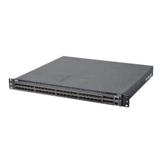
- Page 1 QuantaMesh T3048-LY2R Network Switch (Layer 2/3 Managed 10G/40G Switch) Installation Guide...
-
Page 2: Table Of Contents
Contents Chapter 1: Safety and Regulatory Information ......1 1.1 Copyright ...................2 1.2 About the Manual ..............2 1.3 Intended Application Uses ............2 1.4 Safety Information ..............2 1.4.1 Switch Safety Information ..........2 1.4.2 Installation Assembly Safety Instructions .......4 1.4.3 Site Selection ..............4 1.4.4 Equipment Handling Practices ........5 1.4.5 Power and Electrical Warnings ........5 1.4.6 Power Cord Warnings .............6... - Page 3 Contents 4.3.3 Web Management ............29 4.4 Upgrade the Firmware .............31 4.4.1 Upgrade the Firmware Image File ........31 4.4.2 Upgrade Kernel, Uboot and Rootfs .......33 Chapter 5: Troubleshooting ............35 5.1 Troubleshooting ...............36 5.1.1 Diagnostic Switch Indicator ...........36 5.1.2 Power and Cooling Problems ........36 5.1.3 Installation ..............37 5.1.4 In-Band Access ............37 5.2 Replace the Power Supply Unit ..........37...
- Page 4 List of Figures Figure 2-1: Front Panel View ............13 Figure 2-2: SFP+ and QSFP+ Port LEDs ........13 Figure 2-3: Console and Management Port LEDs......14 Figure 2-4: Rear Panel View ............15 Figure 3-1: Install Switch on Rack (Without Rail) ......18 Figure 3-2: Holes Alignment ............18 Figure 3-3: Secure Position .............18 Figure 3-4: Pull Out Rack Rail ............19 Figure 3-5: Install Switch on Rail .............19...
- Page 5 List of Tables Table 1-1: Manual Conventions Icon ..........2 Table 1-2: Product Regulatory Compliance Markings .....11 Table 2-1: SFP+ and QSFP+ Port LEDs .........13 Table 2-2: Console and Management Port LEDs ......14 Table 2-3: Power Supply and Fan Speed LEDs ......15 Table 4-1: Web Browser Utility Screen..........30 Table 5-1: Troubleshooting Tips ............36...
-
Page 6: Chapter 1: Safety And Regulatory Information
Chapter 1: Safety and Regulatory Information This chapter contains important information on safety and regulatory, as well as conventions used in this installation guide. Read this guide before installing and operating the system. -
Page 7: Copyright
All trademarks and logos mentioned in this guide are the properties of their respective holders. Copyright © 2012 Quanta Computer Inc. All rights reserved. About the Manual This installation guide is meant for network administrators with inept knowledge in network management. - Page 8 Safety and Regulatory Information Follow the safety guidelines below to ensure personal safety and protect the system and the working environment from potential damage. CAUTION: The power supplies in the system may produce high voltages and energy hazards which can cause bodily harm. Do not remove the covers and access any of the components inside the system.
-
Page 9: Installation Assembly Safety Instructions
Safety and Regulatory Information • Observe extension cable and power strip ratings. Ensure that the total ampere rating of all products plugged into the extension cable or power strip does not exceed 80% of the ampere ratings limit for the extension cable or power strip. •... -
Page 10: Equipment Handling Practices
Safety and Regulatory Information • Provided with a properly grounded wall outlet. • Provided with sufficient space to access the power supply cord(s), because they serve as the product’s main power disconnect. • Provided with either two independent AC power sources or two independent phases from a single source. 1.4.4 Equipment Handling Practices Reduce the risk of personal injury or equipment damage: •... -
Page 11: Power Cord Warnings
Safety and Regulatory Information 1.4.6 Power Cord Warnings If an AC power cord was not provided with your product, purchase one that is approved for use in your country. CAUTION: To avoid electrical shock or fire, check the power cord(s) that will be used with the product as follows: • Do not attempt to modify or use the AC power cord(s) if they are not the exact type required to fit into the grounded electrical outlets. -
Page 12: Rack Mount Warnings
Safety and Regulatory Information CAUTION: Unless you are adding or removing a hot-plug component, allow the system to cool before opening the covers. To avoid the possibility of coming into contact with hot component(s) during a hot-plug installation, be careful when removing or installing the hot-plug component(s). CAUTION: To avoid injury do not contact moving fan blades. If your system is supplied with a guard over the fan, do not operate the system without... -
Page 13: Other Hazards
Safety and Regulatory Information 1.4.9 Other Hazards 1.4.9.1 Battery Replacement CAUTION: There is the danger of explosion if the battery is incorrectly replaced. When replacing the battery, use only the battery recommended by the equipment manufacturer. CAUTION: Dispose of batteries according to local ordinances and regulations. CAUTION: Do not attempt to recharge a battery. -
Page 14: Regulatory And Compliance Information
Safety and Regulatory Information Regulatory and Compliance Information 1.5.1 Electromagnetic Compatibility Notices 1.5.1.1 FCC Verification Statement (USA) This device complies with Part 15 of the FCC Rules. Operation is subject to the following two conditions: (1) this device may not cause harmful interference, and (2) this device may accept any interference received, including interference that may cause undesired operation. This equipment has been tested and found to comply with the limits for a Class A digital device, pursuant to part 15 of the FCC Rules. - Page 15 1.5.1.6 Restriction of Hazardous Substances (RoHS) Compliance Quanta Computer Inc. has a system in place to restrict the use of banned substances in accordance ® with the European Directive 2002/95/EC. Compliance is based on declaration that materials banned in the RoHS Directive are either (1) below all applicable threshold limits or (2) an approved / pending RoHS exemption applies.
-
Page 16: Product Regulatory Compliance Markings
Safety and Regulatory Information 1.5.2 Product Regulatory Compliance Markings This product is marked with the following product certification markings: Table 1-2: Product Regulatory Compliance Markings Regulatory Region Marking Compliance cULus Listing USA / Canada Marks CE Mark Europe This device complies with Part 15 of the FCC Rules. FCC Marking Operation of this device is subject to the following two (Class A) conditions:... -
Page 17: Chapter 2: Introduction
160G bandwidth to connect with the core switch. Each uplink QSFP+ port can be independently configured as 1 x 40G or 4 x 10G so that the maximum QuantaMesh T3048-LY2R can form a total of 64-port of 10G Ethernet switch. -
Page 18: Front Panel
Introduction Front Panel The following figures show the front panel of the switch. Figure 2-1: Front Panel View Console Port SFP+ Port LEDs QSFP+ Port LEDs T3048-LY2R USB Port MGNT SFP+ Ports QSFP+ Ports Management Port 2.1.1 LED Description The following tables describe the LEDs on the front of the switch. 2.1.1.1 SFP+ and QSFP+ Port LEDs Figure 2-2:... -
Page 19: Figure 2-3: Console And Management Port Leds
Introduction 2.1.1.2 Console and Management Port LEDs Figure 2-3: Console and Management Port LEDs T3048-LY2R System Power info. MGNT Speed Link/Activity Table 2-2: Console and Management Port LEDs Description Console Port System info. • Orange : Software boots up. • : Software is ready. -
Page 20: Rear Panel
The following items are included with a standard package. When you open the box, check if all items are included and free of damage. • One QuantaMesh T3048-LY2R Layer III 10-Gigabit Managed Switch • Mounting kit: 2 mounting brackets and screws (already install on the switch) •... -
Page 21: Chapter 3: Hardware Installation
Chapter 3: Hardware Installation This chapter describes the following topics: • Unpack the Hardware • Install the Switch • Connect to Power • Check the Installation • Connect Equipment • Connect to Console Port • Connect to Management Port • Connect to USB Port... -
Page 22: Unpack The Hardware
Hardware Installation Unpack the Hardware Ensure all items are included in the package before starting the installation. NOTE: The packing box is heavy. It is recommended for two persons to carry the box and perform the installation. Place the box on a flat and stable surface and cut the straps securing the box. Remove the hardware and place it on a flat and clean surface. Remove all other items from the box. Inspect each item to make sure all items are included and free from damage (see “Select the Location”... -
Page 23: Install The Switch
Hardware Installation 3.2.1.2 Items Required for Installation The following items are required for installing, configuring, and connecting the switch: • A workstation • Ethernet cable • Console cable • SFP+ modules • QSFP+ modules • Phillips screwdriver 3.2.2 Install the Switch 3.2.2.1 Install in a Rack You can install the switch in most standard 19-inch (48.3-cm) racks. Without Rail Installation Align the built-in mounting ear to the rack holes and secure them with screws. -
Page 24: Figure 3-4: Pull Out Rack Rail
Hardware Installation Pull out the internal rail. Figure 3-4: Pull Out Rack Rail Align the brackets to the rail holes and secure them with screws. Figure 3-5: Install Switch on Rail... -
Page 25: Connect To Power
Hardware Installation Connect to Power The switch has two Power Supply Units (PSU). Each PSU has an AC power connector. Depending on your needs, you may opt to use one or both PSUs at a time. To connect the switch to a power source, do the following: Connect one end of the AC power cord to an AC power connector. -
Page 26: Qsfp+ Port
Hardware Installation To install an SFP+ module, do the following: Slide the SFP+ module into an SFP+ port. Figure 3-7: Connect SFP+ Module Push completely until the module locks into place. Repeat the above procedures to install additional SFP+ modules. The SFP+ port LED lights green when the network link is established. -
Page 27: Connect To Console Port
Hardware Installation To install a QSFP+ module, do the following: Slide the QSFP+ module into a QSFP+ port. Figure 3-9: Connect QSFP+ Module Push completely until the module locks into place. Repeat the above procedures to install additional QSFP+ modules. The QSFP+ port LED lights green when the network link is established. -
Page 28: Connect To Management Port
Hardware Installation To connect to the console, do the following: Connect the RJ-45 connector to the console port of the switch. Figure 3-10: Connect to Console Port Connect the RS-232 end to a terminal or PC. Manage the switch using the CLI commands (refer to the CLI User Manual for more information). NOTE: •... -
Page 29: Connect To Usb Port
Hardware Installation Connect the other end of the Ethernet cable to a network. The Management port LED (Link/Activity LED) lights green when the network link is established. NOTE: Ethernet cables are not included in the package. Contact your dealer to purchase. Connect to USB Port The USB port is used to connect a high-speed USB device. -
Page 30: Chapter 4: Initial Configuration
Chapter 4: Initial Configuration This chapter describes the following topics: • Initial Configuration Process • Configure the IP Address • Manage the Switch • Upgrade the Firmware... -
Page 31: Initial Configuration Process
<Enter>. The “ (Quanta) >” prompt appears. From this point, you can execute CLI commands which are limited to the general user. To view the commands, input “?”; a list of the available commands appears. -
Page 32: Obtain Ip Address By Dhcp
<gateway>” (where <gateway> is a value between 0.0.0.0 to 255.255.255.255). From this point, the IP address, subnet mask, and gateway of the switch has been set. On the command prompt, input “exit” to go back one level. The prompt changes to “(Quanta) #”. Input “ show ip interface” to display the network configurations of the switch. -
Page 33: Manage The Switch
Initial Configuration Manage the Switch After the initial configuration, you may manage and monitor network activity by CLI or SNMP management, or by using the Web browser utility. 4.3.1 CLI Management The Command Line Interface (CLI) is administered when the terminal is directly connected to the Console port of the switch. This is an out-of-band connection, which means that it is on a different circuit than normal network communications, and thus works even when the network is down. -
Page 34: Web Management
Initial Configuration 4.3.3 Web Management Use Web Browser Utility to manage and monitor the switch in a user-friendly interface. 4.3.3.1 Access the Web Browser Utility The switch has a Web Browser Utility that you can use to configure the switch. From the Web Browser Utility, the network administrator can monitor, control and manage the switch from a computer on the same local area network (LAN). -
Page 35: Figure 4-6: The Web Browser Utility Screen
Initial Configuration 4.3.3.2 The Web Browser Utility Interface Figure 4-6: The Web Browser Utility Screen Table 4-1: Web Browser Utility Screen Parts Description Menu Click a menu folder to access the submenu functions. Ports Click a port number to view and configure the port. Toggle icon Click to toggle between showing the front and rear panel of the switch. Settings Screen Displays the configurations of the selected menu, submenu or port. -
Page 36: Upgrade The Firmware
Initial Configuration SNMP v3 User Configuration, select the SNMP v3 Access Mode, Authentication Protocol, and if necessary enter the Encryption Key. Submit. The user account is modified or created. When done, click NOTE: If you want to completely remove a user account, select the user and click the Delete button on the bottom of the screen. -
Page 37: Figure 4-8: Example Of Tftp Server Screen
Initial Configuration Figure 4-8: Example of TFTP Server Screen The switch supports two images. This is to ensure that if one image file fails, another backup is ready for use. Use the “dir” command to check if the image files exist. If the switch already contains 2 images, you need to remove one of the images and use the “delete <image name>” command to delete the non-startup image. Figure 4-9: Delete Image Screen Sample Input the following command to update the image: “copy tftp://<server ip addr>/<file name>... -
Page 38: Upgrade Kernel, Uboot And Rootfs
Initial Configuration 4.4.2 Upgrade Kernel, Uboot and Rootfs After upgrading the firmware image file, check if there is a need to upgrade the kernel, uboot, and root file system. To determine whether an upgrade is necessary, perform the following: “whichboot” command to check the switch kernel and Boot to normal mode and execute the uboot versions. Figure 4-12: Check Version Screen Sample Check the firmware release notes to determine whether an upgrade is necessary. -
Page 39: Figure 4-14: Example Of Tftp Server Screen
Initial Configuration Figure 4-14: Example of TFTP Server Screen Reboot the switch. When the switch boots up, and the “ Hit any key to stop autoboot” message is displayed, press any key to stop autoboot. Figure 4-15: On the “=>” prompt, use the following commands to download uboot, kernel, and rootfs image files: “copy -b tftp://<server ip addr>/<uboot filename>”... -
Page 40: Chapter 5: Troubleshooting
Chapter 5: Troubleshooting This chapter tabulates the common problems and solutions that you may encounter when using the switch and provides customer service information. -
Page 41: Troubleshooting
Troubleshooting & Specifications Troubleshooting Below is a list of the common problems that you may encounter when using the switch. Try to solve these problems with the suggested solutions before calling for service. If problems persist, contact customer support. 5.1.1 Diagnostic Switch Indicator Table 5-1: Troubleshooting Tips... -
Page 42: Installation
Troubleshooting & Specifications 5.1.3 Installation Verify that all system components have been properly installed. If one or more components appear to be malfunctioning (such as the power cord or network cabling), test them in an alternate environment where you are sure that all the other components are functioning properly. 5.1.4 In-Band Access You can access the management agent in the switch from anywhere within the attached network... -
Page 43: Remove The Power Supply Unit
Troubleshooting & Specifications 5.2.1 Remove the Power Supply Unit Disconnect the AC power cord of the PSU that you want to remove. CAUTION: Ensure that the AC power cord is disconnected from the PSU that you want to remove. Press the plug retainer and pull by the handle to slide the PSU away from the chassis. Figure 5-2: Remove Power Supply Unit Take note of the part number of the removed PSU. -
Page 44: Replace The Hot-Swappable Fan Module
Troubleshooting & Specifications Replace the Hot-Swappable Fan Module The switch has three hot-swappable fan modules. These fan modules can be replaced without the use of special tools. 5.3.1 Remove the Fan Module Press the handle retainer and pull by the handle to slide the fan module away from the chassis. Figure 5-3: Remove Hot-swappable Fan Module Take note of the part number of the removed fan module.
Need help?
Do you have a question about the QuantaMesh T3048-LY2R and is the answer not in the manual?
Questions and answers