Table of Contents
Advertisement
Quick Links
www.altronics.com.au
Operating Manual
A 4210 80VA Hearing Induction Loop Amplifier
A 4212 280VA Hearing Induction Loop Amplifier
SUITABLE FOR SIMPLE ONE AMPLIFIER DESIGNS.
NOT DESIGNED FOR COMPLEX MULTIPLE AMPLIFIER SYSTEMS.
NOT SUITABLE FOR INSTALLS WITH ADJACENT SYSTEMS.
Redback® Proudly Made In Australia
Distributed by Altronic Distributors Pty. Ltd.
Phone: 1300 780 999 Fax: 1300 790 999 Internet: www.altronics.com.au
IMPORTANT NOTE:
Please read these instructions carefully from front to back prior to installation.
They include important setup instructions.
Failure to follow these instructions may prevent the amplifier from working as designed.
User manual revision number: 1.0 26/05/2015
Advertisement
Table of Contents

Subscribe to Our Youtube Channel
Related Manuals for Redback A 4210


Summary of Contents for Redback A 4210
-
Page 1: Important Note
Operating Manual A 4210 80VA Hearing Induction Loop Amplifier A 4212 280VA Hearing Induction Loop Amplifier SUITABLE FOR SIMPLE ONE AMPLIFIER DESIGNS. NOT DESIGNED FOR COMPLEX MULTIPLE AMPLIFIER SYSTEMS. NOT SUITABLE FOR INSTALLS WITH ADJACENT SYSTEMS. Redback® Proudly Made In Australia Distributed by Altronic Distributors Pty. - Page 2 Australian Made Status All Redback house products made by Altronics will now be sporting the official Australian Made logo. Since starting manufacturing of commercial audio equipment in the mid 70’s we have always taken pride in producing a quality local product.
-
Page 3: Table Of Contents
3.1 Loop Design Guidelines 3.2 The Loop 3.3 Loop Types 3.4 The Amplifier 3.5 Theoretical Loops 3.6 Practical Loops 3.7 Steps In Loop Design 3.8 Placement of Loops 4.0 Terms and Abbreviations 5.0 Specifications www.altronics.com.au Redback® Proudly Made In Australia... -
Page 4: Overview
2 ohms and are short circuit proof. Great for places of worship, community halls, museums public places, etc. The A 4210 80VA model delivers 3.5A RMS, 5 Amps peak and the A 4212 280VA model delivers 8A RMS, 11 Amps peak into a typical Loop Resistance of 0.2Ω to 1.7Ω (max 2Ω). -
Page 5: Front Panel Guide
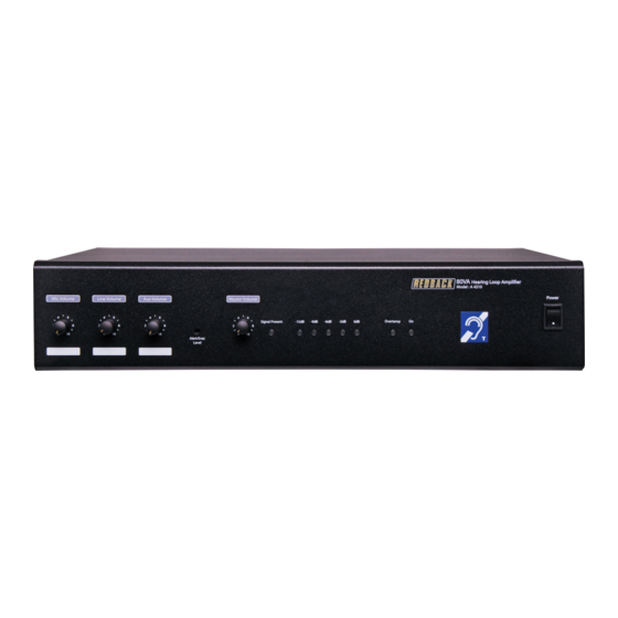
Overview 1.4 FRONT PANEL GUIDE Fig 1.4 shows the layout of the front panel. 80VA Hearing Loop Ampli er Model : A 4210 Power Mic Vol Line Vol Aux Vol Master Signal Present -15dB -9dB -6dB -3dB Overtemp Alert/Evac Level Fig 1.4... -
Page 6: Rear Panel Connections
The AUX inputs are dual RCA connectors which are internally mixed to produce a mono input signal. EWIS Input The EWIS inputs are dual RCA connectors which are internally mixed to produce a mono input signal. Redback® Proudly Made In Australia www.altronics.com.au... -
Page 7: Setup
2.1 SETUP GUIDE The A 4210 and A 4212 amplifiers have a total of four inputs. A balanced 3 Pin female XLR (Mic input), a balanced 3 Pin female XLR (Line input), a dual RCA (Aux input) and a dual RCA (EWIS input). -
Page 8: Ewis Input
Figure 2.1 demonstrates how to connect the A 4575A controller to the A 4210/12 amplifier. The output of the A 4575A Evacuation controller is connected to the EWIS Input of the A 4210 using dual RCA leads. The output level of the signal from the Evacuation controller is set by the EWIS volume adjustment on the front of the A 4210/12 amplifier. -
Page 9: Dip Switch Settings
Signal Presence Indicates when a signal is present at any of the Mic, Line, Aux or EWIS inputs. VU Meter The dB output of the amplifier is indicated by the 0dB to -15dB LED’s. www.altronics.com.au Redback® Proudly Made In Australia... -
Page 10: Loop Design
The A 4210/12 amplifiers are not intended for use in multiple amplifier designs. As for the loop resistance, Altronics A4210 and A4212 Hearing Loop Amplifiers preferred load resistance range is 0.2Ω to 1.7Ω... -
Page 11: The Amplifier
Frequency Response of the system shall be from 100Hz to 5000Hz. The variation should be no more than +/- 3dB from the value taken at 1kHz. The international standard is IEC 60118.4 (also known as SN, EN or BS 60118.4) www.altronics.com.au Redback® Proudly Made In Australia 11... -
Page 12: Theoretical Loops
Refer to the cross section of loop below and notice that at the centre the FS is lower than just inside the edge of loop wire on each side of perimeter. Redback® Proudly Made In Australia www.altronics.com.au... -
Page 13: Practical Loops
Verify signal quality with FS at 400mA/m (approximate) Note: correct signal should be a pulsed tone For reference and repeatable calibrations, manually plot long term FS readings in selected reference locations. Fit appropriate signage for system compliance under BCA. www.altronics.com.au Redback® Proudly Made In Australia 13... -
Page 14: Placement Of Loops
If electric guitars are used, they should be checked during the pre-installation loop test in order to determine if their magnetic pickups are sensitive to the planned loop location. Use of Dynamic Mics to be confined outside of Loop area. Fig 4.0 illustrates the typical frequency repsonse required. Fig 4.0 Redback® Proudly Made In Australia www.altronics.com.au... -
Page 15: Terms And Abbreviations
2:1 for dynamics control (fast attack) Input: 3 pin XLR, Stereo RCA Output: Loop connection via pluggable terminals Power: 240V ac Dimensions: 432W x 380D x 88H *Specifications subject to change without notice www.altronics.com.au Redback® Proudly Made In Australia 15... - Page 16 Warranty All Australian made Redback products are covered by a 10 year warranty. Should a product become faulty please contact us to obtain a return authorisation number. Please ensure you have all the relevant documentation on hand. We do not accept unauthorised returns. Proof of purchase is required so please retain your invoice.
Need help?
Do you have a question about the A 4210 and is the answer not in the manual?
Questions and answers