Table of Contents
Advertisement
Advertisement
Table of Contents

Related Manuals for VC VC40 series

Summary of Contents for VC VC40 series
- Page 1 ® ® Vision Components The Smart Camera People VC4XXX Operating Manual Hardware Specifications and special Software Functions of VC40XX and VC44XX Smart Cameras Revision 3.3 – 23 Jul 2014 Document name: VC4XXX_HW.pdf Vision Components GmbH Ettlingen, Germany...
- Page 2 VC20XX cameras can be used for this camera. Further References under “Support + Download” on www.vision-components.com: „Support News“ – for up to date information on VC Software and Documentation. „Knowledge Base / FAQ“ - searchable Database with latest software developments, frequently asked questions and demo programs.
-
Page 3: Table Of Contents
Pin assignments Power Supply and IO Interface 6.3.2 Electrical specifications Camera Power Supply Camera 6.3.3 Shutdown Function for VC Professional and VC Optimum 6.3.4 Electrical Specifications digital PLC IO Interface 6.3.5 Available Accessories / Cables for Power Supply and IO Interface Video Output Interface 6.4.1... - Page 4 Appendix B: Block diagram VC4018/ -16 Smart Cameras Appendix C: Dimensions VC Base (VC4018 and VC4016) Appendix D: Dimensions VC Professional and VC Optimum models Appendix E: Drawing Camera Head VC40XX and VC44XX Appendix F: Spectral Transmission of IR Filter...
-
Page 5: General Information
Together with the almost complete software compatibility this will aide the upgrade of existing applications. For the new “VC Base Family range” it was possible to shorten the camera housing even further, offering a complete vision system with a very small form factor. -
Page 6: Feature Overview Smart Camera Families
The high speed trigger input of all VC4XXX family allows jitter free taking – even when inspecting fast moving objects. As the previous generation the VC4XXX also includes 24 V digital IO’s and the VC Professional and VC Optimum cameras incorporate a direct video output. - Page 7 Real time clock Temperature sensor Trigger Event Programmable Input Lookup Table Refer to the Appendix A and B for hardware structure diagrams of VC Base, VC Professional and VC Optimum Family Smart Cameras. 1996-2014 Vision Components GmbH Ettlingen, Germany...
-
Page 8: Technical Specifications "Vc Base
VC4XXX_HW.pdf – Hardware Documentation VC4XXX Smart Cameras 3 Technical Specifications “VC Base” 3.1 Technical Specifications VC4018 Component / Feature Specification CCD Sensor: 1/3" SONY ICX424AL - also available with color sensor (Bayer Filter) Active pixels: 640(H) x 480(V) Pixel size: 7.4(H) x 7.4(V) µm... -
Page 9: Technical Specifications Vc4016
VC4XXX_HW.pdf – Hardware Documentation VC4XXX Smart Cameras 3.2 Technical Specifications VC4016 Component / Feature Specification CCD Sensor: 1/3" SONY ICX204 AL - also available with color sensor (Bayer Filter) Active pixels: 1024 (H) x 768 (V) Pixel size: 4.65 (H) x 4.65 (H) µm Active sensor size: 4.76(H) x 3.57(V) mm High-speed shutter:... -
Page 10: Technical Specifications "Vc Professional
VC4XXX_HW.pdf – Hardware Documentation VC4XXX Smart Cameras 4 Technical Specifications “VC Professional” 4.1 Technical Specifications VC4038 Component / Feature Specification CCD Sensor: 1/3 “ SONY ICX424AL Active pixels: 640(H) x 480(V) Pixel size: 7.4 µm (H) x 7.4 µm (V) Active sensor size: 4.74(H) x 3.55(V) mm... -
Page 11: Technical Specifications Vc4058
VC4XXX_HW.pdf – Hardware Documentation VC4XXX Smart Cameras 4.2 Technical Specifications VC4058 Component / Feature Specification CCD Sensor: 1/3”Kodak KAI-0340 Active pixels: 640(H) x 480(V) Pixel size: 7.4 µm (H) x 7.4 µm (V) Active sensor size: 4.74(H) x 3.55(V) mm Integration: full-frame progressive scan Picture taking:... - Page 12 VC4XXX_HW.pdf – Hardware Documentation VC4XXX Smart Cameras 4.3 Technical Specifications VC4065 Component / Feature Specification CCD Sensor: 1/2" SONY ICX415AL Active pixels: 768(H) x 582(V) Pixel size: 8.3(H) x 8.3(V) µm Active sensor size: 6.37(H) x 4.83(V) mm Integration: full-frame progressive scan Picture taking: program-controlled or triggered externally;...
-
Page 13: Technical Specifications Vc4066
VC4XXX_HW.pdf – Hardware Documentation VC4XXX Smart Cameras 4.4 Technical Specifications VC4066 Component / Feature Specification CCD Sensor: 1/3" SONY ICX204AL Active pixels: 1024(H) x 768(V) Pixel size: 4.65(H) x 4.65(V) µm Active sensor size: 4.76(H) x 3.57(V) mm Integration: full-frame progressive scan Picture taking: program-controlled or triggered externally;... -
Page 14: Technical Specifications Vc4067 & Vc4067Nir
VC4XXX_HW.pdf – Hardware Documentation VC4XXX Smart Cameras 4.5 Technical Specifications VC4067 & VC4067NIR Component / Feature Specification CCD Sensor: 2/3" SONY ICX285AL EXview HAD CCD Active pixels: 1280(H) x 1024 (V) 6.45(H) x 6.45(V) µm Pixel size: 8.26(H) x 6.60(V) mm Active sensor size: Integration: full-frame progressive scan... -
Page 15: Technical Specifications Vc4068
VC4XXX_HW.pdf – Hardware Documentation VC4XXX Smart Cameras 4.6 Technical Specifications VC4068 Component / Feature Specification CCD Sensor: 1/2" SONY ICX205A Active pixels: 1280(H) x 1024 (V) 4.65(H) x 4.65(V) µm Pixel size: 5.95(H) x 4.76(V) mm Active sensor size: Integration: full-frame progressive scan Picture taking: program-controlled or triggered externally;... -
Page 16: Technical Specifications "Vc Optimum
VC4XXX_HW.pdf – Hardware Documentation VC4XXX Smart Cameras 5 Technical Specifications “VC Optimum” 5.1 Technical Specifications VC4438 Component / Feature Specification CCD Sensor: 1/3 “ SONY ICX424AL Active pixels: 640(H) x 480(V) Pixel size: 7.4 µm (H) x 7.4 µm (V) Active sensor size: 4.74(H) x 3.55(V) mm... -
Page 17: Technical Specifications Vc4458
VC4XXX_HW.pdf – Hardware Documentation VC4XXX Smart Cameras 5.2 Technical Specifications VC4458 Component / Feature Specification CCD Sensor: 1/3”Kodak KAI-0340 Active pixels: 640(H) x 480(V) Pixel size: 7.4 µm (H) x 7.4 µm (V) Active sensor size: 4.74(H) x 3.55(V) mm Integration: full-frame Picture taking:... -
Page 18: Technical Specifications Vc4459
VC4XXX_HW.pdf – Hardware Documentation VC4XXX Smart Cameras 5.3 Technical Specifications VC4459 Component / Feature Specification CMOS Sensor: 1/3" CMOSIS CMV300 Active pixels: 640(H) x 480(V) Pixel size: 7.4(H) x 7.4 (V) µm Active sensor size: 4.74(H) x 3.55(V) mm High-speed shutter: 8 µs + steps of 2 µs Low-speed shutter: up to 600 ms adjustable integration time... -
Page 19: Technical Specifications Vc4465
VC4XXX_HW.pdf – Hardware Documentation VC4XXX Smart Cameras 5.4 Technical Specifications VC4465 Component / Feature Specification CCD Sensor: 1/2" SONY ICX415AL Active pixels: 768(H) x 582(V) Pixel size: 8.3(H) x 8.3(V) µm Active sensor size: 6.37(H) x 4.83(V) mm Integration: full-frame progressive scan Picture taking: program-controlled or triggered externally;... -
Page 20: Technical Specifications Vc4465C
VC4XXX_HW.pdf – Hardware Documentation VC4XXX Smart Cameras 5.5 Technical Specifications VC4465C Component / Feature Specification CCD Sensor: 1/2” SONY ICX415AQ Active pixels: 768(H) x 582(V) Pixel size: 8.3(H) x 8.3(V) µm Active sensor size: 6.37(H) x 4.83(V) mm Integration: full-frame progressive scan Picture taking: program-controlled or triggered externally;... -
Page 21: Technical Specifications Vc4466
VC4XXX_HW.pdf – Hardware Documentation VC4XXX Smart Cameras 5.6 Technical Specifications VC4466 Component / Feature Specification CCD Sensor: 1/3" SONY ICX204AL Active pixels: 1024(H) x 768(V) Pixel size: 4.65(H) x 4.65(V) µm Active sensor size: 4.76(H) x 3.57(V) mm Integration: full-frame progressive scan Picture taking: program-controlled or triggered externally;... -
Page 22: Technical Specifications Vc4467 & Vc4467Nir
VC4XXX_HW.pdf – Hardware Documentation VC4XXX Smart Cameras 5.7 Technical specifications VC4467 & VC4467NIR Component / Feature Specification CCD Sensor: 2/3" SONY ICX285AL EXview HAD CCD Active pixels: 1280(H) x 1024 (V) 6.45(H) x 6.45(V) µm Pixel size: 8.26(H) x 6.60(V) mm Active sensor size: Integration: full-frame progressive scan... -
Page 23: Technical Specifications Vc4468
VC4XXX_HW.pdf – Hardware Documentation VC4XXX Smart Cameras 5.8 Technical Specifications VC4468 Component / Feature Specification CCD Sensor: 1/2" SONY ICX205A Active pixels: 1280(H) x 1024 (V) 4.65(H) x 4.65(V) µm Pixel size: 5.95(H) x 4.76(V) mm Active sensor size: Integration: full-frame progressive scan Picture taking: program-controlled or triggered externally;... -
Page 24: Technical Specifications Vc4472
VC4XXX_HW.pdf – Hardware Documentation VC4XXX Smart Cameras 5.9 Technical Specifications VC4472 Component / Feature Specification CCD Sensor: 1/1.8” (8,923mm) SONY ICX274AL Active pixels: 1600(H) x 1200 (V) 4.4µm (H) x 4.4µm (V) Pixel size: 7.04mm (H) x 5.28mm (V) Active sensor size: Integration: full-frame progressive scan Picture taking:... -
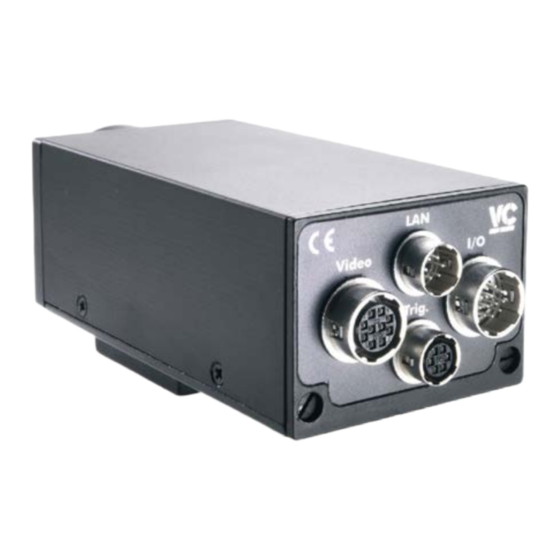
Page 25: Vc4Xxx Camera Interfaces
VC4XXX_HW.pdf – Hardware Documentation VC4XXX Smart Cameras 6 VC4XXX Camera Interfaces LAN / Ethernet Interface PLC IO- / Power Supply Interface Video OUT Interface Trigger- / Serial RS232-/ Keypad- Interface The VC40XX Smart Camera incorporates the following connector interfaces: 1. LAN / Ethernet Interface 2. -
Page 26: Lan / Ethernet Interface
VC4XXX_HW.pdf – Hardware Documentation VC4XXX Smart Cameras 6.1 LAN / Ethernet Interface 6.1.1 Pin Assignments LAN / Ethernet Interface Signal rear view camera socket: 6.1.2 Available Accessories for LAN / Ethernet socket Signal Pin (to cam.) Pin (to PC) Cable Color Cable Color 20m patch cable 10m patch cable... -
Page 27: Trigger-/ V24- (Rs232)-/ Keypad- / Encoder Interface
VCRT 5.24-8 VC4468 VCRT 5.24-13 “VC Base Family” cameras VC4016 and VC4018 do not include an Encoder Interface. VC4058, VC4438, VC4458, VC4465 and VC4472 all feature an Encoder Interface from the start. Multiple use of the trigger interface: A “Y” adaptor cable is available for connecting several components to the trigger interface – refer to section 6.2.4 for details. -
Page 28: Pin Assignments Trigger-/ V24 (Rs232)-/ Keypad/ - Encoder Interface
VC4XXX_HW.pdf – Hardware Documentation VC4XXX Smart Cameras 6.2.1 Pin Assignments Trigger-/ V24 (RS232)-/ Keypad/ - Encoder Interface Signals RS232 / Signals Encoder Interface rear view camera socket: Trigger Standard Trigger V24 TxD Out 0+ (Zero Pulse Encoder) + 5V Out + 5V Out (Power Supply TTL Encoder) GND (Power Supply TTL Encoder) -
Page 29: V24 (Rs232) Serial Cable
VC4XXX_HW.pdf – Hardware Documentation VC4XXX Smart Cameras 6.2.3 V24 (RS232) serial Cable Signal Cable Color Length: 5m V24 TxD Out brown + 5V Out pink grey V24 RxD In white HIROSE 10A-7P-6SC Cable: 0.14mm LiYCY 6 conductors 6-pin. solder plug shielded, outside diameter 5 mm Trigger Out Trigger In... -
Page 30: Electrical Specifications Of Trigger- / Serial-/ Keypad / Encoder Interface
Siemens 1XP8001-2, TTL, Ub = 5-10V, for 3 phase 220V asynchrone motor, size H58 Din 332 The VC Base Family camera range VC4018 and -16 incorporate opto coupler on trigger in and out. 1996-2014 Vision Components GmbH Ettlingen, Germany... - Page 31 VC4XXX_HW.pdf – Hardware Documentation VC4XXX Smart Cameras Suggested Trigger Input Circuit PNP Trigger Input Circuit Camera Circuit 5V Out, Pin 2 TTL Input Trig In, Pin 6 1kΩ GND, Pin 3 The 1kΩ internal pull down resistor is not included in the initial hardware release (delivery until end of 2005).
- Page 32 VC4XXX_HW.pdf – Hardware Documentation VC4XXX Smart Cameras Trigger Input Circuit compatible to VC20XX and VC40XX cameras: Trigger Input Circuit Camera Circuit 5V Out, Pin 2 (VC20XX and VC40XX) Trig In+, Pin 6 (VC20XX and VC40XX) GND, Pin 3 (VC20XX and VC40XX) Trig In - Pin 1 (VC20XX only!) The trigger input circuit shown above can be used to connect both –...
-
Page 33: Power Supply And Io Interface
6.3.2 Electrical specifications Camera Power Supply Camera The power supply of the VC Base Family range differs form the VC Professional and VC Optimum Smart Camera ranges. With the Professional and Optimum cameras it is possible to supply the PLC outputs with a voltage different from the camera power supply via pin 1 and 9. -
Page 34: Shutdown Function For Vc Professional And Vc Optimum
6.3.3 Shutdown Function for VC Professional and VC Optimum The VC Professional and VC Optimum Smart Cameras incorporate a circuit to detect and protocol power failures. If the PLC output power supply (12-24V PLC, Pin 1 and 9) of the VC4038 to VC4472 cameras is interrupted, the system variable “POWFAIL”... -
Page 35: Electrical Specifications Digital Plc Io Interface
Please observe the current and voltage ratings specified in the following sections. The PLC circuit of all VC Professional and Optimum Smart Cameras is separated from the camera power supply. This however is not the case with the VC Base Family range models VC4016 and VC4018. -
Page 36: Available Accessories / Cables For Power Supply And Io Interface
VC4XXX_HW.pdf – Hardware Documentation VC4XXX Smart Cameras 6.3.4.1 Connection of Inputs VC Professional and VC Optimum Family external switch, 4 digital Inputs relais, PLC, light Operating Voltage 12 to 24 V barrier, etc. Threshold Voltage 8V (input high for signals... -
Page 37: Video Output Interface
Please order "with 2nd connector", if you need a DSUB15 connector at the other end. Refer to section 7.2 for a list of available cables with order numbers. The video interface is not available for the VC Base Family cameras VC4016 and VC4018. 1996-2014 Vision Components GmbH Ettlingen, Germany... -
Page 38: Order Numbers Cameras And Accessories
VC4XXX_HW.pdf – Hardware Documentation VC4XXX Smart Cameras Order Numbers Cameras and Accessories 7.1 Order numbers of all available VC4XXX Camera Models: 7.1.1 Order Numbers “VC Base” Models: Article Description Order Number VC4018 VK000258 VC4018C VK000267 VC4016 VK000257 VC4016C VK000268 7.1.2 Order Numbers “VC Professional”... -
Page 39: Order Numbers Of All Available Vc4Xxx Accessories
7.2 Order numbers of all available VC4XXX Accessories For interface cables and connectors available also consult the corresponding section in chapter 6 of this manual as well as the “VC Smart Camera Accessories” section – under the “Product” section on our website www.visoin-comp.com... - Page 40 VC4XXX_HW.pdf – Hardware Documentation VC4XXX Smart Cameras V24 (RS232) Serial Cable (Refer to section 6.2.3): These cables differ from the serial VC20XX C6 cables! Article Description Order Number Camera Connector Second Connector HRS male 6 pin without connector 5m V24 cable VK000243 D-SUB 9 pin female HRS male 6 pin...
- Page 41 VC4XXX_HW.pdf – Hardware Documentation VC4XXX Smart Cameras VGA Video Output Cable (refer to section 6.4.2): Article Description Order Number Camera Connector Second Connector HRS connector male 10 pin without connector 5m SVGA-cable VK000006 HRS connector male 10 pin HD-SUB 15 pin male 5m SVGA-cable with VK000083 DSUB...
- Page 42 EK000629 The feasibility of remote head mounting depends on working conditions (electrical noise, electro magnetic radiation emitted from the camera, voltage drop over sensor cable, etc.). VC’s CE certification is valid only for the standard camera set up. 1996-2014 Vision Components GmbH Ettlingen, Germany...
-
Page 43: Programming Vc4Xxx Smart Cameras
Documentation Functions Please also check the “Getting Started VC” (Schnellstart VC Smart Kameras) as well as the “Support News” and the “Knowledge Base / FAQ” on our website (see the “References” section on the very first Page of this manual). -
Page 44: Programming The Encoder Interface
VC4XXX_HW.pdf – Hardware Documentation VC4XXX Smart Cameras if(c!=0x1b) io_fputc(c, tty); fclose(tty); /* close serial device */ fclose(tty); /* close RS485 8.2 Programming the Encoder Interface Refer to section 6.2 for details on this interface and also the separate “Encoder Application Notes” under “References”... -
Page 45: Appendix A: Block Diagram Vc40Xx Smart Cameras
VC4XXX_HW.pdf – Hardware Documentation VC4XXX Smart Cameras Appendix A: Block diagram VC40XX Smart Cameras Appendix B: Block diagram VC4018/ -16 Smart Cameras 4 MB Flash Eprom C64XX 32 MB SDRAM Bus Controller Trigger In/ Out Trigger In/ CCD - A/D Con- FIFO Sensor verter... -
Page 46: Appendix C: Dimensions Vc Base (Vc4018 And Vc4016)
VC4XXX_HW.pdf – Hardware Documentation VC4XXX Smart Cameras Appendix C: Dimensions VC Base (VC4018 and VC4016) Maximal torque for M6 screws (all camera models) : 10 Nm Appendix D: Dimensions VC Professional and VC Optimum models 1996-2014 Vision Components GmbH Ettlingen, Germany... -
Page 47: Appendix E: Drawing Camera Head Vc40Xx And Vc44Xx
VC4XXX_HW.pdf – Hardware Documentation VC4XXX Smart Cameras Appendix E: Drawing Camera Head VC40XX and VC44XX 1996-2014 Vision Components GmbH Ettlingen, Germany... -
Page 48: Appendix F: Spectral Transmission Of Ir Filter
VC4XXX_HW.pdf – Hardware Documentation VC4XXX Smart Cameras Appendix F: Spectral Transmission of IR Filter Note: This IR cut filter is incorporated in every VC40XX camera. The IR filter can be removed if required without loosing Vision Component’s manufacturer’s warranty. In this case, special care must be taken not to damage the CCD sensor. - Page 49 VC Optimum VC Line Visicube VC Board Cameras VC Customized Accessories VC Smart Camera Software VC Software Development Kit Ti: VCRT Operating System VCLIB Image Processing Library VC Special Libraries: Color Lib Extension Lib VCOCR Text Recognition Library VC Smart Reader...
Need help?
Do you have a question about the VC40 series and is the answer not in the manual?
Questions and answers