
Related Manuals for Agilent Technologies E5071C ENA


Summary of Contents for Agilent Technologies E5071C ENA
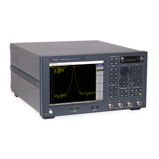
- Page 1 ® Advanced Test Equipment Rentals www.atecorp.com 800-404-ATEC (2832) Agilent E5071C ENA Network Analyzers Service Guide Eighth Edition Manufacturing No. E5071-90140 April 2012...
- Page 2 This document contains proprietary information that is protected by copyright. All rights are reserved. No part of this document may be photocopied, reproduced, or translated into another language without the prior written consent of the Agilent Technologies. Microsoft®,MS-DOS®,Windows®,Visual C++®,Visual Basic®,VBA® and Excel® are registered trademarks of Microsoft Corporation.
- Page 3 WARNINGS elsewhere in this manual may impair the protection provided by the equipment. In addition it violates safety standards of design, manufacture, and intended use of the instrument. Agilent Technologies assumes no liability for the customer’s failure to comply with these requirements. NOTE The E5071C complies with INSTALLATION CATEGORY II as well as POLLUTION DEGREE 2 in IEC61010-1.
- Page 4 To avoid the danger of introducing additional hazards, do not install substitute parts or perform unauthorized modifications to the instrument. Return the instrument to an Agilent Technologies Sales and Service Office for service and repair to ensure that safety features are maintained in operational condition.
- Page 5 Certification Agilent Technologies certifies that this product met its published specifications at the time of shipment from the factory. Agilent Technologies further certifies that its calibration measurements are traceable to the United States National Institute of Standards and Technology, to the extent allowed by the Institution’s calibration facility, or to the calibration facilities of other International Standards Organization members.
- Page 6 Typeface Conventions Sample (bold) Boldface type is used when a term is defined or emphasised. Sample (Italic) Italic type is used for emphasis. Indicates a hardkey (key on the front panel or key / [Sample] key external keyboard) labeled “Sample.” “key” may be omitted.
-
Page 7: Table Of Contents
Contents 1. General Information Precautions ................18 Software Installed . - Page 8 Contents Description ............... . 48 Test Equipment .
- Page 9 Contents Recommended adjustment for performance test failure ........86 Performance test failure troubleshooting .
- Page 10 Contents Inverter Assembly..............155 Standby Switch Assembly .
- Page 11 Contents Tools Required ..............187 Removal Procedure .
- Page 12 Contents Imix, Attenuator and Distributor Module Replacement (IMX, ATT and A4) ..... . 219 1) 2-Ports Options ..............219 2) 4-Ports Options .
- Page 13 Contents A. Manual Changes Manual Changes ..............254 B.
- Page 14 Contents R ................306 S .
- Page 15 Contents...
- Page 16 Contents...
-
Page 17: General Information
General Information The Service Manual is a guide to servicing the E5071C ENA Series Network Analyzer. The manual contains information requisite to do performance tests, adjustments, troubleshooting, and repairs. -
Page 18: Precautions
Do not allow any computer virus to infect the system. This machine has no virus check function nor anti-virus software installed. Agilent Technologies will not be held liable for any failure or damage arising from negligence regarding these prohibitions and warnings. -
Page 19: Organization Of Service Manual
Chapter 1 , “General Information,” The Service Manual is a guide to servicing the E5071C ENA Series Network Analyzer. The manual contains information requisite to do performance tests, adjustments, troubleshooting, and repairs. - Page 20 General Information Organization of Service Manual This appendix describes how to update the E5071C firmware. When you want to update the E5071C firmware, refer to this appendix. Appendix D , “Power Requirement,” Appendix E, “Messages,” The E5071C can display error messages as well as messages that indicate the internal operating status of the equipment.
-
Page 21: Instrument Covered By This Manual
The supplement for this manual is identified by this manual's printing data and is available from Agilent Technologies. If the serial prefix or number of an instrument is lower than that on the title page of this manual, see Appendix A, Manual Changes. For information concerning, a serial number prefix that is not listed on the title page or in the Manual change supplement, contact the nearest Agilent Technologies office. -
Page 22: Analyzer Options Available
General Information Analyzer Options Available Analyzer Options Available Table 1-1 lists the applicable model and options for E5071C Table 1-1 Applicable Model and Options Opt# Status Description Available Up to Over 8.5 2 Port 4 Port 8.5 GHz Option Option Option Option Active... - Page 23 General Information Analyzer Options Available Table 1-1 Applicable Model and Options Opt# Status Description Available Up to Over 8.5 2 Port 4 Port 8.5 GHz Option Option Option Option Active 4-port Test Set, 9 kHz to 8.5 7.01 or later Active 4-port Test Set, 100 kHz to 7.01 or later...
-
Page 24: Required Equipment
General Information Required Equipment Required Equipment 1) Up to 8.5 GHz Options Table 1-2 lists the recommended equipment for performing maintenance on the E5071C. Table 1-2 Recommended Test Equipment Equipment Critical specifications Recommended Model Qty. Frequency Counter Frequency: 50 MHz to 8.5 GHz Agilent 53181A with Opt.010 &... - Page 25 General Information Required Equipment Table 1-2 Recommended Test Equipment Equipment Critical specifications Recommended Model Qty. Cable BNC(m)-BNC(m) Cable, 61 cm Agilent p/n 8120-1839 Coaxial cable with Type-N (m) Agilent N6314A (p/n P,A,T connectors, 61 cm (24 in), 2 ea. 8120-8862) Cable 20 inch 50 ohm cable Agilent p/n 8121-1834...
- Page 26 General Information Required Equipment 2) Over 8.5 GHz Options Table 1-4 lists the recommended equipment for performing maintenance on the E5071C. Table 1-4 Recommended Test Equipment Equipment Critical specifications Recommended Model Qty. Frequency Counter 1 Frequency: 50 MHz to 8.5 GHz Agilent 53181A with Opt.010 &...
- Page 27 General Information Required Equipment Table 1-4 Recommended Test Equipment Equipment Critical specifications Recommended Model Qty. Cable 20 inch 50 ohm cable Agilent p/n 8121-1834 Adapter N(m)-BNC(f) Adapter Agilent p/n 1250-0780 Adapter APC 3.5 (f)-(f) Adapter Agilent p/n 85027-60005 Adapter APC 2.5 (m)-N(f) Adapter Agilent p/n 1250-1811 Torque Wrench Size: 3/4 inch...
-
Page 28: Power Meter Accuracy Test
General Information Power Meter Accuracy Test Power Meter Accuracy Test This test is intended for power meters used in testing the E5071C. The “Dynamic Accuracy Test” requires the use of a power meter that has been calibrated to a higher accuracy than the standard power meter. - Page 29 General Information Power Meter Accuracy Test NOTE It is recommended that a copy of the test record on page 32 be made, and the values be recorded on the copy, thus preserving the original for future use. Test Procedure NOTE This procedure assumes the use of the recommended equipment model numbers.
- Page 30 General Information Power Meter Accuracy Test • POLARITY: NORMAL • RANGE: 1 mW • FUNCTION: CALIBRATE Step 6. Allow the equipment to warm up for approximately 30 minutes. Do not change any connections or control setting during this time. Step 7. Zero and calibrate the power meter channel to which the range calibrator is connected: a.
- Page 31 General Information Power Meter Accuracy Test Step 17. Record the DVM voltage reading as value D in the test record. Step 18. Wait for the power meter reading to settle (no settling drift within 20 seconds). Step 19. Record the power meter reading as value E in the test record. Step 20.
-
Page 32: Test Record For Power Meter Accuracy Test
General Information Power Meter Accuracy Test Test Record for Power Meter Accuracy Test Power Meter Tested Model Number: Test Date: Serial Number: Tested by: Test Equipment Used Range Calibrator: Model No.: Serial No.: Digital Voltmeter: Model No.: Serial No.: Test Results Range Channel A Channel B... -
Page 33: Agilent Support, Services And Assistance
Agilent for repair. If you wish to send your network analyzer to Agilent Technologies for service or repair: • Include a complete description of the service requested or of the failure and a description of any failed test and any error message. - Page 34 General Information Agilent Support, Services and Assistance • Contact Agilent for instructions on where to ship your analyzer. Chapter 1...
-
Page 35: Performance Test
Performance Test This chapter provides information on how to verify the E5071C performance. -
Page 36: Introduction
Performance Test Introduction Introduction This literature provides the performance test procedures for the Agilent E5071C RF Network Analyzers. The performance test names are listed in Table 2-1. The test procedures are described sequentially in the following pages. The test name indicates the tested performance and to which performance group the tested performance belongs. -
Page 37: Test Equipment Required
Performance Test Introduction Test Equipment Required The required equipment for the performance test is listed on Table 1-2, Table 1-3, Table 1-4 and Table 1-5. Use only calibrated equipment when doing the performance test. Softkey Selection Procedure for Performance Test NOTE The procedure of the softkey selection depends on the firmware revision. -
Page 38: Aux Input Test
Performance Test 1. AUX INPUT TEST 1. AUX INPUT TEST Description This test checks the measurement accuracy of AUX Input. This test is checked, compared with the measured value of Multimeter by inputting the DC voltage to AUX-1 and 2 ports from function generator. -
Page 39: Frequency Accuracy Test
Performance Test 2. FREQUENCY ACCURACY TEST 2. FREQUENCY ACCURACY TEST Description This test checks the frequency accuracy of the E5071C test port output signal. The frequency accuracy is checked at several frequency from 9kHz to 20 GHz range. Since the E5071C employs a PLL frequency synthesizer for the signal source, the frequency accuracy at these frequency points can verify the accuarcy for the entire frequency range. -
Page 40: Rf Output Level Accuracy And Flatness Test
Performance Test 3. RF OUTPUT LEVEL ACCURACY AND FLATNESS TEST 3. RF OUTPUT LEVEL ACCURACY AND FLATNESS TEST Description This test checks the level accuracy and frequency flatness of the E5071C test port output signal. The level accuracy is checked for an output power level setting of 0 dBm for up to 8.5 GHz options and -5 dBm for over 8.5 GHz options at 50 MHz using a power meter. -
Page 41: Rf Output Level Linearity Test
Performance Test 4. RF OUTPUT LEVEL LINEARITY TEST 4. RF OUTPUT LEVEL LINEARITY TEST Description This test checks the level accuracy of the E5071C test port output signal across the specified level range. The RF output level is measured for power level settings of -20 dBm to 10 dBm in 2.5dB step increments at 9 kHz, 100 kHz, 50 MHz, 3 GHz, 4.5 GHz, 5 GHz, and -20 dBm to 9 dBm in 2.5 dB step increments at 6 GHz, and -20 dBm to 8 dBm in 2.5 dB step increments at 7 GHz, and -20 dBm to 7 dBm in 2.5 dB step increments at 8.5 GHz. -
Page 42: Trace Noise Test
Performance Test 5. TRACE NOISE TEST 5. TRACE NOISE TEST Description This test checks the trace noise level for each test port of E5071C. The trace noise level is quantified by performing a “through” measurement 32 times from 9 kHz to 8.5 GHz range (for up to 8.5 GHz options) or from 300 kHz to 20 GHz range (for over 8.5 GHz options), with a cable connected between two ports. -
Page 43: Crosstalk Test
Performance Test 6. CROSSTALK TEST 6. CROSSTALK TEST Description This test checks the crosstalks between test ports of the E5071C. The crosstalk is tested by performing "through" measurements with two test ports connected together and, short-ended "isolation" measurements with the test ports terminated with N-type "Short" devices. -
Page 44: System Dynamic Range Test
Performance Test 7. SYSTEM DYNAMIC RANGE TEST 7. SYSTEM DYNAMIC RANGE TEST Description This test checks the system dynamic range for the receiver ports of the E5071C. The system dynamic range is tested by performing an "Isolation" measurement 16 times with segment sweep points for specified frequency ranges (after the response and isolation calibrations are performed) and calculating the RMS deviation value from the 16 measurement data for each sweep frequency point. -
Page 45: Noise Floor Test
Performance Test 8. NOISE FLOOR TEST 8. NOISE FLOOR TEST Description The noise floor test checks the noise floor for the receiver ports of the ENA. The noise floor is tested by performing load-ended absolute measurements with the test ports terminated with “Load”... -
Page 46: Dynamic Accuracy Test
Performance Test 9. DYNAMIC ACCURACY TEST 9. DYNAMIC ACCURACY TEST Description The Dynamic Accuracy test consists of a combination of LF Linearity test with Compression test. LF Linearity Test This test checks the dynamic accuracy of the E5071C. The dynamic accuracy test consists of two subsets which are Low Frequency subset test at 1.195 GHz and at 1 MHz and High Frequency subset test. -
Page 47: Test Equipment
Performance Test 9. DYNAMIC ACCURACY TEST Test equipment 1) Up to 8.5 GHz Options Power Meter Power Sensor Dynamic Accuracy Test Kit Gain Compression Test Set Function Generator Step Attenuator Attenuator Switch Driver 6 dB Fixed Attenuator N(m)-N(m) Cable 3.5mm Cable N(f)-N(f) Adapter 2) Over 8.5 GHz Options Power Meter... -
Page 48: 10. Uncorrected System Performance Test
Performance Test 10. UNCORRECTED SYSTEM PERFORMANCE TEST 10. UNCORRECTED SYSTEM PERFORMANCE TEST Description This test checks the directivity, source match, load match, transmission tracking, and reflection tracking which are the key S-parameter measurement hardware characteristics. These characteristics are tested using the Agilent 85032F (Up to 8.5 GHz Options) or Agilent 85052D (Over 8.5 GHz Options) Calibration Kit with segment points for a specified frequency range. -
Page 49: Adjustment
Adjustment This chapter provides the adjustment information for the E5071C ENA Series Network Analyzer to ensure that it is within its specifications. The adjustment must be performed Agilent’s qualified service personnel. If you need the adjustment for your E5071C, it... -
Page 50: Safety Considerations
Adjustment Safety Considerations Safety Considerations This manual contains NOTEs, CAUTIONs, and WARNINGs that must be followed to ensure the safety of the operator and to keep the instrument in a safe and serviceable condition. The adjustment must be performed by Agilent’s qualified service personnel. WARNING Any interruption of the protective ground conductor (inside or outside the equipment) or disconnection of the protective ground terminal can make the... -
Page 51: Required Adjustment After Replacing Assembly
Adjustment Required Adjustment after Replacing Assembly Required Adjustment after Replacing Assembly After replacing the following assembly, the adjustment items described in Table 3-1 must be required. The adjustment must be performed Agilent’s qualified service personnel. If you need the adjustment for your E5071C, it should be sent to the nearest Agilent Technologies service office. -
Page 52: Writing Id
Adjustment Required Adjustment after Replacing Assembly Table 3-2 Over 8.5 GHz Options Replaced Assembly Adjustment Item √ PCI-DSP Card (PCI/DSP) √ Reference Oven Board (OCXO) √ √ Analogue Base Module (BAS) √ √ √ √ Synthesizer Module (SYN) √ √ √... -
Page 53: Frequency Reference Adjustment
Adjustment Required Adjustment after Replacing Assembly Required equipment for OCXO adjustment Description Recommended Model Frequency Counter Agilent 53181A with Opt. 010 and 124 or Agilent 53131/2A with Opt. 010 and 124 Frequency Standard Agilent 5071A BNC(m)-BNC(m) Cable, 61 cm Agilent p/n 8120-1839 Frequency Reference Adjustment The purpose of this procedure is to adjust the 10 MHz frequency reference on the source board. -
Page 54: Virtual Bridge Coefficient Adjustment
Adjustment Required Adjustment after Replacing Assembly Virtual Bridge Coefficient Adjustment This item writes the coefficient factors to the E5071C. Required equipment for the virtual bridge coefficient adjustment None NOTE This item is for up to 8.5 GHz Options. Source Output Power Adjustment For up to 8.5 GHz Options, the purpose of this procedure is to adjust the variable attenuator in Level Vernier board, and the gains among Level Vernier, Distributor and Receiver. -
Page 55: Receiver Ports Characteristics Adjustment
Adjustment Required Adjustment after Replacing Assembly 2) Over 8.5 GHz Options Description Recommended Model SMA Cable Agilent p/n 5062-6693 Receiver Ports Characteristics Adjustment The purpose of this procedure is to adjust source match, directivity and tracking. Required equipment for the receiver ports characteristics adjustment 1) Up to 8.5 GHz Options Description Recommended Model... - Page 56 Adjustment Required Adjustment after Replacing Assembly Chapter 3...
-
Page 57: Troubleshooting
Troubleshooting This chapter provides procedure to isolate a faulty assembly in the E5071C Network Analyzer. -
Page 58: Introduction
Troubleshooting Introduction Introduction WARNING These servicing instructions are for use by qualified personnel only. To avoid possible electrical shock, do not perform any servicing unless you are qualified to do so. WARNING The opening of covers or removal of parts is likely to expose dangerous voltages. Disconnect the instrument from its power supply beforehand. -
Page 59: How To Exit From The E5071C Measurement View
Troubleshooting How to exit from the E5071C Measurement View How to exit from the E5071C Measurement View You need to exit from the E5071C Measurement View to perform some troubleshooting. The following is the procedure to exit from the E5071C Measurement View. Step 1. -
Page 60: To Troubleshoot The Instrument
Troubleshooting To Troubleshoot the Instrument To Troubleshoot the Instrument This section describes basic procedural flow of troubleshooting when servicing the E5071C. The primary procedural tool in this section is the flowchart. The flowchart contains entire troubleshooting path from a failure symptom to the isolation of faulty assembly, and will direct you to the completion of repair in an ordinary manner through the possible failure symptoms. - Page 61 Troubleshooting To Troubleshoot the Instrument Figure 4-2 Primary trouble isolation flowchart Chapter 4...
-
Page 62: No Display Troubleshooting
Troubleshooting No Display troubleshooting No Display troubleshooting If the E5071C displays nothing despite it is powered from proper ac power line, isolate the failure in accordance with the procedure shown in Figure 4-3. Connect the keyboard to the E5071C rear panel USB connector, turn the power on and start trouble isolation. - Page 63 Troubleshooting No Display troubleshooting Step 1. Check fan operation and DC monitor LED If the rear panel fan (blower) doesn't run, a failure in the power supply is assumed. Remove the E5071C outer cover and check if the following LEDs light: •...
-
Page 64: Boot Process Troubleshooting
Troubleshooting Boot Process Troubleshooting Boot Process Troubleshooting Figure 4-4 represents the booting process flow in the E5071C. If the E5071C stops in the booting process, troubleshoot using the following step-by-step procedure. Figure 4-4 Booting process flowchart Chapter 4... - Page 65 Troubleshooting Boot Process Troubleshooting Step 1. Splash Screen The splash screen is displayed with Agilent logo as shown in Figure 4-5. If the splash screen is displayed, you can assume that the CPU Mother Board Assembly is functioning correctly. NOTE While the splash screen is displayed, if you want to run the BIOS setup utility, push F2 key as soon as in the screen.
- Page 66 Troubleshooting Boot Process Troubleshooting • The Window boot screen is not displayed after the splash screen is displayed. • Windows always boots up with Safe Mode. NOTE If the E5071C was turned off without shutdown process, Microsoft Scandisk runs while the windows boot screens are displayed.
- Page 67 Troubleshooting Boot Process Troubleshooting NOTE If a message of "Will Shut Down in Five Seconds" is displayed in place of "Initializing.." and the shutdown occurs, the PCA PCI DSP card fails in starting up. The following message may be displayed before the shutdown occurs: "Fatal Error: Failed to Initialize DSP Driver": or "Fatal Error: Failed to Initialize DSP": This message indicates that the PCA PCI DSP Card doesn't work or is not properly...
-
Page 68: Troubleshooting Using Diagnostics Test
Troubleshooting Troubleshooting Using Diagnostics Test Troubleshooting Using Diagnostics Test The Agilent E5071C has the diagnostics test function to diagnose the analog measurement section and internal dc power supply voltages. The diagnostics test makes it possible to isolate a faulty board assembly without need of external test equipment. The following paragraphs describe the procedure to perform the diagnostics test. -
Page 69: Required Test Equipment
Troubleshooting Troubleshooting Using Diagnostics Test measurement section. Table 4-1 Diagnostic test group menu Number Test Name DCBUS TEST INTERNAL LEVEL MONITOR TEST RF OUTPUT LEVEL POWER SEEP RF OUTPUT LEVEL RANGE TEST RECEIVER ABSOLUTE MEASUREMENT TEST RECEIVER COMPRESSION TEST RECEIVER IF RANGING TEST Required Test Equipment Table 4-2 shows the equipment required for performing the diagnostic test. - Page 70 Troubleshooting Troubleshooting Using Diagnostics Test Figure 4-9 Open dialog box Step 4. Select "User [D]" (preset state) from menu in the "Lock in:" box. Step 5. Double-click "Agilent" folder to open it and to access its menu. Step 6. Double-click "Service" folder to open it. Step 7.
- Page 71 Troubleshooting Troubleshooting Using Diagnostics Test Step 12. When the diagnostics test is completed, the dialog box displays Pass or Fail for each test group as an example shown in Figure 4-11. Figure 4-11 Diagnostics test result display example (Pass) Step 13. To exit the diagnostics test, click "Exit" button. NOTE Test result is recorded as “resultDT.txt”...
-
Page 72: Diagnostics Test Failure Troubleshooting
Troubleshooting Troubleshooting Using Diagnostics Test Diagnostics Test Failure Troubleshooting Table 4-3 represents the contents of the diagnostics tests and the relationships of failed tests to probable faulty board assemblies. If the instrument fails the diagnostics test, replace the faulty board assembly as shown in Table 4-3. It is recommended to perform the diagnostic test in accordance with the main menu. - Page 73 Troubleshooting Troubleshooting Using Diagnostics Test NOTE The meaning of abbreviations are shown in Table 4-4. Table 4-4 The meaning of abbreviations Abbreviation Meaning (Description) Analog Base Board TESTED Synthesizer Module (Source) TESTED Synthesizer Module (Local) TESTED Doubler Module (For over 8.5 GHz Options) TESTED Level Vervier Module TESTED Receiver Module IMIX (For over 8.5 GHz Options)
- Page 74 Troubleshooting Troubleshooting Using Diagnostics Test Figure 4-14 Module configulation for 2-port of option Slot 1:TBR Tested Level Doubler Module Slot 2: Synthesizer Module for Source Slot 3: Synthesizer Module for Local Slot 6: Receiver Board of port 1 Slot 9: Receiver Board of port 2 Chapter 4...
- Page 75 Troubleshooting Troubleshooting Using Diagnostics Test Figure 4-15 Module configulation for 4-port Slot 2: Synthesizer Module for Source Slot 3: Synthesizer Module for Local Slot 6: Receiver Module for Port 1 Slot 7: Receiver Module for Port 2 Slot 8: Receiver Module for Port 3 Slot 9: Receiver Module for Port 4 Chapter 4...
- Page 76 Troubleshooting Troubleshooting Using Diagnostics Test Figure 4-16 Module configulation for 4-port of option Slot 1:TBR Tested Level Doubler Module Slot 2: Synthesizer Module for Source Slot 3: Synthesizer Module for Local Slot 6: Receiver Board of port 1 Slot 7: Receiver Board of port 2 Slot 8: Receiver Board of port 3 Slot 9: Receiver Board of port 4 Chapter 4...
- Page 77 Troubleshooting Troubleshooting Using Diagnostics Test Figure 4-17 Flowchart for troubleshooting on DC-BUS Test Chapter 4...
- Page 78 Troubleshooting Troubleshooting Using Diagnostics Test Figure 4-18 Flowchart for troubleshooting on Internal Level Monitor Test Chapter 4...
-
Page 79: Function Specific Troubleshooting
Troubleshooting Function Specific Troubleshooting Function Specific Troubleshooting If the E5071C exhibits a failure symptom that is related to a specific function or control such as a front panel key control, display, data storage, remote control interface, external trigger, external keyboard or mouse, isolate the trouble using the Function Specific Troubleshooting procedures described below. -
Page 80: To Check The Device Driver
Troubleshooting Function Specific Troubleshooting To Check the Device Driver Make sure first whether the E5071C device drivers are installed properly or not by the following procedure, if a function of specific device in the E5071C doesn't work. Step 1. Exit from the E5071C measurement view in accordance with the procedure described in “How to exit from the E5071C Measurement View”... - Page 81 Troubleshooting Function Specific Troubleshooting Step 3. Click Hardware tab and Device Manager button. The operating system detects all the necessary device drivers and displays the device names as shown in Figure 4-21. Figure 4-21 System Properties Window (Hardware) Click the icon with the right button and click Property to show the detail of the status. as shown in Figure 4-22.
-
Page 82: To Check The Front Panel
Troubleshooting Function Specific Troubleshooting To Check the Front Panel Procedure Randomly press the front panel keys and rotate the knob to verify that they work normally. Step 1. Press key. Step 2. Click and, then, in the softkeys. Service Menu Test Menu Step 3. -
Page 83: To Check The Lcd
Troubleshooting Function Specific Troubleshooting replaceable independently of the LCD.) • Check the cable between the touch screen controller and the serial interface connector on the CPU Mother Board Assembly. • If no problem is found in the above checks, a failure in the CPU Mother Board Assembly is suspected. -
Page 84: To Check The Video Output
Troubleshooting Function Specific Troubleshooting Step 3. Move the mouse and verify that the mouse pointer moves smoothly. If it doesn't move smoothly, check first whether a foreign substance (dust, lint, etc.) is in the track ball hole of the mouse or not. Step 4. -
Page 85: To Check The Removable Hard Disk Drive
Troubleshooting Function Specific Troubleshooting To Check the Removable Hard Disk Drive Procedure When the power is turned on, it is required to confirm the notch geometry is set as follows. NOTE If the notch geometry is not set as follows, the error message “OS not found” will be shown when you turn on the power. -
Page 86: Performance Test Failure Troubleshooting
Troubleshooting Performance test failure troubleshooting Performance test failure troubleshooting This section describes the adjustment and troubleshooting procedures when the E5071C fails the performance tests. If the performance of the instrument is critical for the test limits and seems to be adjustable, perform first the adjustment(s) related to the failed test. When the test result is far from the tolerance of the test or the performance is not adjustable, isolate the faulty assembly in accordance with the "Performance tests failure troubleshooting procedure". - Page 87 Troubleshooting Performance test failure troubleshooting Table 4-6 Recommended adjustment for performance test failure First Failed Test Recommended Adjustment AUX Input Frequency Accuracy (Standard ) Frequency Accuracy (1E5) RF Output Level Accuracy&Flatness RF Output Level Linearity Trace Noise Crosstalk System Dynamic Range Noise Floor Dynamic Accuracy Uncorrected System Performance...
-
Page 88: Performance Test Failure Troubleshooting
Troubleshooting Performance test failure troubleshooting Table 4-7 Recommended adjustment for performance test failure (Over 8.5 GHz Options) First Failed Test Recommended Adjustment AUX Input Frequency Accuracy (Standard ) Frequency Accuracy (1E5) RF Output Level Accuracy&Flatness RF Output Level Linearity Trace Noise Crosstalk System Dynamic Range Noise Floor... - Page 89 Troubleshooting Performance test failure troubleshooting NOTE When Crosstalk, System dynamic range or Uncorrected system performance test fails, check first whether the connections of the RF semi-rigid cables between the suspicious assembly and others are tight or loose. Also check for possible disconnection (impairment) of the cables and connectors.
- Page 90 Troubleshooting Performance test failure troubleshooting Table 4-8 Performance test failure troubleshooting information (Up to 8.5 GHz Options) First failed test Probable faulty board assembly or parts OCXO -SRC -LCL Dynamic Accuracy (T1) Dynamic Accuracy (T2) Dynamic Accuracy (T3) Dynamic Accuracy (T4) Uncorrected System Performance (S1, D1, R1) Uncorrected System...
- Page 91 Troubleshooting Performance test failure troubleshooting Table 4-9 Performance test failure troubleshooting information (Over 8.5 GHz Options) First failed test Probable faulty board assembly or parts AUX Input Frequency Accuracy (Standard) Frequency Accuracy (1E5) RF Output Level Accuracy & Flatness RF Output Level Linearity Trace Noise (S11) Trace Noise (S22)
- Page 92 Troubleshooting Performance test failure troubleshooting Table 4-9 Performance test failure troubleshooting information (Over 8.5 GHz Options) First failed test Probable faulty board assembly or parts Dynamic Accuracy (T3) Dynamic Accuracy (T4) Uncorrected System Performance (Sx) Uncorrected System Performance (D1) Uncorrected System Performance (D2) Uncorrected System Performance (D3)
- Page 93 Troubleshooting Performance test failure troubleshooting Table 4-9 Performance test failure troubleshooting information (Over 8.5 GHz Options) First failed test Probable faulty board assembly or parts Uncorrected System Performance (T32,T23) Uncorrected System Performance (T42,T24) Uncorrected System Performance (T43,T34) ###: Most suspicious assembly ##: Suspicious assembly #: Possible faulty assembly NOTE...
-
Page 94: Probable Faulty Board Assembly Or Parts On Adjustment Failure
Troubleshooting Performance test failure troubleshooting Table 4-10 The meaning of abbreviations Abbreviation Meaning (Description) T2 -SW T2 Switch Test Cable connection, Semi-Rgd Cable NOTE Module configulation is shown Figure 4-13 for 2-port, and Figure 4-15 for 4-port. Probable faulty board assembly or parts on Adjustment failure Table 4-11 and Table 4-12 represent the relationships between the failed adjustment and probable faulty assembly. - Page 95 Troubleshooting Performance test failure troubleshooting Table 4-11 Adjustment failure troubleshooting information (Up to 8.5 GHz Options) Probable faulty board assembly or parts Failed Failed test item Adjustment Receiver Port S1,D1,R1 Characteristics S2,D2,R2 S3,D3,R3 S4,D4,R4 L21,L12,T21,T12 L31,L13,T31,T13 L41,L14,T41,T14 L32,L23,T32,T23 L42,L24,T42,T24 L43,L34,T43,T34 Chapter 4...
- Page 96 Troubleshooting Performance test failure troubleshooting Table 4-12 Adjustment failure troubleshooting information (Over 8.5 GHz Options) Probable faulty board assembly or parts Failed Failed test item Adjustment OCXO Frequency Reference AUX Input Synthesizer vSrcDblDet / Gain vSrcAlcDet vLrcDblDet / vLrcAlcDet Source Output ccSrcDblVref Power ccSrcDblVctrl...
- Page 97 Troubleshooting Performance test failure troubleshooting Table 4-12 Adjustment failure troubleshooting information (Over 8.5 GHz Options) Probable faulty board assembly or parts Failed Failed test item Adjustment Receiver Port Characteristics L21, L12 L31, L13 L41, L14 L32, L23 L42, L24 L43, L34 T21, T12 T31, T13 T41, T14...
- Page 98 Troubleshooting Performance test failure troubleshooting NOTE The meaning of abbreviations are shown in Table 4-13. Table 4-13 The meaning of abbreviations Abbreviation Meaning (Description) OCXO OCXO Board Analog Base Module SYN -SRC TESTED Synthesizer Module for Source SYN -LCL TESTED Synthesizer Module for Local Doubler Module TESTED Level Vervier Module RCV -1...
-
Page 99: To Configure The Cpu Mother Board Assembly And Bios
Troubleshooting To configure the CPU Mother Board Assembly and BIOS To configure the CPU Mother Board Assembly and BIOS When you replace the CPU Mother Board Assembly , you need to confirm the BIOS options using the BIOS setup utility procedure. The BIOS setup procedure is described in “To Confirm or Set the BIOS Options”... -
Page 100: To Confirm Or Set The Bios Options
Troubleshooting To configure the CPU Mother Board Assembly and BIOS Step 7. Verify that "0.99 GB RAM" is displayed in the Computer profile as shown in Figure 4-27. If it is not correct, the CPU Mother Board Assembly is faulty. Step 8. - Page 101 Troubleshooting To configure the CPU Mother Board Assembly and BIOS Step 6. For unit (S/N: MY462XXXXX and above), enter password "agt0nly" and press Then BIOS setup utility main menu is displayed as shown in Figure 4-29. Figure 4-29 BIOS setup utility main menu Step 7.
- Page 102 Troubleshooting To configure the CPU Mother Board Assembly and BIOS Table 4-14 BIOS setup utility primary menus Menu Options Information Version Information System Monitors Configuration IDE Devices Configuration Diskette Options Video Configuration USB Configuration LAN Configuration PCI Expansion Slot Configuration Peripheral Configuration Power Control Configuration Security Configuration...
- Page 103 Troubleshooting To configure the CPU Mother Board Assembly and BIOS Exit menu shown below is displayed by choosing "Exit" using keys and by pressing key at the BIOS Setup Utility main menu. Select “Load Setup Defaults” using keys. The dialog box “Setup Comfirmation” prompts you to select Y (Yes) or N (No).
- Page 104 Troubleshooting To configure the CPU Mother Board Assembly and BIOS Chapter 4...
-
Page 105: Replaceable Parts
Replaceable Parts This chapter contains information for ordering replacement parts for the E5071C ENA Series RF Network Analyzers. -
Page 106: Ordering Information
Replaceable Parts Ordering Information Ordering Information To order part listed in the replaceable part lists, quote the Agilent part number, indicate the quantity required, and address the order to the nearest Agilent office. The check digit will ensure accurate and timely processing of the order. https://onlinestore.tm.agilent.com/Agilent/en/US/direct/onlinestore To order a part not listed in the replaceable part table, include the instrument model number, the description and function of the part, and the quantity of parts required. -
Page 107: Exchange Assemblies
Replaceable Parts Exchange Assemblies Exchange Assemblies Under the rebuilt-exchange assembly program, certain factory-repaired and tested assemblies are available on a trade-in basis. These assemblies are offered at lower cost than a new assembly, but meet all factory specifications required of a new assembly. The defective assembly must be returned for credit under the terms of the rebuilt-exchange assembly program. -
Page 108: Replaceable Parts List
Replaceable Parts Replaceable Parts List Replaceable Parts List Top View (Major Assemblies) Figure 5-1 Top View (Major Assemblies) Chapter 5... - Page 109 Replaceable Parts Replaceable Parts List Table 5-1 Top View (Major Assemblies) Ref. Agilent Part Number Qty. Description Desig. See Table 5-32 POWER SUPPLY ASSEMBLY E5070-66625 (A25) HANDLER I/O BOARD See Table 5-27 PCA DIGITAL BOARD See Table 5-26 GPIB CARD ASSEMBLY See Table 5-26 PCA PCI-DSP/GPIB CARD ASSEMBLY See Table 5-26...
-
Page 110: Top View Up To 8.5 Ghz Options (Cables)
Replaceable Parts Replaceable Parts List Top View Up to 8.5 GHz Options (Cables) Figure 5-2 Top View Up to 8.5 GHz Options (Cables) Chapter 5... - Page 111 Replaceable Parts Replaceable Parts List Table 5-2 Top View Up to 8.5 GHz Options (Cables) Ref. Agilent Part Number Qty. Description Desig. E5071-61603 FLAT CABLE ASSY E5071-61601 FLAT CABLE ASSY E5071-61609 CABLE ASSY E5071-61605 FLAT CABLE ASSY E5071-61612 FLAT CABLE ASSY E5071-61620 FLAT CABLE ASSY E5071-61604...
-
Page 112: Top View Over 8.5 Ghz Options (Cables)
Replaceable Parts Replaceable Parts List Top View Over 8.5 GHz Options (Cables) Figure 5-3 Top View Over 8.5 GHz Options (Cables) Chapter 5... - Page 113 Replaceable Parts Replaceable Parts List Table 5-3 Top View Over 8.5 GHz Options (Cables) Ref. Agilent Part Number Qty. Description Desig. E5071-61603 FLAT CABLE ASSY E5071-61601 FLAT CABLE ASSY E5071-61609 CABLE ASSY E5071-61605 FLAT CABLE ASSY E5071-61612 FLAT CABLE ASSY E5071-61620 FLAT CABLE ASSY E5071-61604...
-
Page 114: Top View (Miscellaneous Parts)
Replaceable Parts Replaceable Parts List Top View (Miscellaneous Parts) Figure 5-4 Top View (Miscellaneous Parts) Chapter 5... - Page 115 Replaceable Parts Replaceable Parts List Table 5-4 Top View (Miscellaneous Parts) Ref. Agilent Part Number Qty. Description Desig. E5071-01224 ANGLE PCI CARD E5071-01205 GUIDE BAR 0515-1382 SCREW-MACH M3.5 x L6 FL T15 5041-9176 TRIM STRIP E5071-01201 BRACKET 0515-1946 SCREW-MACH M3.0 x L6 FL T10 E5071-01212 GUARD 0515-1946...
-
Page 116: Top View Up To 8.5 Ghz Options (Under Power Supply)
Replaceable Parts Replaceable Parts List Top View Up to 8.5 GHz Options (Under Power Supply) Figure 5-5 Top View Up to 8.5 GHz Options (Under Power Supply) Table 5-5 Top View Up to 8.5 GHz Options (Under Power Supply) Ref. Agilent Part Number Qty. -
Page 117: Top View Up To 8.5 Ghz Options (Motherboard And Other Parts)
Replaceable Parts Replaceable Parts List Top View Up to 8.5 GHz Options (Motherboard and Other Parts) Figure 5-6 Top View Up to 8.5 GHz Options (Motherboard and Other Parts) Chapter 5... - Page 118 Replaceable Parts Replaceable Parts List Table 5-6 Top View Up to 8.5 GHz Options (Motherboard and Other Parts) Ref. Agilent Part Qty. Abbreviation Description Desig. Number 1420-0356 BATTERY LITHIUM (CR2032), 3V, .22A-HR 0515-0430 SCREW-MACH M3.0 x L6 PN T10 0363-0170 GASKET 10 UNITS 0515-0664 SCREW-MACH M3.0 x L12 PN T10...
-
Page 119: Bottom View
Replaceable Parts Replaceable Parts List Bottom View Figure 5-7 Bottom View Chapter 5... - Page 120 Replaceable Parts Replaceable Parts List Table 5-7 Bottom View Ref. Agilent Part Number Qty. Description Desig. 0515-1382 SCREW-MACH M3.5 x L6 FL T15 0515-1946 SCREW-MACH M3.0 x L6 FL T10 0515-1946 SCREW-MACH M3.0 x L6 FL T10 (4 Port Options) 0515-0430 SCREW-MACH M3.0 x L6 PN T10 Chapter 5...
-
Page 121: Front View Up To 8.5 Ghz Options (Analog)
Replaceable Parts Replaceable Parts List Front View Up to 8.5 GHz Options (Analog) Figure 5-8 Front View Up to 8.5 GHz Options (Analog) Table 5-8 Front View Up to 8.5 GHz Options (Analog) Ref. Agilent Part Qty. Abbreviation Description Desig. Number 5087-7746 T2-SW... -
Page 122: Front View Over 8.5 Ghz Options (Analog)
Replaceable Parts Replaceable Parts List Front View Over 8.5 GHz Options (Analog) Figure 5-9 Front View Over 8.5 GHz Options (Analog) Table 5-9 Front View Over 8.5 GHz Options (Analog) Ref. Agilent Part Number Qty. Abbreviation Description Desig. 5087-7747 IMIX E5071-61184 (A4) DISTRIBUTOR MODULE E5071-62086 (A6) -
Page 123: Front View Over 8.5 Ghz Options (Miscellaneous Parts)
Replaceable Parts Replaceable Parts List Front View Over 8.5 GHz Options (Miscellaneous Parts) Figure 5-10 Front View Over 8.5 GHz Options (Miscellaneous Parts) Table 5-10 Front View Over 8.5 GHz Options (Miscellenous Parts) Ref. Agilent Part Number Qty. Description Desig. E5070-01296 ANGLE (Opt. -
Page 124: Front View (Semirigid Cables) (Up To 8.5 Ghz Options)
Replaceable Parts Replaceable Parts List Front View (Semirigid Cables) (Up to 8.5 GHz Options) Figure 5-11 Front View (Semirigid Cables) (Up to 8.5 GHz Options) Table 5-11 Front View (Semirigid Cables) (Up to 8.5 GHz Options) Ref. Agilent Part Number Qty. -
Page 125: Front View (Semirigid Cables) (Up To 8.5 Ghz Options)
Replaceable Parts Replaceable Parts List Front View (Semirigid Cables) (Up to 8.5 GHz Options) Figure 5-12 Front View (Semirigid Cables) (Up to 8.5 GHz Options) Table 5-12 Front View (Semirigid Cables) (Up to 8.5 GHz Options) Ref. Agilent Part Number Qty. -
Page 126: Front View (Semirigid Cables) (Over 8.5 Ghz Options - 2 Port)
Replaceable Parts Replaceable Parts List Front View (Semirigid Cables) (Over 8.5 GHz Options - 2 Port) Figure 5-13 Front View (Semirigid Cables) (Over 8.5 GHz Options - 2 Port) Table 5-13 Front View (Semirigid Cables) (Opt. 2xx) Ref. Agilent Part Number Qty. -
Page 127: Front View (Semirigid Cables) (Over 8.5 Ghz Options - 4 Port)
Replaceable Parts Replaceable Parts List Front View (Semirigid Cables) (Over 8.5 GHz Options - 4 Port) Figure 5-14 Front View (Semirigid Cables) (Opt. 4xx) Table 5-14 Front View (Semirigid Cables) (Opt. 4xx) Ref. Agilent Part Number Qty. Description Desig. E5071-61661 RF CABLE ASSY SRGD E5071-61663 RF CABLE ASSY SRGD... -
Page 128: Front Panel
Replaceable Parts Replaceable Parts List Front Panel Figure 5-15 Front Panel Chapter 5... - Page 129 Replaceable Parts Replaceable Parts List Table 5-15 Front Panel Ref. Agilent Part Number Qty. Description Desig. E5071-00222 PANEL SUB E5070-66652 FRONT PANEL KEYBOARD E5071-25122 KEYPAD RUBBER See Table 5-40 STANDBY SWITCH ASSEMBLY 0371-3953 KEY CAP See Table 5-40 PCA PROBE POWER See Table 5-40 PCA FRONT USB E5071-00252...
- Page 130 Replaceable Parts Replaceable Parts List Table 5-16 E5071-60021 Sub-Assembly Up to 8.5 GHz Options Ref. Agilent Part Qty. Description Desig. Number See Table 5-40 PCA PROBE POWER See Table 5-40 PCA FRONT USB E5070-60112 LCD-TPANEL ASSY BACKLIGHT (included in LCD-TPANEL ASSY) See Table 5-39 BRACKET INVERTER See Table 5-39...
-
Page 131: Rear View (1)
Replaceable Parts Replaceable Parts List Rear View (1) Figure 5-16 Rear View (1) Table 5-18 Rear View (1) Ref. Agilent Part Number Qty. Description Desig. SCREW-MACH M3.0 x L8 PN T10 0515-0372 I/O SHIELD 8160-1677 0515-0372 SCREW-MACH M3.0 x L8 PN T10 2950-0054 2190-0054 WASHER-LK INTL T... -
Page 132: Rear View (2)
Replaceable Parts Replaceable Parts List Rear View (2) Figure 5-17 Rear View (2) Table 5-19 Rear View (2) Ref. Agilent Part Number Qty. Description Desig. SCREW-MACH M3.0 x L6 FL T10 0515-1946 0515-0430 SCREW-MACH M3.0 x L6 PN T10 SCREW-MACH M3.0 x L6 FL T10 0515-1946 2950-0035 NUT (Opt. -
Page 133: Cover Assembly
Replaceable Parts Replaceable Parts List Cover Assembly Figure 5-18 Cover Assembly Table 5-20 Cover Assembly Ref. Agilent Part Number Qty. Description Desig. E5071-04002 COVER ASSY 5041-9186 STRAP HANDLE FRT 0515-2049 SCREW-MACH M5.0 x L16 FL T20 5041-9173 SIDE TRIM 221.5 5041-9167 FOOT FL 1460-1345... -
Page 134: Left Side View
Replaceable Parts Replaceable Parts List Left Side View Figure 5-19 Left Side View Table 5-21 Left Side View Ref. Agilent Part Number Qty. Description Desig. E5071-61603 FLAT CABLE ASSY E5071-00607 PLATE 0515-1946 SCREW-MACH M3.0 x L6 FL T10 0515-0430 SCREW-MACH M3.0 x L6 PN T10 0515-2146 SCREW-MACH M3.0 x L4 FL T10 0515-1946... -
Page 135: Right Side View
Replaceable Parts Replaceable Parts List Right Side View Figure 5-20 Right Side View Table 5-22 Right Side View Ref. Agilent Part Number Qty. Description Desig. E5071-61604 FLAT CABLE ASSY 1400-0611 CLAMP CABLE 0515-1946 & SCREW-MACH M3.0 x L6 PN T10 3050-2247 0515-2146 SCREW-MACH M3.0 x L4 FL T10... -
Page 136: Removable Hard Disk Drive Assembly (Obsolete)
Replaceable Parts Replaceable Parts List Removable Hard Disk Drive Assembly (Obsolete) Figure 5-21 Removable Hard Disk Drive Assembly (Obsolete) Table 5-23 Removable Hard Disk Drive Assembly (Obsolete) Ref. Agilent Part Number Qty. Description Desig. E5052-60101 HDD CARRIER (Service Center Only) E5071-82301 HDD INSTALLED (Service Center Only) 0515-4353... -
Page 137: Removable Hard Disk Drive Assembly Option 017
Replaceable Parts Replaceable Parts List Removable Hard Disk Drive Assembly Option 017 Figure 5-22 Removable Hard Disk Drive Assembly Option 017 Chapter 5... - Page 138 Replaceable Parts Replaceable Parts List Table 5-24 Removable Hard Disk Drive Assembly Ref. Agilent Part Number Qty. Description Desig. E5052-60101 REMOVABLE HDD 2.5INCH RECEIVING FRAME ASSY E5070-66638 CONNECTOR BD PCA E5070-61668 FLAT CBL ASSY HDD INSTALLED (Service Center Only) E5071-823xx E5070-00650 PLATE BOTTOM 0515-2146...
-
Page 139: Hard Disk Drive Assembly Option 019
Replaceable Parts Replaceable Parts List Hard Disk Drive Assembly Option 019 Figure 5-23 Hard Disk Drive Assembly Option 019 Chapter 5... - Page 140 Replaceable Parts Replaceable Parts List Table 5-25 Hard Disk Drive Assembly Ref. Agilent Part Number Qty. Description Desig. HDD INSTALLED (Service Center Only) E5071-823xx E5070-66636 CONNECTOR BD PCA E5071-01222 HDD BRACKET 0515-0430 SCREW-MACH M3.0 x L6 PN T10 0515-0374 SCREW-MACH M3.0 x L10 PN T10 0515-2028 SCREW-MACH M2.5 x L6 FL T8 E5070-01255...
-
Page 141: Pci Dsp Card, Gpib Card And Usb Card Assembly
Replaceable Parts Replaceable Parts List PCI DSP Card, GPIB Card and USB Card Assembly Figure 5-24 PCI DSP Card, GPIB Card AND USB Card Assembly Table 5-26 PCI DSP Card, GPIB Card AND USB Card Assembly Ref. Agilent Part Number Qty. -
Page 142: Pca Digital Board Assembly
Replaceable Parts Replaceable Parts List PCA Digital Board Assembly Figure 5-25 PCA Digital Board Assembly Table 5-27 PCA Digital Board Assembly Ref. Agilent Part Number Qty. Description Desig. E5070-66653 (A53) PCA DIGITAL BRIDGE 0515-0430 SCREW-MACH M3.0 x 6 PN T10 E5071-01210 STAY Chapter 5... -
Page 143: T2 Switch (Up To 8.5 Ghz Options) Assembly
Replaceable Parts Replaceable Parts List T2 Switch (Up to 8.5 GHz Options) Assembly Figure 5-26 T2 Switch Opt. (Up to 8.5 GHz Options) Assembly Table 5-28 T2 Switch (Up to 8.5 GHz Options) Assembly Ref. Agilent Part Qty. Abbreviation Description Desig. -
Page 144: Receiver Module (Over 8.5 Ghz Options) Assembly
Replaceable Parts Replaceable Parts List Receiver Module (Over 8.5 GHz Options) Assembly Figure 5-27 Receiver (Over 8.5 GHz Options) Assembly Table 5-29 Receiver (Over 8.5 GHz Options) Assembly Ref. Agilent Part Qty. Abbreviation Description Desig. Number E5071-62097 (A7) TESTED RECEIVER BOARD (Opt. 2xx) E5071-69097 TESTED RECEIVER BOARD (Opt. -
Page 145: Attenuator (Over 8.5 Ghz Options) Assembly
Replaceable Parts Replaceable Parts List Attenuator (Over 8.5 GHz Options) Assembly Figure 5-28 Attenuator (Over 8.5 GHz Options) Assembly Table 5-30 Attenuator (Over 8.5 GHz Options) Assembly Ref. Agilent Part Number Qty. Description Desig. 33321-60082 ATTENUATOR 60 dB 20 GHz, PB FREE E5070-01292 ANGLE ATTENUATOR 0515-1946... -
Page 146: Fan Assembly
Replaceable Parts Replaceable Parts List Fan Assembly Figure 5-29 Fan Assembly Table 5-31 Fan Assembly Ref. Agilent Part Number Qty. Description Desig. E5071-01200 BRACKET FAN 0361-1885 RIVET PLASTIC E5071-61618 FAN ASSY 1400-0249 CABLE TIE Chapter 5... -
Page 147: Power Supply (Up To 8.5 Ghz Options) Assembly
Replaceable Parts Replaceable Parts List Power Supply (Up to 8.5 GHz Options) Assembly Figure 5-30 Power Supply (Up to 8.5 GHz Options) Assembly Table 5-32 Power Supply (Up to 8.5 GHz Options) Assembly Ref. Agilent Part Number Qty. Description Desig. 0950-4773 POWER SUPPLY E5071-00601... -
Page 148: Power Supply (Over 8.5 Ghz Options)Assembly
Replaceable Parts Replaceable Parts List Power Supply (Over 8.5 GHz Options)Assembly Figure 5-31 Power Supply (Over 8.5 GHz Options) Assembly Table 5-33 Power Supply (Over 8.5 GHz Options)Assembly Ref. Agilent Part Number Qty. Description Desig. 0950-4989 POWER SUPPLY E5071-00601 PLATE 0515-1946 SCREW-MACH M3.0 x L6 FL T10 Chapter 5... -
Page 149: Pca Dc Bias And Oven Assembly
Replaceable Parts Replaceable Parts List PCA DC Bias and Oven Assembly Figure 5-32 PCA DC Bias and Oven Assembly Table 5-34 PCA DC Bias and Oven Assembly Ref. Agilent Part Qty. Abbreviation Description Desig. Number E5071-00200 PANEL REAR E5070-66657 (A57) PCA DC BIAS 2-PORT (Opt.2x5) E5070-66658 (A58) PCA DC BIAS 4-PORT (Opt.4x5) -
Page 150: Analog Motherboard Assembly
Replaceable Parts Replaceable Parts List Analog Motherboard Assembly Figure 5-33 Analog Motherboard Assembly Table 5-35 Analog Motherboard Assembly Ref. Agilent Part Number Qty. Description Desig. E5070-66650 (A50) ANALOG MOTHER BOARD SCREW-MACH M3.0 x 6 PN T10 0515-0430 CLAMP CABLE 1400-1334 E5071-61613 WIRE ASSY 0340-1259... -
Page 151: Chassis Assembly
Replaceable Parts Replaceable Parts List Chassis Assembly Figure 5-34 Chassis Assembly Chapter 5... - Page 152 Replaceable Parts Replaceable Parts List Table 5-36 Chassis Assembly Ref. Agilent Part Number Qty. Description Desig. E5071-60001 CHASSIS 5022-1190 FRONT FRAME 8160-0641 GASKET (125 cm) 0515-2113 SCREW-MACH M4.0 x L8 PN T20 E5071-24007 SPACER 1520-0685 DAMPER 1400-1334 CLAMP CABLE Chapter 5...
-
Page 153: Keyboard Assembly
Replaceable Parts Replaceable Parts List Keyboard Assembly Figure 5-35 Keyboard Assembly Table 5-37 Keyboard Assembly Ref. Agilent Part Number Qty. Description Desig. 0515-0430 SCREW-MACH M3.0 x 6 PN T10 E5070-66552 PCA FRONT KEY 0363-0170 GASKET 19-UNITS Chapter 5... -
Page 154: Lcd Assembly
Replaceable Parts Replaceable Parts List LCD Assembly Figure 5-36 LCD Assembly Table 5-38 LCD Assembly Ref. Agilent Part Number Qty. Description Desig. 0515-1402 SCREW-MACH M3.5 x L8 PN T15 1400-1391 CLANP CABLE E5070-61628 WIRE ASSY E5070-60112 LCD-TPANEL ASSY See Table 5-37 INVERTER ASSY E5071-61611 WIRE ASSY... -
Page 155: Inverter Assembly
Replaceable Parts Replaceable Parts List Inverter Assembly Figure 5-37 Inverter Assembly Table 5-39 Inverter Assembly Ref. Agilent Part Number Qty. Description Desig. E5071-01211 BRACKET (Up to 8.5 GHz Options) E5071-01278 BRACKET (Over 8.5 GHz Options) 0950-4420 INVERTER 0515-1974 SCREW-MACH M2.5 x L4 PN T8 Chapter 5... -
Page 156: Standby Switch Assembly
Replaceable Parts Replaceable Parts List Standby Switch Assembly Figure 5-38 Standby Switch Assembly Table 5-40 Standby Switch Assembly Ref. Agilent Part Number Qty. Description Desig. 0515-0430 SCREW-MACH M3.0 x L6 PN T10 E5070-66656 (A56) PCA PROBE POWER E5070-66655 (A55) PCA FRONT USB E5070-61901 WIRE ASSY W/STANDBY SWITCH 0515-2028... -
Page 157: Cover (Up To 8.5 Ghz Options) Assembly
Replaceable Parts Replaceable Parts List Cover (Up to 8.5 GHz Options) Assembly Figure 5-39 Cover ( Up to 8.5 Options) Assembly Table 5-41 Cover (Up to 8.5 GHz Options) Assembly Ref. Agilent Part Number Qty. Description Desig. 0515-0430 SCREW-MACH M3.0 x L6 PN T10 1400-3156 CLAMP-CABLE NYLON 6/6 5183-4184... -
Page 158: Cover (Over 8.5 Ghz Options) Assembly
Replaceable Parts Replaceable Parts List Cover (Over 8.5 GHz Options) Assembly Figure 5-40 Cover (Over 8.5 GHz Options) Assembly Table 5-42 Cover Over 8.5 GHz Options Assembly Ref. Agilent Part Number Qty. Description Desig. 0515-0430 SCREW-MACH M3.0 x L6 PN T10 1400-3156 CLAMP-CABLE NYLON 6/6 5183-4184... -
Page 159: Label On Front Face
Replaceable Parts Replaceable Parts List Label on Front Face Figure 5-41 Label on Front Face Table 5-43 Label on Front Face Ref. Agilent Part Number Qty. Description Desig. E5070-87125 LABEL (CAUTION) 1401-0247 CAP-PROT (Opt. 2xx) CAP-PROT (Opt. 4xx) E5070-87009 LABEL (Opt. 230, 430) E5070-87010 LABEL (Opt. -
Page 160: Label On Rear Face
Replaceable Parts Replaceable Parts List Label on Rear Face Figure 5-42 Label on Rear Face Table 5-44 Label on Rear Face Ref. Agilent Part Number Qty. Description Desig. E5070-87103 LABEL (NOTE for Switch) E5071-87107 LABEL (Opt. 235, 285) E5071-87109 LABEL (Opt. 435, 485) 5188-1387 LABEL (Opt. - Page 161 Replaceable Parts Replaceable Parts List Table 5-44 Label on Rear Face Ref. Agilent Part Number Qty. Description Desig. 5188-1398 LABEL (Opt. 480) 5188-1399 LABEL (Opt. 485) 5185-3795 LABEL (Opt. 008) (Service Center Only) 5080-3939 LABEL (Opt. 010) (Service Center Only) 5185-3722 LABEL (Opt.
-
Page 162: Other Parts
Replaceable Parts Replaceable Parts List Other Parts Table 5-45 Other Parts Agilent Part Number Qty. Description SERVICE GUIDE E5071-901x0 5012-8615 (which is equivalent to MOUSE 1150-7799 with 9100-1793) 5188-4407 KEYBOARD *1. The number indicated by “x” in the part number of each manual, sample program disk, or CD-ROM, 0 for the first edition, is incremented by 1 each time a revision is made. -
Page 163: Replacement Procedure
Replacement Procedure This chapter provides procedure for removing and replacing the major assemblies in the E5071C ENA Series Network Analyzer. -
Page 164: Replacing An Assembly
Replacement Procedure Replacing an Assembly Replacing an Assembly The following steps show the sequence for replacing an assembly in a E5071C RF Network Analyzer. 1. Identify the faulty group. Refer to Chapter 4, “Troubleshooting.” 2. Order a replacement assembly. Refer to Chapter 5, “Replaceable Parts.” 3. -
Page 165: Required Tools
Replacement Procedure Required Tools Required Tools The following tools are required for repair of E5071C. Table 6-1 Required Tools Assembly TORX screwdriver flat edge torque cutting hex key open torque wrench open screwdriver screwdriver plier torque TORX T10 driver 1.5 mm 9/16 in. 5/8 in. 5/16 in. - Page 166 Replacement Procedure Required Tools Table 6-1 Required Tools Assembly TORX screwdriver flat edge torque cutting hex key open torque wrench open screwdriver screwdriver plier torque TORX T10 driver 1.5 mm 9/16 in. 5/8 in. 5/16 in. √ √ √ √ √...
-
Page 167: Outer Cover Removal
Replacement Procedure Outer Cover Removal Outer Cover Removal Tools Required • TORX screwdriver, T10, T15, and T20 Procedure Refer to Figure 6-1 for this procedure. Step 1. Disconnect the power cable from the E5071C. Step 2. Remove the four bottom feet (item 1). Step 3. -
Page 168: Front Panel Removal
Replacement Procedure Front Panel Removal Front Panel Removal Tools required • TORX screwdriver, T10, T15, and T20 • Flat edge screwdriver Procedure Refer to Figure 6-2 for this procedure. Step 1. Remove the outer cover as described in “Outer Cover Removal” on page 167. Step 2. -
Page 169: Removable Hard Disk Assembly Removal (Obsolete)
Replacement Procedure Removable Hard Disk Assembly Removal (Obsolete) Removable Hard Disk Assembly Removal (Obsolete) Tools Required • TORX screwdriver, T10, T15, and T20 • Flat edge screwdriver Removal Procedure Refer to Figure 6-3 for this procedure. Step 1. Remove the outer cover as described in “Outer Cover Removal” on page 167. Step 2. - Page 170 Replacement Procedure Removable Hard Disk Assembly Removal (Obsolete) Figure 6-3 Removable Hard Disk Assembly Replacement (Obsolete) Chapter 6...
-
Page 171: Removable Hard Disk Drive Replacement (Obsolete)
Replacement Procedure Removable Hard Disk Drive Replacement (Obsolete) Removable Hard Disk Drive Replacement (Obsolete) Tools Required • TORX screwdriver, T10 • Torque screwdriver, TORX T10 (set to 0.29 N-m / 2.6 lb-in) Removal procedure Refer to Figure 6-4 for this procedure. Step 1. -
Page 172: Replacement Procedure
Replacement Procedure Removable Hard Disk Drive Replacement (Obsolete) Figure 6-4 Removable Hard Disk Drive Removal (Obsolete) Replacement Procedure Step 1. Replace the removable hard disk drive by inverse procedure of removal. NOTE Fasten the TORX T10 screws (item 6) using a torque screwdriver. Step 2. -
Page 173: Restore Backup Files Onto The New Hard Disk Drive
Replacement Procedure Removable Hard Disk Drive Replacement (Obsolete) Restore Backup Files onto the New Hard Disk Drive The following procedure shows how to write the system correction data stored in the backup memory to the newly mounted hard disk. Step 1. Turn on the E5071C. Step 1. - Page 174 Replacement Procedure Removable Hard Disk Drive Replacement (Obsolete) Figure 6-5 Touch Panel Calibration Screen Step 5. Touch the x mark on the upper left with your finger. The mark x appears also on the lower left, upper right, and lower right. Touch the x marks in that order with your finger. Touching the four locations described above with your finger automatically concludes the touch screen calibration.
-
Page 175: Removable Hard Disk Assembly Removal (Option 017)
Replacement Procedure Removable Hard Disk Assembly Removal (Option 017) Removable Hard Disk Assembly Removal (Option 017) Tools Required • TORX screwdriver, T10, T15, and T20 • Flat edge screwdriver Removal Procedure Refer to Figure 6-6 for this procedure. Step 1. Remove the outer cover as described in “Outer Cover Removal” on page 167. Step 2. - Page 176 Replacement Procedure Removable Hard Disk Assembly Removal (Option 017) Figure 6-6 Removable Hard Disk Assembly Replacement Opton 017 Chapter 6...
-
Page 177: Removable Hard Disk Drive Replacement Option 017
Replacement Procedure Removable Hard Disk Drive Replacement Option 017 Removable Hard Disk Drive Replacement Option 017 Tools Required • TORX screwdriver, T10 • Torque screwdriver, TORX T10 (set to 0.50 N-m / 4.4 lb-in) Removal procedure Refer to Figure 6-7 for this procedure. Step 1. -
Page 178: Replacement Procedure
Replacement Procedure Removable Hard Disk Drive Replacement Option 017 Figure 6-7 Removable Hard Disk Drive Removal Option 017 Replacement Procedure Step 1. Replace the removable hard disk drive by inverse procedure of removal. NOTE Fasten the TORX T10 screws (item 7) using a torque screwdriver. Step 2. -
Page 179: Hard Disk Assembly Removal Option 019
Replacement Procedure Hard Disk Assembly Removal Option 019 Hard Disk Assembly Removal Option 019 Tools Required • TORX screwdriver, T10, T15, and T20 • Flat edge screwdriver Removal Procedure Refer to Figure 6-8 for this procedure. Step 1. Remove the outer cover as described in “Outer Cover Removal” on page 167. Step 2. -
Page 180: Hard Disk Drive Replacement Option 019
Replacement Procedure Hard Disk Drive Replacement Option 019 Hard Disk Drive Replacement Option 019 Tools Required • TORX screwdriver, T10 • Torque screwdriver, TORX T10 (set to 0.50 N-m / 4.4 lb-in) Removal procedure Refer to Figure 6-9 for this procedure. Step 1. - Page 181 Replacement Procedure Hard Disk Drive Replacement Option 019 Figure 6-9 Removable Hard Disk Drive Removal Option 019 Chapter 6...
-
Page 182: Replacement Procedure
Replacement Procedure Hard Disk Drive Replacement Option 019 Replacement Procedure Step 1. Paste the heat transfer sheet to the hard disk drive rear side. Figure 6-10 Removable Hard Disk Drive Removal Option 019 Step 2. Replace the hard disk drive by inverse procedure of removal. NOTE Fasten the TORX T10 screws (item 3) using a torque driver. -
Page 183: Power Supply Assembly Replacement
Replacement Procedure Power Supply Assembly Replacement Power Supply Assembly Replacement Tools Required • TORX screwdriver, T10, T15, and T20 • Torque screwdriver, TORX T10 (set to 0.79 N-m / 7 lb-in) Removal Procedure Refer to Figure 6-11 for this procedure. Step 1. -
Page 184: Replacement Procedure
Replacement Procedure Power Supply Assembly Replacement Figure 6-11 Power Supply Assembly Removal Replacement Procedure Step 1. Replace the power supply assembly by inverse procedure of removal. NOTE Fasten the TORX T10 screws (item 7) using a torque screwdriver. Chapter 6... -
Page 185: Power Supply Assembly (Over 8.5 Ghz Options) Replacement
Replacement Procedure Power Supply Assembly (Over 8.5 GHz Options) Replacement Power Supply Assembly (Over 8.5 GHz Options) Replacement Tools Required • TORX screwdriver, T10, T15, and T20 • Torque screwdriver, TORX T10 (set to 0.79 N-m / 7 lb-in) Removal Procedure Refer to Figure 6-12 for this procedure. -
Page 186: Replacement Procedure
Replacement Procedure Power Supply Assembly (Over 8.5 GHz Options) Replacement Figure 6-12 Power Supply Assembly (Over 8.5 GHz Options) Removal Replacement Procedure Step 1. Replace the power supply assembly by inverse procedure of removal. NOTE Fasten the TORX T10 screws (item 10) using a torque screwdriver. Chapter 6... -
Page 187: Digital Bridge Board Replacement (A53)
Replacement Procedure Digital Bridge Board Replacement (A53) Digital Bridge Board Replacement (A53) Tools Required • TORX screwdriver, T10, T15, and T20 Removal Procedure Refer to Figure 6-13 for this procedure. Step 1. Remove the outer cover as described in “Outer Cover Removal” on page 167. Step 2. -
Page 188: Replacement Procedure
Replacement Procedure Digital Bridge Board Replacement (A53) Figure 6-13 Digital Bridge Board Removal Replacement Procedure Step 1. Replace the digital bridge board by inverse procedure of removal. Chapter 6... -
Page 189: Handler I/O Board Replacement (A25)
Replacement Procedure Handler I/O Board Replacement (A25) Handler I/O Board Replacement (A25) Tools Required • TORX screwdriver, T10, T15, and T20 Removal Procedure Refer to Figure 6-14 for this procedure. Step 1. Remove the outer cover as described in “Outer Cover Removal” on page 167. Step 2. -
Page 190: Replacement Procedure
Replacement Procedure Handler I/O Board Replacement (A25) Figure 6-14 Handler I/O Board Removal Replacement Procedure Step 1. Replace the handler I/O board by inverse procedure of removal. Chapter 6... -
Page 191: Usb (Usbtmc) Interface Card Replacement
Replacement Procedure USB (USBTMC) Interface Card Replacement USB (USBTMC) Interface Card Replacement Tools Required • TORX screwdriver, T10, T15, and T20 Removal Procedure Refer to Figure 6-15 for this procedure. Step 1. Remove the outer cover as described in “Outer Cover Removal” on page 167. Step 2. -
Page 192: Replacement Procedure
Replacement Procedure USB (USBTMC) Interface Card Replacement Figure 6-15 USB (USBTMC) Interface Card Removal Replacement Procedure Step 1. Replace the USB (USBTMC) interface card by inverse procedure of removal. Chapter 6... -
Page 193: Pci Dsp Card And Gpib Card Replacement (A51)
Replacement Procedure PCI DSP Card and GPIB Card Replacement (A51) PCI DSP Card and GPIB Card Replacement (A51) Tools Required • TORX screwdriver, T10, T15, and T20 • Open-end torque wrench, 5/8 inch (set to 1.97 N-m / 17.4 lb-in) Removal Procedure Refer to Figure 6-16 for this procedure. -
Page 194: Replacement Procedure
Replacement Procedure PCI DSP Card and GPIB Card Replacement (A51) Figure 6-16 PCI DSP Card and GPIB Card Removal Replacement Procedure Step 1. Replace the PCI DSP card and GPIB card by inverse procedure of removal. NOTE Fasten the 5/8 inch nuts (item 8) using an open-end torque wrench. Chapter 6... -
Page 195: Digital Motherboard Replacement (A01)
Replacement Procedure Digital Motherboard Replacement (A01) Digital Motherboard Replacement (A01) Tools Required • TORX screwdriver, T10, T15, and T20 Removal Procedure Refer to Figure 6-17 for this procedure. Step 1. Remove the outer cover as described in “Outer Cover Removal” on page 167 Step 2. -
Page 196: Replacement Procedure
Replacement Procedure Digital Motherboard Replacement (A01) Figure 6-17 Digital Motherboard Removal Replacement Procedure Step 1. Replace the digital motherboard by inverse procedure of removal. Chapter 6... -
Page 197: Analog Base Module Replacement (A0)
Replacement Procedure Analog Base Module Replacement (A0) Analog Base Module Replacement (A0) Tools Required • TORX screwdriver, T10, T15, and T20 • Open-end torque wrench, 5/8 inch (set to 1.97 N-m / 17.4 lb-in) Removal Procedure Refer to Figure 6-18 for this procedure. Step 1. -
Page 198: Replacement Procedure
Replacement Procedure Analog Base Module Replacement (A0) Figure 6-18 Analog Base Module Removal Replacement Procedure Step 1. Replace the analog base module by inverse procedure of removal. NOTE Fasten the 5/8 inch nuts (item 2) using an open-end torque wrench. Chapter 6... -
Page 199: Level Vernier Module Replacement (A3)
Replacement Procedure Level Vernier Module Replacement (A3) Level Vernier Module Replacement (A3) Tools Required • TORX screwdriver, T10, T15, and T20 • Flat edge screwdriver • Open-end wrench, 5/8 inch • Open-end torque wrench, 5/16 inch or 8mm (set to 1.08 N-m / 9.5 lb-in) (for reconnecting SMA connector) •... -
Page 200: Replacement Procedure
Replacement Procedure Level Vernier Module Replacement (A3) Figure 6-19 Level Vernier Module Removal Replacement Procedure Step 1. Replace the level vernier module by inverse procedure of removal. NOTE Fasten the semi rigid cables using a torque wrench or torque driver set for replacement. Chapter 6... -
Page 201: Doubler Module Replacement (A6)
Replacement Procedure Doubler Module Replacement (A6) Doubler Module Replacement (A6) Tools Required • TORX screwdriver, T10, T15, and T20 • Flat edge screwdriver • Open-end wrench, 5/8 inch • Open-end torque wrench, 5/16 inch or 8mm (set to 1.08 N-m / 9.5 lb-in) (for reconnecting SMA connector) •... -
Page 202: Replacement Procedure
Replacement Procedure Doubler Module Replacement (A6) Figure 6-20 Doubler Module Removal Replacement Procedure Step 1. Replace the level vernier module by inverse procedure of removal. NOTE Fasten the semi rigid cables using a torque wrench or torque driver set for replacement. Chapter 6... -
Page 203: Synthesizer Module Replacement (A1)
Replacement Procedure Synthesizer Module Replacement (A1) Synthesizer Module Replacement (A1) Tools Required • TORX screwdriver, T10, T15, and T20 • Flat edge screwdriver • Open-end wrench, 5/8 inch • Open-end torque wrench, 5/16 inch or 8mm (set to 1.08 N-m / 9.5 lb-in) (for reconnecting SMA connector) •... -
Page 204: Replacement Procedure
Replacement Procedure Synthesizer Module Replacement (A1) Figure 6-21 Synthesizer Module Removal Replacement Procedure Step 1. Replace the synthesizer module by inverse procedure of removal. NOTE Fasten the semi rigid cables using a torque wrench or torque driver set for replacement. Chapter 6... -
Page 205: Receiver Module Replacement For 2-Port Model (A2/A7+A9)
Replacement Procedure Receiver Module Replacement for 2-Port model (A2/A7+A9) Receiver Module Replacement for 2-Port model (A2/A7+A9) 1) Up to 8.5 GHz (A2) Tools Required • TORX screwdriver, T10, T15, and T20 • Flat edge screwdriver • Open-end wrench, 5/8 inch •... - Page 206 Replacement Procedure Receiver Module Replacement for 2-Port model (A2/A7+A9) Figure 6-22 Receiver Module Removal for 2-port model Replacement Procedure Step 1. Replace the receiver module by inverse procedure of removal. NOTE Fasten the semi rigid cables using a torque wrench or torque driver set for replacement. Chapter 6...
-
Page 207: Over 8.5 Ghz Options (A7&A9)
Replacement Procedure Receiver Module Replacement for 2-Port model (A2/A7+A9) 2) Over 8.5 GHz Options (A7&A9) Tools Required • TORX screwdriver, T10 • Open-end wrench, 5/8 inch • Open-end torque wrench, 5/16 inch or 8mm (set to 1.08 N-m / 9.5 lb-in) (for reconnecting SMA connector) •... - Page 208 Replacement Procedure Receiver Module Replacement for 2-Port model (A2/A7+A9) Figure 6-23 Receiver Module Removal for 2-port model Chapter 6...
- Page 209 Replacement Procedure Receiver Module Replacement for 2-Port model (A2/A7+A9) Replacement Procedure Step 1. Replace the receiver module by inverse procedure of removal. NOTE Fasten the semi rigid cables using a torque wrench or torque driver set for replacement. Chapter 6...
-
Page 210: Receiver Module Replacement For 4-Port Model (A82/A87)
Replacement Procedure Receiver Module Replacement for 4-Port model (A82/A87) Receiver Module Replacement for 4-Port model (A82/A87) 1) Up to 8.5 GHz Options (A2) Tools Required • TORX screwdriver, T10, T15, and T20 • Flat edge screwdriver • Open-end wrench, 5/8 inch •... - Page 211 Replacement Procedure Receiver Module Replacement for 4-Port model (A82/A87) Figure 6-24 Receiver Module Removal for 4-port model Replacement Procedure Step 1. Replace the receiver module by inverse procedure of removal. NOTE Fasten the semi rigid cables using a torque wrench or torque driver set for replacement. Chapter 6...
-
Page 212: Over 8.5 Ghz Options (A7&A9)
Replacement Procedure Receiver Module Replacement for 4-Port model (A82/A87) 2) Over 8.5 GHz Options (A7&A9) Tools Required • TORX screwdriver, T10 • Open-end wrench, 5/8 inch • Open-end torque wrench, 5/16 inch or 8mm (set to 1.08 N-m / 9.5 lb-in) (for reconnecting SMA connector) •... - Page 213 Replacement Procedure Receiver Module Replacement for 4-Port model (A82/A87) Figure 6-25 Receiver Module Removal for 4-port model Chapter 6...
- Page 214 Replacement Procedure Receiver Module Replacement for 4-Port model (A82/A87) Replacement Procedure Step 1. Replace the receiver module by inverse procedure of removal. NOTE Fasten the semi rigid cables using a torque wrench or torque driver set for replacement. Chapter 6...
-
Page 215: Rf Switch And Distributor Module Replacement For 2-Port Model (A84)
Replacement Procedure RF Switch and Distributor Module Replacement for 2-Port model (A84) RF Switch and Distributor Module Replacement for 2-Port model (A84) Up to 8.5 GHz Options Tools Required • TORX screwdriver, T10, T15, and T20 • Flat edge screwdriver •... -
Page 216: Replacement Procedure
Replacement Procedure RF Switch and Distributor Module Replacement for 2-Port model (A84) Figure 6-26 RF Switch and Distributor Module Replacement for 2-port model Replacement Procedure Step 1. Replace the switch and distributor module by inverse procedure of removal. NOTE Be careful screw (item 2) and screw (item 3) are different. NOTE Fasten the semi rigid cables, attenuator and terminations using a torque wrench or torque driver set for replacement. -
Page 217: Rf Switch And Distributor Module Replacement For 4-Port Model (T2-Sw And A4)
Replacement Procedure RF Switch and Distributor Module Replacement for 4-Port model (T2-SW and RF Switch and Distributor Module Replacement for 4-Port model (T2-SW and A4) Up to 8.5 GHz Options Tools Required • TORX screwdriver, T10, T15, and T20 • Flat edge screwdriver •... -
Page 218: Replacement Procedure
Replacement Procedure RF Switch and Distributor Module Replacement for 4-Port model (T2-SW and Figure 6-27 RF Switch and Distributor Module Replacement for 4-port model Replacement Procedure Step 1. Replace the switch by inverse procedure of removal. NOTE Be careful screw (item 4) and screw (item 5) are different. NOTE Fasten the semi rigid cables using a torque wrench or torque driver set for replacement. -
Page 219: Imix, Attenuator And Distributor Module Replacement (Imx, Att And A4)
Replacement Procedure Imix, Attenuator and Distributor Module Replacement (IMX, ATT and A4) Imix, Attenuator and Distributor Module Replacement (IMX, ATT and A4) 1) 2-Ports Options Tools Required • TORX screwdriver, T10 • Open-end wrench, 5/8 inch • Open-end torque wrench, 5/16 inch or 8mm (set to 1.08 N-m / 9.5 lb-in) (for reconnecting SMA connector) •... - Page 220 Replacement Procedure Imix, Attenuator and Distributor Module Replacement (IMX, ATT and A4) Figure 6-28 Imix, Attenuator and Distributor Module Replacement (2-Ports Options) Chapter 6...
-
Page 221: 4-Ports Options
Replacement Procedure Imix, Attenuator and Distributor Module Replacement (IMX, ATT and A4) Replacement Procedure Step 1. Replace the switch by inverse procedure of removal. NOTE Fasten the semi rigid cables using a torque wrench or torque driver set for replacement. 2) 4-Ports Options Tools Required •... - Page 222 Replacement Procedure Imix, Attenuator and Distributor Module Replacement (IMX, ATT and A4) Figure 6-29 Imix, Attenuator and Distributor Module Replacement (4-Ports Options) Chapter 6...
- Page 223 Replacement Procedure Imix, Attenuator and Distributor Module Replacement (IMX, ATT and A4) Replacement Procedure Step 1. Replace the switch by inverse procedure of removal. NOTE Fasten the semi rigid cables using a torque wrench or torque driver set for replacement. Chapter 6...
-
Page 224: Fan Replacement
Replacement Procedure Fan Replacement Fan Replacement Tools Required • TORX screwdriver, T10, T15, and T20 • Flat edge screwdriver • A fine stick such as Hex key, 1.5 mm • Cutting plier or scissors Removal Procedure Refer to Figure 6-30 for this procedure. Step 1. -
Page 225: Replacement Procedure
Replacement Procedure Fan Replacement Figure 6-30 Fan Removal Replacement Procedure Step 1. Replace the fan by inverse procedure of removal. NOTE Connecting the cables (item 1) as described below. • Connect the short cable to “J5” connector. • Connect the middle cable to “J6” connector. •... -
Page 226: Pca Dc Bias Board (Opt.xx5) Replacement (A57/A58)
Replacement Procedure PCA DC Bias Board (Opt.xx5) Replacement (A57/A58) PCA DC Bias Board (Opt.xx5) Replacement (A57/A58) Tools Required • TORX screwdriver, T10, T15, and T20 • Open-end torque wrench, 9/16 inch (set to 3.46 N-m / 30.5 lb-in) Removal Procedure Refer to Figure 6-30 for this procedure. -
Page 227: 10 Mhz Oven Board (Opt. 1E5) Replacement (A5)
Replacement Procedure 10 MHz Oven Board (Opt. 1E5) Replacement (A5) 10 MHz Oven Board (Opt. 1E5) Replacement (A5) Tools Required • TORX screwdriver, T10, T15, and T20 Removal Procedure Refer to Figure 6-32 for this procedure. Step 1. Remove the outer cover as described in “Outer Cover Removal” on page 167. Step 2. -
Page 228: Analog Motherboard Replacement (A50)
Replacement Procedure Analog Motherboard Replacement (A50) Analog Motherboard Replacement (A50) Tools Required • TORX screwdriver, T10, T15, and T20 • Flat edge screwdriver • Open-end wrench, 5/8 inch • Open-end torque wrench, 5/16 inch or 8mm (set to 1.08 N-m / 9.5 lb-in) (for reconnecting SMA connector) •... -
Page 229: Replacement Procedure
Replacement Procedure Analog Motherboard Replacement (A50) Figure 6-33 Analog Motherboard Removal Replacement Procedure Step 1. Replace the analog motherboard by inverse procedure of removal. Chapter 6... -
Page 230: Front Panel Cover Removal
Replacement Procedure Front Panel Cover Removal Front Panel Cover Removal Tools Required • TORX screwdriver, T10, T15, and T20 • Flat edge screwdriver Removal Procedure Refer to Figure 6-34 for this procedure. Step 1. Remove the outer cover as described in “Outer Cover Removal” on page 167. Step 2. -
Page 231: Control Touch Panel Replacement
Replacement Procedure Control Touch Panel Replacement Control Touch Panel Replacement Tools Required • TORX screwdriver, T10, T15, and T20 • Flat edge screwdriver Removal Procedure Refer to Figure 6-35 for this procedure. Step 1. Remove the outer cover as described in “Outer Cover Removal” on page 167. Step 2. -
Page 232: Inverter Board Replacement
Replacement Procedure Inverter Board Replacement Inverter Board Replacement Tools Required • TORX screwdriver, T8, T10, T15, and T20 • Flat edge screwdriver Removal Procedure Refer to Figure 6-36 for this procedure. Step 1. Remove the outer cover as described in “Outer Cover Removal” on page 167. Step 2. -
Page 233: Replacement Procedure
Replacement Procedure Inverter Board Replacement Figure 6-36 Inverter Board Removal Replacement Procedure Step 1. Replace the inverter assembly by inverse procedure of removal. NOTE Fasten the TORX T15 screws (item 2) using a torque screwdriver (set to 1.02 N-m / 9.0 lb-in). -
Page 234: Lcd Replacement
Replacement Procedure LCD Replacement LCD Replacement Tools Required • TORX screwdriver, T10, T15, and T20 • Flat edge screwdriver Removal Procedure Refer to Figure 6-37 for this procedure. Step 1. Remove the outer cover as described in “Outer Cover Removal” on page 167. Step 2. -
Page 235: Replacement Procedure
Replacement Procedure LCD Replacement Figure 6-37 LCD Removal Replacement Procedure Step 1. Replace the LCD by inverse procedure of removal. NOTE Fasten the TORX T15 screws (item 5) using a torque screwdriver (set to 1.02 N-m / 9.0 lb-in). Step 2. You have to calibrate the touch screen. Follow the procedure described on “Calibration of the Touch Screen”... -
Page 236: Front Panel Keyboard Replacement
Replacement Procedure Front Panel Keyboard Replacement Front Panel Keyboard Replacement Tools Required • TORX screwdriver, T10, T15, and T20 • Flat edge screwdriver • Hex key, 1.5 mm Removal Procedure Refer to Figure 6-38 for this procedure. Step 1. Remove the outer cover as described in “Outer Cover Removal” on page 167. Step 2. -
Page 237: Replacement Procedure
Replacement Procedure Front Panel Keyboard Replacement Figure 6-38 Front Panel Keyboard Removal Replacement Procedure Step 1. Insert the whole jut of the rubber key into the hole on the new front panel keyboard. Step 2. Replace the front panel keyboard by inverse procedure of removal. NOTE Replace the keyboard rubber to new one, if it’s pulled the keyboard rubber from the front panel keyboard. -
Page 238: Front Usb Board Replacement (A55)
Replacement Procedure Front USB Board Replacement (A55) Front USB Board Replacement (A55) Tools Required • TORX screwdriver, T10, T15, and T20 • Flat edge screwdriver • Hex key, 1.5 mm Removal Procedure Refer to Figure 6-39 for this procedure. Step 1. Remove the outer cover as described in “Outer Cover Removal” on page 167. Step 2. -
Page 239: Replacement Procedure
Replacement Procedure Front USB Board Replacement (A55) Figure 6-39 Front USB Board Replacement Replacement Procedure Step 1. Replace the USB board by inverse procedure of removal. Chapter 6... -
Page 240: Probe Power And Power Switch Board Replacement (A56)
Replacement Procedure Probe Power and Power Switch Board Replacement (A56) Probe Power and Power Switch Board Replacement (A56) Tools Required • TORX screwdriver, T8, T10, T15, and T20 • Flat edge screwdriver • Cutting plier or scissors Removal Procedure Refer to Figure 6-40 for this procedure. Step 1. -
Page 241: Replacement Procedure
Replacement Procedure Probe Power and Power Switch Board Replacement (A56) Figure 6-40 Probe Power and Power Switch Board Removal Replacement Procedure Step 1. Replace the prove power board or switch board by inverse procedure of removal. Chapter 6... - Page 242 Replacement Procedure Probe Power and Power Switch Board Replacement (A56) Chapter 6...
-
Page 243: Post-Repair Procedures
Post-Repair Procedures This chapter lists the procedures required to verify the E5071C operation after an assembly is replaced with a new one. - Page 244 Post-Repair Procedures Post-Repair Procedures Post-Repair Procedures Table 7-1 Post Repair Procedures lists the required procedures that must be performed after the replacement of an assembly or CPU. These are the recommended minimum procedures to ensure that the replacement is successfully completed. It is recommended to confirm the performance executing with all of adjustment and performance tests as final step.
- Page 245 Post-Repair Procedures Post-Repair Procedures Table 7-1 Post-Repair Procedures for Analog Assemblies for Up to 8.5 GHz Options Replaced Required Adjustments Verification Assembly or Correction Constants (CC) Part Analog Base Perform the following required Perform “To Execute the diagnostics Test” on Module (A0) adjustment.
- Page 246 Post-Repair Procedures Post-Repair Procedures Table 7-1 Post-Repair Procedures for Analog Assemblies for Up to 8.5 GHz Options Replaced Required Adjustments Verification Assembly or Correction Constants (CC) Part Level Vernier Perform the following required Perform “To Execute the diagnostics Test” on Module (A3) adjustments.
- Page 247 Post-Repair Procedures Post-Repair Procedures Table 7-1 Post-Repair Procedures for Analog Assemblies for Up to 8.5 GHz Options Replaced Required Adjustments Verification Assembly or Correction Constants (CC) Part T2 Switch Perform the following required Perform “To Execute the diagnostics Test” on adjustments page 69 - Source Output Power...
- Page 248 Post-Repair Procedures Post-Repair Procedures Table 7-2 Post-Repair Procedures for Analog Assemblies for Over 8.5 GHz Options Replaced Required Adjustments Verification Assembly or Correction Constants (CC) Part Reference Perform the following required Perform “To Execute the diagnostics Test” on Oven Board adjustment.
- Page 249 Post-Repair Procedures Post-Repair Procedures Table 7-2 Post-Repair Procedures for Analog Assemblies for Over 8.5 GHz Options Replaced Required Adjustments Verification Assembly or Correction Constants (CC) Part Receiver Perform the following required Perform “To Execute the diagnostics Test” on Module (A7) adjustments.
- Page 250 Post-Repair Procedures Post-Repair Procedures Table 7-2 Post-Repair Procedures for Analog Assemblies for Over 8.5 GHz Options Replaced Required Adjustments Verification Assembly or Correction Constants (CC) Part Distributer Perform the following required Perform “To Execute the diagnostics Test” on Module (A4) adjustments.
- Page 251 Post-Repair Procedures Post-Repair Procedures Table 7-3 Post-Repair Procedures for Digital Assemblies Replaced Required Adjustments Verification Assembly or Correction Constants (CC) Part PCA Front No adjustment needed Perform “To Execute the diagnostics Test” on Key (A52) page 69 Perform “To Check the Front Panel” on page 82 Handler I/O No adjustment needed Perform “To Execute the diagnostics Test”...
- Page 252 Post-Repair Procedures Post-Repair Procedures Chapter 7...
-
Page 253: Manual Changes
Manual Changes This appendix contains the information required to adapt this manual to versions or configurations of the E5071C manufactured earlier than the current printing date of this manual. The information in this manual applies directly to E5071C units with the serial number that is printed on the title page of this manual. -
Page 254: Manual Changes
Manual Changes Manual Changes Manual Changes To adapt this manual to your E5071C, refer to Table A-1 and Table A-2. Table A-1 Manual Changes by Serial Number Serial Prefix or Number Make Manual Changes Table A-2 Manual Changes by Firmware Version Version Make Manual Changes Appendix A... -
Page 255: System Recovery
System Recovery This appendix describes how to recover the operating system (Windows operating system) when the operating system has been damaged. -
Page 256: System Recovery
System Recovery System Recovery System Recovery By executing system recovery, you can return the system of the E5071C (the Windows operating system) to the factory state (at the time of purchase NOTE System recovery is a function of Windows and not a function of the E5071C Firmware. The system recovery procedure is different in accordance with the HDD revision. -
Page 257: Notes On Executing The Factory Recovery Function
System Recovery System Recovery Notes on executing the factory recovery function Executing the factory recovery function causes the following conditions: o In addition to the Windows operating system, the following settings of the E5071C are returned to the factory state. •... -
Page 258: Procedure To Execute The Factory Recovery (Hdd Revision: Cn925 Or Above)
System Recovery System Recovery Procedure to execute the factory recovery (HDD Revision: CN925 or above) NOTE The recovery function for Factory image is only loaded. The User back up function is not available. Step 1. Turn ON the E5071C. Step 2. The boot option is displayed. Use the downward arrow key to select the “Agilent Recovery Solution”... - Page 259 System Recovery System Recovery Figure B-3 Agilent Recovery Program(1/3) Step 6. Recovery function is performed. Step 7. A message box appears after the completion of recovery process. Press any key to continue. Figure B-4 Agilent Recovery Program(1/4) Step 8. When the recovery is finished, E5071C restarts. Step 9.
-
Page 260: Procedure To Execute The Factory Recovery (Hdd Revision: Cn924 Or Below)
System Recovery System Recovery Procedure to execute the factory recovery (HDD Revision: CN924 or below) This section describes how to return the contents of the C drive to the factory state. NOTE You need a keyboard for this operation. Step 1. Shut down the E5071C. Step 2. - Page 261 System Recovery System Recovery Figure 0-1 Activate Acronis Startup Recovery Manager e5071cse1079 Step 7. A confirmation dialog box is displayed. Push the enter to select to start the recovery of the factory backup. The recovery takes a few minutes depending on the amount of data. Figure 0-2 Recover Factory Backup e5071cse1034...
-
Page 262: Procedure To Create The User Backup Image (Hdd Revision: Cn924 Or Below)
System Recovery System Recovery Procedure to create the user backup image (HDD Revision: CN924 or below) This section describes how to create the user backup image. The C and D drives’ contents saved in this procedure are recalled when the user recovery function is executed. Step 1. - Page 263 System Recovery System Recovery Step 6. Click button. Next e5071cse1126 Step 7. Select “The entire disk contents or individual partition,” then click Next button. e5071cse1127 Appendix B...
- Page 264 System Recovery System Recovery Step 8. Select the C drive and D drive. e5071cse1128 Step 9. Select the destination folder and input a file name, then click button. It is Next recommended to save the file to a directory which has enough space like the E drive. Also, never save the contents of the drive to the C, D or F drive.
- Page 265 System Recovery System Recovery Step 10. Select “Set the options manually” and click button. Next e5071cse1130 Step 11. Select “Backup priority” in the left field and “High” in the right field, then click Next button. e5071cse1131 Appendix B...
- Page 266 System Recovery System Recovery Step 12. If necessary, input comments and click button. The comments can be omitted. Next e5071cse1132 Step 13. Click Proceed button. e5071cse1133 Appendix B...
- Page 267 System Recovery System Recovery Step 14. The following screen appears during backup. e5071cse1134 Step 15. The following screen appears when the user backup image was created. Click e5071cse1135 CAUTION Never turn off the power during creating the user backup image because doing so may cause serious damage to the E5071C.
-
Page 268: Procedure To Execute The User Recovery Function (Hdd Revision: Cn924 Or Below)
System Recovery System Recovery Procedure to execute the user recovery function (HDD Revision: CN924 or below) Returns the contents of the C and D drives to a user-specified state. To use this function, you must create the user backup image in advance. For more information, see the description “Procedure to create the user backup image (HDD Revision: CN924 or below)”... - Page 269 System Recovery System Recovery Step 6. Click button. Next e5071cse1137 Step 7. Select the saved backup image file, then click Next button. e5071cse1138 Appendix B...
- Page 270 System Recovery System Recovery Step 8. Select “Restore disks or partitions,” then click button. Next e5071cse1139 Step 9. Select the C drive, then click button. Next e5071cse1143 Appendix B...
- Page 271 System Recovery System Recovery Step 10. Select the C drive to restore, then click button. Next e5071cse1144 Step 11. Select “Active” and click Next button. e5071cse1145 Appendix B...
- Page 272 System Recovery System Recovery Step 12. Click button. Next e5071cse1146 Step 13. Select “Yes, I want to assign a logical drive letter to the restored partition” and click Next button. e5071cse1147 Appendix B...
- Page 273 System Recovery System Recovery Step 14. Select “Yes, I want to restore another partition or hard disk drive,” then click button. Next e5071cse1148 Step 15. Select the D drive to restore, then click Next button. e5071cse1149 Appendix B...
- Page 274 System Recovery System Recovery Step 16. Select the D drive to restore, then click t button. e5071cse1150 Step 17. Select “Logical” and click button. Next e5071cse1151 Appendix B...
- Page 275 System Recovery System Recovery Step 18. Click button. Next e5071cse1152 Step 19. Select “Yes, I want to assign a logical drive letter to the restored partition,” then click Next button. e5071cse1153 Appendix B...
- Page 276 System Recovery System Recovery Step 20. Select “No, I do not.” and click button. Next e5071cse1154 Step 21. Select “Set the options manually” and click button. Next e5071cse1155 Step 22. Select “Restoration Priority” in the left field and “High” in the right field, then click Next Appendix B...
- Page 277 System Recovery System Recovery button. e5071cse1156 Step 23. Click Proceed button. e5071cse1157 Appendix B...
- Page 278 System Recovery System Recovery Step 24. Click button. Reboot e5071cse1158 CAUTION Never turn off the power during the recovery of the user backup image because doing so may cause serious damage to the E5071C. Step 25. After boot up, perform “Initial Registration of E5071C” on page 279 and “Calibration of the Touch Screen”...
-
Page 279: Initial Registration Of E5071C
System Recovery Initial Registration of E5071C Initial Registration of E5071C When you start up the E5071C at the first time, you need to perform the initial registration of the Windows XP operating system of the E5071C. There are two procedures in accordance with the HDD revision. - Page 280 System Recovery Initial Registration of E5071C Step 3. In the Windows XP Professional Setup dialog box, read the license agreement, then select I accept this agreement box and click the Next > button (Figure B-6). Figure B-6 Windows XP Professional Setup dialog box (1/2) e5071cse1074 Step 4.
- Page 281 System Recovery Initial Registration of E5071C Figure B-8 Agilent Recovery Image Setup Screen(1/1) Step 7. A progress bar appears (Figure B-9) indicating the progress of the Recovery Image setup. The complete process takes less than 5 minutes to finish. Figure B-9 Agilent Recovery Image Setup Screen(1/2) Step 8.
- Page 282 System Recovery Initial Registration of E5071C Step 7. Right click and select Unistall for both the COM1 ports. Step 8. The Confirm Device Removal message box appears. Click Step 9. Reboot the instrument. Appendix B...
-
Page 283: Initial Registration Procedure (Hdd Revision: Cn924 Or Below)
System Recovery Initial Registration of E5071C Initial Registration Procedure (HDD Revision: CN924 or below) Step 1. Turns on the E5071C. Step 2. The Windows XP Professional Setup wizard appears. Click the button (Figure Next > B-10). Figure B-10 Windows XP Professional Setup wizard e5071cse1073 Step 3. - Page 284 System Recovery Initial Registration of E5071C Figure B-12 Windows XP Professional Setup dialog box (2/2) e5071cse1075 Step 5. After a while, the E5071C restart automatically. Appendix B...
-
Page 285: Calibration Of The Touch Screen
System Recovery Calibration of the Touch Screen Calibration of the Touch Screen After E5071C measurement screen appears, you have to calibrate the touch screen. Follow the procedure described below to calibrate the touch screen. Step 1. Press Step 2. Press Service Menu Step 3. - Page 286 System Recovery Calibration of the Touch Screen Appendix B...
-
Page 287: Firmware Update
Firmware Update This appendix describes how to update the E5071C firmware. When you want to update the E5071C firmware, refer to this appendix. -
Page 288: Firmware Update
Firmware Update Firmware Update Firmware Update Required Equipment • E5071C (with keyboard and mouse). • USB memory. NOTE The free space of 30 MB or more is necessary for the USB mass storage device. Location of the latest E5071C Firmware Step 1. - Page 289 Firmware Update Firmware Update Figure C-1 Passward box 4. Open dialog box apperas. Confirm that is displayed at the File name E5071.msi column. Select it, then press the Open button, and the Windows instoller will appear. Figure C-2 Firmware Open dialog box Step 6.
- Page 290 Firmware Update Firmware Update Appendix C...
-
Page 291: Power Requirement
Power Requirement... -
Page 292: Preparation For Power Supply
Blown Fuses If the fuse appears to have blown during operation, this instrument may be subject to failure and must be repaired. For any assistance, contact Agilent Technologies Customer contact centre listed at the end of this guide. This product uses the following fuse type: Up to 8.5 GHz Options: UL/CSA Type, Slow-Blo, 6.3 A-250 Vac. -
Page 293: Turning The Power On And Off
Power Requirement Turning the Power ON and OFF Turning the Power ON and OFF Perform the following steps to turn the power ON or OFF. Turning the power ON Step 1. If the standby switch ( ) in the lower-left part of the front panel is in the pressed down ) position, press the switch to the popped up position ( Step 2. - Page 294 Power Requirement Turning the Power ON and OFF Appendix D...
-
Page 295: Messages
Messages The E5071C can display error messages as well as messages that indicate the internal operating status of the equipment. This appendix explains what these messages mean by listing them in alphabetical order. Messages showing the status of the E5071C are displayed in the lower-left area of the E5071C LCD screen. - Page 296 Messages execution of GPIB commands and others that indicate the internal status of the equipment. Error messages are indicated following the character string “[Err]” and can be read out by a GPIB command. Other kinds of messages are indicated without the “[Err]” character string and cannot be read out by a GPIB command.
-
Page 297: Error Messages
Messages Additional standard needed Error Messages An error message is displayed against a red background in the instrument message/warning area in the lower left part of the screen. Pushing a front panel key or executing :DISP:CCL command clears the error message. Errors caused by the operation of a front panel key simply appear on the display. - Page 298 Messages Command error -100 Command error A comprehensive syntax error has occurred showing that this instrument cannot detect a more detailed error. This code simply shows that a command error defined in 11.5.1.1.4, IEEE488.2 has occurred. Continuous switching may damage source attenuator This error occurs when different power ranges are selected in multiple channel measurement settings to avoid source attenuator damage.
- Page 299 Messages Expression error accept one. -170 Expression error When the expression data is put to syntactic analysis, an error not corresponding to one of Error Numbers -171 through -179 occurs. Equation run time error This error occurs under the following conditions: •...
- Page 300 Messages File name error -257 File name error A file name error. This message appears when an error exists in the file name and hence a command is not executed correctly. This error occurs when you try to copy to an unsuitable file name, for example.
- Page 301 Messages Illegal program name case of a 2-port model), for example. -282 Illegal program name This error occurs when a nonexistent VBA program name is specified by the PROG:SEL:NAME command. -213 Init ignored Because another measurement is in progress, the request for initiating a measurement (“INIT”...
- Page 302 Messages Invalid suffix quotation mark character appears, for example. -131 Invalid suffix The suffix does not comply with the syntax defined in 7.7.3.2, IEEE488.2. Or it does not suit E5071C. Log sweep requires 2 octave minimum span The span of sweep range is not satisfied the requirement for logarithmic sweep. The sweep type is automatically changed to linear sweep when this error occurs.
- Page 303 Messages Numeric data not allowed -128 Numeric data not allowed An numeric-value-data element (not violating the standard) has been received at a position where this instrument does not accept one. Option not installed The command received has been ignored because of the mismatch between the contents of an option for this instrument and the command.
- Page 304 Messages Port 2 receiver overload NOTE When FOM function or an external signal source is used over 8.5 GHz frequency measurements with E5071C-Over 8.5 GHz Options, there is a possibility that overload detection and power trip occurs even if you measure the devices under the maximum input level.
- Page 305 Messages Power meter not settled Power meter not settled The measurement value of the power meter is unstable, or it goes outside the tolerance. This error occurs when the power meter’s measurement value does not become stable within about 10 seconds during measurement for power calibration data or that for scalar-mixer calibration data.
- Page 306 Messages Query error -400 Query error A comprehensive query error has occurred showing that this instrument cannot detect a more detailed error. This code simply shows that a query error defined in 11.5.1.1.7 and 6.3, IEEE488.2 has occurred. -410 Query INTERRUPTED The state that generates a “INTERRUPTED”...
- Page 307 Messages Specified error term does not exist Specified error term does not exist The error occurs when the calibration coefficient type of the parameter specified in the read/write command of the calibration coefficient (SENS:CORR:COEF) is invalid for the calibration type selected by the calibration type selection command (SENS:CORR:COEF:METH:xxxx).
- Page 308 Messages Target value not found Target value not found This error occurs when the target is not found during the marker search analysis after specifying the target and executing the CALC:MARK:FUNC:EXEC and CALC:FUNC:EXEC commands. This error occurs also when the bandwidth is not found after executing the bandwidth marker command, CALC:MARK:BWID:DATA? -124 Too many digits...
- Page 309 Messages User characterization not found in module User characterization not found in module This error occurs when the selected user profile is not detected in the ECal memory, while reading it from the ECal module, written by the user definition ECal. Valid Ecal module not found This error occurs when the number of ports of the ECal module connected is less than the necessary number of ports.
-
Page 310: Warning Message
Messages Auto port extension not allowed Warning Message A warning message is displayed in the instrument message/Warning area in the lower left part of the display against a gray background. Pushing a front panel key or executing :DISP:CCL command clears the message. This message simply appears on the display, being not known to a remote environment such as a GPIB. - Page 311 Messages Sweep mode changed to stepped sweep Sweep mode changed to stepped sweep This message appears when you set the sweep type to power sweep, power slope function to enabled (ON, correction coefficient is other than zero), power calibration to ON, frequency offset to enabled, spurious avoidance of frequency offset to enabled, or external signal source control to enabled, while the sweep mode is set to swept mode or high speed swept mode.
- Page 312 Messages User Preset File not found Appendix E...
Need help?
Do you have a question about the E5071C ENA and is the answer not in the manual?
Questions and answers