Table of Contents
Advertisement
Quick Links
Advertisement
Table of Contents

Related Manuals for Konig SEC-CAM901


Summary of Contents for Konig SEC-CAM901
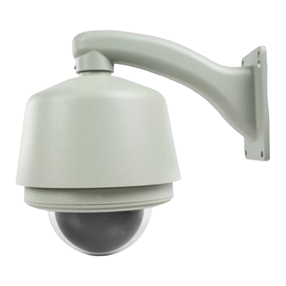
- Page 1 SEC-CAM901 SPEED DOME CAMERA...
- Page 2 SPEED DOME CAMERA Note:: • Read this manual carefully before installation and operation. Keep it handy for later reference.
-
Page 3: Table Of Contents
SPEED DOME CAMERA CONTENTS FEATURES ······························································2 BLC Mode···················································14 DECLARATION ······················································3 PAN/TILT PARAMETERS ·································14 Precaution····················································3 Auto Stop Time ········································14 Warnings ······················································3 Speed Amplify ··········································14 INSTALLATION PREPARATION·······················4 Proportional P/T·······································14 Tool List························································4 Set North ····················································14 Cables ···························································4 AUTO RUNNING ··················································15 Dip Switch Setting·····································4 Preset ··························································15 MOUNT TYPE ·························································5 Tour······························································15... -
Page 4: Features
SPEED DOME CAMERA FEATURES Product Features Multiple Integrated Camera/Optics Packages Graceful outlook, Vandal proof available System preheat in low temperature environment Programmable Multi-protocol 360° continuous pan, 180° Tilt “Auto Flip” 4 tours(27 presets/tour), 4 patterns, 4 cruise 8 titled zones Port for Software up-grade Built-in Alarm, 7 Inputs/2 Outputs Built-in Surge and Lightning Protection... -
Page 5: Declaration
SPEED DOME CAMERA Camera/Optics Image Sensor 1/4” Super HAD Resolution 480TVL Lens 22X f=3.6~79.2mm Digital Zoom 22X10 Angle of View 47°~2.2° Sync system Internal/external Min. Illumination 0.25Lux S/N Ratio >48db Iris Auto/Manual White Balance Auto/Manual Gain Auto AE Control Auto On/Off Privacy Mask Focusing system... -
Page 6: Installation Preparation
SPEED DOME CAMERA I N S T A L L A T I O N P R E P A T A T I O N TOOL LIST: Following tools may be needed for the installation: Screws and nuts Philips screw driver Standard screw driver Wire scissors Ladder... -
Page 7: Mount Type
SPEED DOME CAMERA MOUNT TYPE W A L L M O U N T... -
Page 8: Installation Guide
SPEED DOME CAMERA INSTALLATION GUIDE WALLMOUNT Check carefully to make sure the wall is firm and does not peel off. It is required that the wall can withstand 8 times weight of the dome set. 1. Mark mounting position 2. Install bracket. Use bracket to mark the mounting position on Conduct all cables through the hole of bracket, and wall... - Page 9 SPEED DOME CAMERA S W 1 S W 2 7. Down cover preliminary installation. 8. Install black liner and Pan/Tilt Module. Push the black liner into the two tabs. Install the pan/tilt Attach the safety chain with a M3 nut as picture module with two clips, match color of AMP sockets.
-
Page 10: System Connection
SPEED DOME CAMERA S Y S T E M C O N N E C T I O N... -
Page 11: Operation Instruction
SPEED DOME CAMERA OPERATION INSTRUCTION Speed dome can be driven through combination of hot keys on a keyboard controller. It can also be driven through OSD menu. OSD menu can be activated by preset #95 call or double calling preset 1 (call twice within 5 seconds). -
Page 12: Menu Operation
SPEED DOME CAMERA minute without any operation. All the settings will be saved automatically to protect against power outage. MENU OPERATION White Blance: Auto SELECTING ITEM BLC Mode In the main menu, the cursor flashes on the left Back side. Move the joystick up or down to point to the desired item. -
Page 13: System Info
SPEED DOME CAMERA SYSTEM INFO SYSTEM INFO Move the cursor to <Input S/N> and then move <Main Menu> <System > the joystick right, input the serial number according to the <Site S/N>, and then turn the Site Info joystick left to exit setting. Point cursor to <Back>, Display Setup and turn joystick right to exit. -
Page 14: Boot-Up Screen
SPEED DOME CAMERA <Zone Name> to access main menu or save preset through Choose to display the current zone title keyboard. NOTE: The dome’s default password is Select <Back> to return to upper menu 123456. Contact the supplier for the master BOOT-UP SCREEN password if forget the password after changing. -
Page 15: Lens Parameters
SPEED DOME CAMERA Back Select <System Reboot> to reboot the dome. Settings will not change after restarting LENS PARAMETERS automatically adjusts the focus to get the clear <Main Menu> <Lens> image. Focus can also be manually controlled by Digital Zoom : Off keyboard or matrix. -
Page 16: Camera Parameters
SPEED DOME CAMERA NOTE: Keep the default value is strongly <Main Menu> <Lens> < Iris ALC Value > recommended.. Set the iris average level control value. The value could be 000~255. Default value: 23X color/mono camera: 084 CAMERA PARAMETERS <Main Menu> <Camera>... -
Page 17: Auto Running
SPEED DOME CAMERA joystick to position north Auto Stop Time: Off When select <Set North>, following menu will Speed Amplify: Off pop out. Proportional P/T: Off Set North [Back] Select it to back to main menu. Back NOTE: Be better to set geographic north. AUTO RUNNING Remove Current <Main Menu>... -
Page 18: Cruise
SPEED DOME CAMERA each preset. Value ranges from 0~99. For example, NOTE: Camera pans only. DEFAULT DWELL: 001, all presets’ dwell time is set as 1 second, but user can still set NOTE: Zoom to desired level then run auto scan, independent dwell time for each preset in <Edit>... -
Page 19: Zone
SPEED DOME CAMERA <Record> Record pattern Set the position of the first point. The following picture shows the setting menu. <Test> Test recorded pattern Call Preset 1 To Confirm…….. <Run> Run Pattern until other command received <Back> Back to upper level menu <Speed>... -
Page 20: Alarm
SPEED DOME CAMERA [Pre 001~220] Call preset 001~220 Zone [Scan 001~004] Run auto scan 001~004 Park Time: 010 [Tour 001~004] Run tour 001~004 Park Action: Pat 001 [Pat 001~004] Run pattern 001~004 Back In this example, system will run Preset-8 after Preset 38 seconds of idle time Tour... - Page 21 SPEED DOME CAMERA Alarm in 4 : Tour 001 Alarm in 5 : Off Alarm in 6 : Off Alarm in 7 : Off Relay 1 : Off Relay 2 : Off Arm/Disarm: Arm Interval <S>: 004 Back In this example, when the first alarm is activated, the dome will run preset-100;...
-
Page 22: Appendix I: Dip Switch Setting
SPEED DOME CAMERA APPENDIX I: DIP SWITCH SETTINGS This is the guides for setting protocol, baud rate, dome address, video cable type, resistor jumper and alarm output. DIP Switches’ position The corresponding Dip-switches’ positions are shown below: This model of speed dome supports multi-protocol. The set-ting chart is shown below. -
Page 23: Address Setting Chart
SPEED DOME CAMERA and then set dome ID by controller (The Dome address setting dome SN number can be found on the side of the camera or on the package and The control commands contain target user manual.). dome’s ID. The dome only reacts to the 3. - Page 24 SPEED DOME CAMERA 4. Address setting chart Soft Soft...
- Page 25 SPEED DOME CAMERA Soft Soft...
-
Page 26: Resistor Jumper Setting
SPEED DOME CAMERA Soft Soft Resistor jumper setting Alarm output method setting There are two alarm output methods: NO and NC. NO means normal state is open RS485 bus needs two 120 _ resistors at both circuit, the circuit will be closed when an ends. -
Page 27: Transmission Chart
SPEED DOME CAMERA APPENDIX II: WIRE DIAMETER & TRANSMISSION CHART The transmission distance listed below are farthest ones recommended for each given wire diameter when the 24V AC voltage loss ratio is below 10% (for equipment powered by AC, the allowed maximum voltage voltage loss ratio is 10%). -
Page 28: Appendix Iii: Rs485 Bus Basic
SPEED DOME CAMERA APPENDIX III: RS485 BUS BASIC KNOWLEDGE Basic Property RS485 Bus is specified by RS485 standards. It is of half-duplex data transmission cables with characteristic impedance as 120. The maximum load capacity is 32 effective loads (including main controller and con- trolled equipment). -
Page 29: Protection
SPEED DOME CAMERA The dome 1. The RS485 Bus line is 1. Secure the can be not in good contact with connection. controlled the connectors. 2. Replace RS485 Bus but the 2. One wire of the RS485 wires. operation is Bus is broken. - Page 30 SPEED DOME CAMERA APPENDIX V: LIGHTNING PROOF & SURGE SIGNAL PROOF The product adopts TVS lightning proof technology to prevent from damage by lightning strike below 1500 W and impulse signals such as surge. But it is also necessary to abide by the following precautions to ensure electrical safety based on practical circumstances: Keep the communication cables at least 50 meters away from high voltage equipment or cables.
-
Page 31: Appendix Vi: Warranty
SPEED DOME CAMERA APPENDIX VI: WARRANTY 1. Scope The factory warrants its dome camera products to be free from defect in materials and workmanship for a period of one year from the date of purchase. During this period the factory will repair or replace components of the product which proves to be defective.
Need help?
Do you have a question about the SEC-CAM901 and is the answer not in the manual?
Questions and answers