
Related Manuals for Getinge 8666


Summary of Contents for Getinge 8666
- Page 1 SERVICE INSTRUCTIONS Washer disinfector Getinge 8666/8668 Mfg. no. SEV0320078- 5015108-00...
-
Page 3: Safety Regulations
Safety regulations Technical data Description Service instruction Getinge 8666/8668 Software description and settings Preventive maintenance Fault indications and troubleshooting Repair and adjustment We reserve the right to change without prior notice, our design and material specifications 5015108-00 2004-03-01... - Page 5 Safety regulations Safety regulations CONTENTS Safety regulations __________________________________________ 3 General safety regualtions __________________________________ 3 Product libaility __________________________________________ 3 Isolator switch ___________________________________________ 3 Attention symbols ________________________________________ 3 Service instructions Edition 0403 5015108-00...
- Page 6 Safety regulations Service instructions 5015108-00 Edition 0403...
- Page 7 Safety regulations Safety regulations This machine is designed with a number of built-in safety devices. To avoid injury, it is highly important not to bypass or disable these safety devices. General safety regulations • Take care when handling the chemical agent used in the machine. Read the details on the container or contact the manufacturer: - if agent comes into contact with the operator’s eyes or skin or if the vapours are breathed in, etc.
- Page 9 Technical data Technical data Contents Technical data ______________________________________________ 3 Alternative connection arrangements ___________________________ 4 Service instructions Edition 0403 5015108-00...
- Page 10 Technical data Service instructions 5015108-00 Edition 0403...
- Page 11 Technical data Technical data Weight incl. water chamber depth 720 mm 385-525 kg chamber depth 800 mm 385-525 kg Width 1110 m m Depth chamber depth 720 mm 910 m m chamber depth 800 mm 990 m m Height 1870 m m Environmental requirements: Air humidity max 80% at 31 °C Room temperature...
- Page 12 Technical data Alternative connection arrangements Service instructions 5015108-00 Edition 0403...
-
Page 13: Table Of Contents
Description Description Contents General ___________________________________________________ 3 Schematic diagram _________________________________________ 4 Electric heating ___________________________________________ 4 Steam heating ____________________________________________ 4 Steam and electric heating __________________________________ 5 Explanation of symbols _____________________________________ 5 Safe and simple ____________________________________________ 6 Simple service and installation ________________________________ 6 Door operation _____________________________________________ 6 Manually-operated door ____________________________________ 6 Automatically-operated door ________________________________ 7... -
Page 15: General
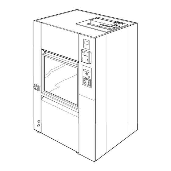
Description General The machine is a fully-automatic washer disinfector for cleaning and disinfecting goods in hospitals, laboratories and the pharmaceutical industry. The machine has two washing vanes and two dockings and can be equipped with several different accessories for different cleaning requirements. These accessories are presented in a special accessories catalogue. -
Page 16: Schematic Diagram
Description Schematic diagram Electric heating V1433 Steam heating V1434 Service instructions 5015108-00 Edition 0403... -
Page 17: Steam And Electric Heating
Description Steam and electric heating V1559 Explanation of symbols V1560 Service instructions Edition 0403 5015108-00... -
Page 18: Safe And Simple
Description Safe and simple The disinfector is controlled by a microprocessor. This has several advantages: • the built-in service program makes troubleshooting and servicing far easier • safety and reliability can be kept high by continuous monitoring of the process •... -
Page 19: Automatically-Operated Door
Description Automatically-operated door WhenVis pressed, the door is locked, the yellow lamp flashes and the program starts. When the program is complete, a green lamp lights up on both sides (if there are double doors) and the clean-side door opens automatically. When the door is fully open the green lamp goes out on both sides. -
Page 20: Drying
Description Drying The machine is equipped with a drying system as standard. Filter(s) Fans Hose for connection to pressure switch Non-return valve V1293 Heat exchangers Service instructions 5015108-00 Edition 0403... -
Page 21: Programs
Description Program The machine has an electronically programmable control system which can hold up to 10-15 programs. Six of these programs can be started with the program selection buttons. With 1-6 you can choose up to six programs. If the control system has more programs, the subsequent ones are chosen from a scrollable list. -
Page 22: Abort At Start Of Process
Description CW+HW HW HW option) V1513 Program phases Pre-rinse 1 Alkaline detergent Pre-rinse 2 Neutralisation Wash Instrument milk (extra equipment) Neutralize If instrument milk is Post-rinse 1 does, neutralisation is Post-rinse 2 not dosed. Final rinse Disinfection Drying Abort at start of process A started program can be aborted within ten seconds of the door locking. -
Page 23: Fast-Stepping A Program
Description Fast-stepping a program All safety functions are disabled for fast stepping. Fast stepping must only be used during servicing. Never stop fast stepping in a heating phase. If you do, the machine may be damaged. An ongoing program can be fast-stepped phase by phase. Fast stepping can be chosen during an ongoing process. - Page 25 Software description and settings Software description and settings Contents Description ________________________________________________ 3 Control panel ______________________________________________ 4 Display _________________________________________________ 4 Program selection buttons __________________________________ 4 Menu tree navigation buttons _______________________________ 5 Scroll in menus and lists _____________________________________ 5 Field editing _______________________________________________ 5 Password _________________________________________________ 6 Operator ________________________________________________ 6 Parameter ________________________________________________ 6...
-
Page 27: Description
Software description and settings Description This section describes the PACS 300 control and monitoring system. PACS 300 is an electronic system that is used to control the various functions of the washer-disinfector. The letters PACS stand for Programmable Autoclave Control System. The purpose of the control system is to issue orders and send them to the executive components of the washer-disinfector so that a number of process steps can be performed in accordance with a predetermined template. -
Page 28: Control Panel
Software description and settings The control panel The buttons on the control panel are used to choose programs, navigate the menu tree, acknowledge error codes, etc. Display Buttons for menu tree navigation Program selection buttons Acknowledgement of error message Indicator lamps Start wash program V1363... -
Page 29: Scroll In Menus And Lists
Software description and settings Buttons for menu tree navigation The are five buttons for navigating the panel. These fixed buttons are four arrow buttons that control the cursor (I, K, J and H) and S. Used to go back one step (up one level) in menus. If the button is held down for a little longer, you are returned to the main menu. -
Page 30: Password
Software description and settings Passwords There are five passwords with different levels of authorisation in the system program. The operator password has the lowest authority; the programming password has full authority. The following password levels are as follows: • Operator – code 558387. •... -
Page 31: Service
Software description and settings Service Code in Authority to change menu tree Parameters: Calendar (time and date) Sensor calibration Service messages DIP switches Non-critical system configurations. Process-critical configurations, parameters of type P. Password configuration Documentation Programming Code in Authority to change menu tree Parameters: Calendar (time and date) - Page 32 Preventive maintenance Preventive maintenance Contents General ___________________________________________________ 3 Periodic maintenance _______________________________________ 3 Function check _____________________________________________ 4 Instructions, cable, switch __________________________________ 4 Filter and valves __________________________________________ 4 Controls ________________________________________________ 4 Insert for goods __________________________________________ 4 Door ___________________________________________________ 5 Detergent dosing _________________________________________ 5 Washing system __________________________________________ 5 Temperature control _______________________________________ 5 Dryer ___________________________________________________ 5...
-
Page 34: General
Preventive maintenance General The required maintenance interval will depend largely on the quality of the incoming water and how often the machine is used. The maintenance will have to be determined in each individual case. We recommend that the stated maintenance operations are done at the specified intervals. We also recommend that a function check is done once or twice a year. -
Page 35: Function Check
Preventive maintenance Function check This must only be done by authorised personnel. The machine is connected to the electricity supply and some components are live. Instructions, cable, switch • Check that a goods placing sign has been put up on the wall behind the disinfector. •... -
Page 36: Door
Preventive maintenance Door Check that the door seal closes tight and is undamaged and that there is no leakage while a program is running. Clean or replace the seal if necessary. Detergent dosing Check that the suction hose and pump are full of detergent or rinse-aid before running a program. - Page 38 Fault indications and troubleshooting Fault indications and troubleshooting Contents Fault indications ___________________________________________ 3 A red lamp lights up _______________________________________ 3 Messages _______________________________________________ 3 Fault codes ______________________________________________ 4 Acknowledging a fault code _________________________________ 4 Troubleshooting ____________________________________________ 5 Service instructions Edition 0403 5015108-00...
-
Page 40: Fault Indications
Fault indications and troubleshooting Fault indications Fault message or fault code Add detergent 1 Red lamp: Disinfection not achieved V1363 A red lamp lights up If the red lamp at O lights up, the process has been aborted because of a fault. Call service personnel. -
Page 41: Fault Codes
Fault indications and troubleshooting Error codes P02 OP-D F00 POWER FAIL Fault codes indicate that a serious fault has occurred in the washing process. The fault must be put right by an authorised service technician. Acknowledging a fault code Reset the fault code by: 1. -
Page 42: Troubleshooting
Fault indications and troubleshooting Troubleshooting The table below describes the fault codes that may be generated and a possible action for each fault code. This may only be done by authorised personnel. The machine is connected to the electricity supply and some components are live. Fault code Fault Comment Power failure... - Page 43 Fault indications and troubleshooting Fault code Fault Comment Fault door, dirty side The door does not unlock (-S01) within 10 seconds. Possible action: a. Check whether the microswitch (-S01) for the “door open” limit position has been activated within 10 seconds on door unlocking. b.
- Page 44 Fault indications and troubleshooting Fault code Fault Comment Faulty door, clean side The door does not open (-S08) within 20 seconds. (Machine with automatic door only.) Possible action: a. Check that nothing is trapped in the door. b. Check whether the microswitch (-S08) for closed door limit position has been activated for 20 seconds.
- Page 45 Fault indications and troubleshooting Fault code Fault Comment Booster tank slow to fill If filling (-B11) takes longer than 10 minutes, a fault code is generated. Possible action: a. Check that the shutoff valves are open and that water is reaching the machine. b.
- Page 46 Fault indications and troubleshooting Fault code Fault Comment Faulty temperature sensor in washing chamber Independent. The temperature (-B07) is <0 °C or >130 °C. Possible action: a. Check the temperature sensor (for open-circuit or short-circuit) Faulty temperature sensor in dryer The temperature (-B05) is <0 °C or >130 °C.
- Page 48 Repair and adjustment Repair and adjustment Contents Connecting a PC ____________________________________________ 3 Connecting a barcode scanner _________________________________ 4 Handscanner ____________________________________________ 4 Barcode scanner _________________________________________ 5 Loading a program to flash memory _____________________________ 6 Loading system programs __________________________________ 6 Load language files _______________________________________ 8 Cold start ________________________________________________ 11 Calibration _______________________________________________ 12 Conductivity meter ______________________________________ 12...
- Page 49 Repair and adjustment Service instructions 5015108-00 Edition 0403...
-
Page 50: Connecting A Pc
Repair and adjustment Connecting a PC An RS-232 cable is needed to connect a PC to the washer-disinfector. Proceed as follows: 1. Connect a cable between the PC and port X24 or X25 as shown below. - X24 is mainly used for a PC and (for example) a scanner. - X25 is used mainly for T-doc (RS485) and printer (RS232 or RS485). -
Page 51: Connecting A Barcode Scanner
Repair and adjustment Connecting a barcode scanner Handscanner To connect a barcode scanner, proceed as follows. 1. Connect power to the scanner. 2. Calibrate the scanner by scanning in the barcodes below. Scan in the top barcode. Wait for a beep, then scan in the next code. -
Page 52: Barcode Scanner
Repair and adjustment Barcode scanner To connect a barcode scanner, proceed as follows. 1. Connect power to the scanner. 2. Connect a communication cable between the scanner and port X24. 3. Set type of communication. The communication settings are done in the service program; see under tab 5 Software description and settings. -
Page 53: Loading A Program To Flash Memory
The flash memory can be loaded with new wash programs or new system programs. Loading new wash programs requires the CS-1000 program, which can be purchased from Getinge. Instructions are supplied with CS-1000. System programs and language versions are loaded with Flashloader. - Page 54 Repair and adjustment 7. Switch on the power to the machine with the main switch. The display should now show: GETINGE Ram OK GETINGE PACS 300 Version X.XX (XXXX) 8. Start Flashloader from PC. 9. Set up as shown. V1578 File name Choose the right program file (*.a37).
-
Page 55: Load Language Files
Repair and adjustment 11. When loading is complete, the following image appears. Press OK. V1580 12. Now the display shows: SW Update 0x2497 Updating CRC..A beep is heard and the display shows: SW Update 0x2497 CRC OK 13. Check that the battery jumper (X30) is set to ON. 14. - Page 56 Repair and adjustment 6. Change the jumper (X29) on the board for the PACS 300 control system from Normal to Test. V1544 7. Set up as shown. V1578 File name Choose the right program file (*.a37). Com Port The port to which you connected the data cable to your PC. Baudrate Choose 57600 All Sectors and Verbose must be checked (=selected).
- Page 57 Repair and adjustment 8. Choose the Language tab. V1581 9. Choose the relevant files: - Language support file, - Language file for PACS database. 10. Set Flash Sector for Language to 8 and 10 (as shown). 11. Check (select) Transfer. 11.
-
Page 58: Cold Start
Repair and adjustment Cold start Do a cold start when the machine has hung and you cannot proceed with the program. Switch off the power to the machine. Move the battery jumper (X30) to Off. Move the programming jumper (X29) from Normal to Cold. Switch on the power. -
Page 59: Calibration
Repair and adjustment Calibration Conductivity meter Check the output signal from conductivity meter To check the output signal, proceed as follows. 1. Press [ on the conductivity meter. 2. Enter code 22 with Y and Z. 3. Press [. Setup 1 appears. 4. -
Page 60: Calibration
Repair and adjustment Calibration To calibrate the conductivity meter, proceed as follows. 1. Connect a PC with the CS 1000 program installed to the disinfector. 2. Press [ on the conductivity meter. 3. Enter code 22 with Y and Z. 4. - Page 61 Repair and adjustment 13.Click Conductivity (A) and then Calibrate (B). V1564 14.Enter the value 0 (A) and click Set Low. V1565 Service instructions 5015108-00 Edition 0403...
- Page 62 Repair and adjustment 15. Set 20 mA on the conductivity meter with Y and Z. 16. Enter 200 (A) in CS 1000 and click Set High. V1566 17. Check that the value (B) rises to 200. 18. Log off CS 1000. 19.
-
Page 63: Pressure Sensor For Circulation Pump
Repair and adjustment Pressure sensor for circulation pump To calibrate the pressure sensor for the circulation pump, proceed as follows. 1. Connect a PC with the CS 1000 program installed to the disinfector. 2. Connect a process simulator to A01-X2; + to 2 - to 5. - Page 64 Repair and adjustment 6. Enter the value 0 (A) and click Set Low. V1568 7. Set the process simulator to 20 mA. 8. Enter 160 (A) in CS 1000 and click Set High. V1569 9. Check that the value (B) rises to 160. 10.
-
Page 65: Temperature Sensor - With Resistor
Repair and adjustment Temperature sensor – with resistor Proceed as follows to calibrate the temperature sensors with the aid of resistors: 1. Connect a PC with the CS 1000 program installed to the disinfector. 2. Insert resistors for 20 ºC at the following places: A01-X7 Chamber temperature (two sensors) A01-X6... - Page 66 Repair and adjustment 5 Enter the value 20 (A) and click Set Low. V1571 6 Check that the value (B) rises to 20. 7 Replace resistors for 20 ºC with resistors for 90 ºC. 8 Enter 90 (A) in CS 1000 and click Set High. V1572 9.
-
Page 67: Temperature Sensors - With Ice Bath And Oil Bath
Repair and adjustment Temperature sensors – with ice bath and oil bath Proceed as follows to calibrate the temperature sensors with the aid of resistors: 1. Connect a PC with the CS 1000 program installed to the disinfector. 2. Prepare an ice bath and an oil bath. The ice bath must consist of crushed ice in a bowl of cold water. - Page 68 Repair and adjustment 7 Check that the reading of the external thermometer stabilises. Enter the reading of the external thermometer (A) and click Set Low. V1571 8 Check that the value (B) rises to the set value. 9 Move the temperature sensors and the external thermometer to the oil bath. Check that the reading of the external thermometer stabilises.
-
Page 69: Differential Pressure Gauge For Dryer
Repair and adjustment Differential pressure gauge for dryer To calibrate the differential pressure gauge for the dryer, proceed as follows. 1. Connect a PC with the CS 1000 program installed to the disinfector. 2. Close the machine doors. 3. Connect an external differential pressure gauge in parallel with the existing gauge on the machine. - Page 70 Repair and adjustment 6. Enter the value 0 (A) and click Set Low. V1574 7. Start the machine fan manually as follows: >SETUP Scroll to SETUP with J. Press S. >SYSTEM ABOUT Scroll to SYSTEM with J. Press S. >ENTER PASSWORD Enter password.
- Page 71 Repair and adjustment >01 FAN SPEED 100% Scroll to 01 FAN SPEED with J. Press S. >01 FAN SPEED Change AUT to MAN with K. Set fan speed to 75 %. 8. Check that the reading of the external differential pressure gauge stabilises. Enter the reading of gauge (A) in CS 1000 and click Set High.
-
Page 72: Replacing A Temperature Sensor
Repair and adjustment Replacing a temperature sensor This must only be done by authorised personnel. The machine is connected to the electricity supply and some components are live. In wash chamber and dryer • Remove the old temperature sensor by pulling it out of the seal. •... -
Page 73: Door
Repair and adjustment Door Position and operation, door switches This must only be done by authorised personnel. Before starting work, make sure that the machine is isolated from the electric power supply. The illustration show which door switches are fitted to the machine with manual or automatic door. Door switch DOOR UNLOCKED... - Page 74 Repair and adjustment Safety switch Door switch DOOR UP DOOR UNLOCKED Door switch DOOR LOCKED Safety switch DOOR DOWN Door switch DOOR CLOSED V1297 Door switch DOOR OPEN Automatic door: When the door is at its bottom position, the DOOR OPEN switch is activated and when the door is in the top position the DOOR CLOSED and DOOR UNLOCKED switches are activated.
-
Page 75: Adjusting Door Switches
Repair and adjustment Adjusting door switches This must only be done by authorised personnel. Before starting work, make sure that the machine is isolated from the electric power supply. Check that the respective microswitches are activated. Adjust if necessary. Door switch DOOR CLOSED Safety switch Door switch... -
Page 76: Adjusting Door Up Safety Switch
Repair and adjustment Adjusting DOOR UP safety switch This may only be done by authorised personnel. The DOOR UP safety switch is fitted only to machines with automatic door. To prevent damage, the spring must be adjusted so that the door stops when a force of 150 N is applied to the door when the door is moving up. -
Page 77: Replacing The Door Seal
Repair and adjustment Replacing the door seal This must only be done by authorised personnel. • Automatic door: Remove door switches and bolts. (If a loading/unloading unit is installed, there are door switches on the left-hand side only). This is so that the door can be pushed down far enough to release the seal. -
Page 78: Removing The Door
Repair and adjustment Removing the door This must only be done by authorised personnel. • Remove the front panels. • Automatic door: Remove door switches and the door switches of the loader/unloader (if there is one). Remove bolts. • Remove leaf springs, bolts and spacers in the lower part of the frame. •... -
Page 79: Adjusting The Door Closing Force
Repair and adjustment Adjusting the door closing force This must only be done by authorised personnel. When door is in its top position, the motor pulls the door in from the outer to the inner position. The force with which it does this is adjusted with a spring as shown below. Note: The spring must never fully compressed. -
Page 80: Adjusting Manual Door
Repair and adjustment Adjusting manual door This must only be done by authorised personnel. The door is held in its bottom position by two leaf springs. When the door is pushed up, it must stop about 10 cm from its top position. The door must always be moved up manually for the last part of its travel. -
Page 81: Overheat Protection
Repair and adjustment Overheat protection If the element overheats, the overheat protection trips. Reset the overheat protection with button A. V1297 V767 Service instructions 5015108-00 Edition 0403... -
Page 82: Cleaning The Filters In The Solenoid Valves
Repair and adjustment Cleaning the filters in the solenoid valves This must only be done by authorised personnel. The machine is connected to the electricity supply and some components are live. The filters in the solenoid valves should be regularly checked and cleaned if necessary. V1584 Service instructions Edition 0403... -
Page 83: Dryer
Repair and adjustment Dryer This must only be done by authorised personnel. The machine is connected to the electricity supply and some components are live. V1292 V1297 Temperature sensor located inside the tube • Check seals and hoses for leaks once a year. •... -
Page 84: Conductivity Measurement (Extra Equipment)
Repair and adjustment Conductivity measurement (extra equipment) Conductivity is measured with equipment from Endress+Hauser. This must only be done by authorised personnel. Function in washing process The conductivity meter monitors the quality of the water in the final rinse, independently of the process control. -
Page 85: Setting Detergent And Rinse-Aid Quantities
Repair and adjustment Setting detergent and rinse-aid quantities This must only be done by authorised personnel. The machine is connected to the electricity supply and some components are live. • Dispense 100 ml of the relevant substance into a measuring beaker. Check that the suction hose and pump are full before the check. -
Page 86: Printer (Extra Equipment)
Repair and adjustment Printer (extra equipment) Replacing the paper roll • Open the front. • Remove any paper residue. • Remove the ink ribbon by pressing gently on the left-hand side of the ribbon cassette. • Cut the end of the new roll at the angle shown in the illustration below. This makes it easier to thread the paper into the mechanism. -
Page 87: Ribbon Cartridge Replacement
Repair and adjustment Ribbon cartridge replacement • Open the front. • Remove the ink ribbon by pressing gently on the left-hand side of the ribbon cassette. • Replace the ribbon cassette. The printer is now ready to use again. Jumpering an expansion card The reason for jumpering expansion cards is to enable the processor to identify which card is which. - Page 88 Repair and adjustment Exp.1 (A02*) Exp. 2 (A03*) Exp. 3 (A04*) V1543 *References on electrical diagram Service instructions Edition 0403 5015108-00...
-
Page 89: Replacing A Hose To A Hose Pump
Repair and adjustment Replacing a hose to a hose pump This may only be done by authorised personnel. Before starting work, make sure that the machine is isolated from the electric power supply. • Remove the cover (3) by unscrewing screw A. •... -
Page 90: Booster Tank
Repair and adjustment Booster tank The booster tank contains hot water. This may cause scalding injuries if proper procedures are not followed. It is essential to drain the booster tank when servicing the booster tank and its valves. This is in order to prevent scalding, since the temperature of the water in the booster tank is about 85 degrees Celsius (about 180 degrees F) Booster tank with drain tap... - Page 91 Repair and adjustment Drain tap Level sensor Micro switch Plug DW-valve Steam valve Steam trap Drain tap Level sensor Micro switch Plug DW-valve Service instructions 5015108-00 Edition 0403...
-
Page 92: List Of Components
Repair and adjustment List of components T02-F01 A01-F01 JB01 JB02 B01:1 B01:2 V1482 Service instructions Edition 0403 5015108-00... - Page 93 Repair and adjustment Control system PACS300 Contactor, tank heating A01-F01 Glass fuse for main board power supply T Contactor, dryer heating (1) 315 mA/250 V Contactor, booster tank heating * Expansion card 1 Motor, circulation pump Expansion card 2 Motor, waste pump Expansion card 3 Motor, dosing pump 1 Panel, dirty side...
- Page 94 Repair and adjustment V1483 * Optional extra equipment Panel, clean side * Motor, door, clean side * Motor, door locking, clean side * Limit switch, door locked/in, clean side * Limit switch, door unlocked/out, clean side * Limit switch, top position/closed, clean side * Limit switch, bottom position/open, clean side * Limit switch, door locking, clean side * Limit switch, door locking, clean side *...
- Page 135 This product is manufactured by: GETINGE DISINFECTION AB, Ljungadalsgatan 11, Box 1505, 351 15 Växjö, Sweden...