Sign In
Upload
Manuals
Brands
York Manuals
Chiller
YZ MODEL A
York YZ MODEL A Manuals
Manuals and User Guides for York YZ MODEL A. We have
1
York YZ MODEL A manual available for free PDF download: Operation And Maintenance Manual
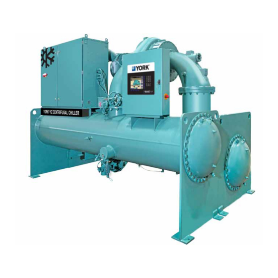
York YZ MODEL A Operation And Maintenance Manual (170 pages)
MAGNETIC BEARING CENTRIFUGAL CHILLER WITH OPTIVIEW CONTROL CENTER
Brand:
York
| Category:
Chiller
| Size: 10.12 MB
Table of Contents
Table of Contents
6
Section 1 - System Fundamentals
11
System Components
11
FIGURE 1 - YZ Chiller Components (Rear)
12
FIGURE 2 - YZ Chiller Components (Front)
12
FIGURE 3 - Optiview Control Center
13
System Operation
15
Water Circuits
17
FIGURE 4 - Refrigerant Flow-Thru Chiller
19
Section 2 - System Operating Procedures
21
Pre-Starting
21
Start-Up
21
Chiller Operation
22
Chilled Liquid Control Settings
22
TABLE 1 - Input Current Limit Threshold
22
Operator Setpoints Quick Reference
23
TABLE 2 - Temperature Setpoint
23
TABLE 3 - Input Current Limit Threshold
23
Stopping the System
24
Safety Stop
24
Operating Logs
24
FIGURE 5 - Liquid Chiller Log Sheets
24
Fault Shutdowns
25
Prolonged Shutdown
25
Restart after Prolonged Shutdown
25
Section 3 - Optiview™ Control Center Functions and Navigation
27
Interface Conventions
27
Languages
29
Analog Input Ranges
29
TABLE 4 - Analog Input Ranges
29
FIGURE 6 - Home Screen
30
FIGURE 7 - System Screen
32
FIGURE 8 - Evaporator Screen
34
FIGURE 9 - Condenser Screen
36
FIGURE 10 - Purge Screen
38
FIGURE 11 - Compressor Screen
40
FIGURE 12 - Capacity Control Screen
42
FIGURE 13 - Magnetic Bearing Controller (MBC) Screen
45
FIGURE 14 - Surge Protection Screen
47
FIGURE 15 - Variable Geometry Diffuser (VGD) Screen
49
FIGURE 16 - Motor Details Screen
50
FIGURE 17 - UPS Screen
52
FIGURE 18 - Motor - Variable Speed Drive (VSD) Screen
54
FIGURE 19 - Variable Speed Drive (VSD) Details Screen
56
FIGURE 20 - Harmonic Filter Details Screen
58
FIGURE 21 - Setpoints Screen
60
FIGURE 22 - Setup Screen
62
FIGURE 23 - Schedule Screen
64
FIGURE 24 - User Screen
66
FIGURE 25 - Comms Screen
67
FIGURE 26 - Printer Screen
68
FIGURE 27 - Sales Order Screen
70
FIGURE 28 - Operations Screen
72
FIGURE 29 - Remote Control Screen
73
FIGURE 30 - History Screen
74
FIGURE 31 - History Details Screen
76
FIGURE 32 - Custom Screen
77
FIGURE 33 - Custom Setup Screen
78
FIGURE 34 - Trend Screen
80
FIGURE 35 - Trend Setup Screen
82
FIGURE 36 - Advanced Trend Setup Screen
84
FIGURE 37 - Common Slots Screen
86
Master Slot Numbers List for Use with Trend Feature
87
Display Messages
90
TABLE 5 - Status Messages
90
TABLE 6 - Run Messages
91
TABLE 7 - MBC Startup Messages
91
TABLE 8 - Start Inhibit Messages
91
TABLE 9 - Warning Messages
92
TABLE 10 - Routine Shutdown Messages
94
TABLE 11 - Cycling Shutdown Messages
95
TABLE 12 - Safety Shutdown Messages
101
Section 4 - Vsd Operation
107
PYT Model VSD Overview
107
PYT Model VSD Components
107
PYT Model VSD (330, 420, 780, 1020 & 1280 Amp)
108
Harmonic Filter Option
108
Critical Load Power
109
FIGURE 38 - Drive Cabinet Door (PYT330, PYT420, PYT780 & PYT1020)
110
FIGURE 39 - Drive Cabinet Door (PYT1280)
110
FIGURE 40 - Drive Cabinet Model PYT330
111
FIGURE 41 - Drive Cabinet Model PYT420
111
FIGURE 42 - Left Side of Drive Cabinet Model PYT780
112
FIGURE 43 - Right Side of Drive Cabinet Model PYT780
113
FIGURE 44 - Left Side of Drive Cabinet Model PYT1020
114
FIGURE 45 - Right Side of Drive Cabinet Model PYT1020
115
FIGURE 46 - Left Side of Drive Cabinet Model PYT1280
116
FIGURE 47 - Right Side of Drive Cabinet Model PYT1280
117
Section 5 - Maintenance
119
Preventative Maintenance
119
TABLE 13 - Maintenance Requirements
119
Renewal Parts
120
Operating Inspections
120
Checking System for Leaks
120
Conduct Pressure Test
120
System Evacuation
121
Vacuum Dehydration
121
FIGURE 48 - Evacuation of Chiller
122
TABLE 14 - System Pressures
122
FIGURE 49 - Saturation Curve
123
Conduct Pressure Test
124
Refrigerant Charging
124
Checking the Refrigerant Charge
124
Handling Refrigerant for Dismantling and Repairs
125
Compressor and Motor
125
Condensers and Evaporators
125
TABLE 15 - Approximate Refrigerant and Water Weight
125
Electrical Controls
127
Automatic Battery Health Test - During Shutdown
128
Section 6 - Printing
129
Printing Overview
129
Downloading System Prints to Alaptop
129
FIGURE 50 - Communications Block Diagram
131
FIGURE 51 - Optiview Panel to PC Serial Cable
131
FIGURE 52 - Sample Printout (Status or History)
132
FIGURE 53 - Sample Printout (Setpoints)
133
FIGURE 54 - Sample Printout (Schedule)
135
FIGURE 56 - Sample Printout (Security Log Report)
136
Section 7 - Decommissioning, Dismantling, and Disposal
139
Temperature
140
TABLE 16 - si Metric Conversion
140
Appendix - Material Safety Data Sheets
141
Advertisement
Advertisement
Related Products
York YZ
York Millennium YCAS0440EC
York Latitude YCIV0207S
York Millennium YCAS 0773
York YHAU-CGN-1100EXWH
York MILLENNIUM YCAR0645
York YCAV0739
York YCAV0287P
York YGWH 330
York YCAV1549
York Categories
Air Conditioner
Heat Pump
Chiller
Furnace
Air Handlers
More York Manuals
Login
Sign In
OR
Sign in with Facebook
Sign in with Google
Upload manual
Upload from disk
Upload from URL