Sign In
Upload
Manuals
Brands
York Manuals
Chiller
YVWA
York YVWA Manuals
Manuals and User Guides for York YVWA. We have
2
York YVWA manuals available for free PDF download: Installation Operation & Maintenance, Manual
York YVWA Installation Operation & Maintenance (156 pages)
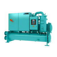
WATER-COOLED SCREW LIQUID CHILLERS, SINGLE COMPRESSOR 50 HZ AND 60 HZ, 125 - 200 TON, 440 - 700 KW
Brand:
York
| Category:
Chiller
| Size: 12.88 MB
Table of Contents
Table of Contents
5
Section 1 - General Chiller Information and Safety
11
Introduction
11
About this Manual
11
Warranty
11
Quality Assurance
11
Fluorinated Greenhouse Gases
12
Responsibility for Safety
12
Misuse of Equipment
12
FIGURE 1 - Emergency Shutdown Handle
13
Section 2 - Product Description
15
Components
15
FIGURE 2 - YVWA Chiller Major Components (Front View)
16
FIGURE 3 - YVWA Chiller Major Components (Rear View)
17
FIGURE 4 - Basic System Control and VSD System Architecture
18
Semi-Hermetic York Screw Compressors
19
Evaporator
19
Condenser
19
Refrigerant Circuit
19
Complete Factory Package
19
Electrical
19
Building Automation System Capabilities
19
Microcomputer Control Center
20
Options
20
FIGURE 5 - Control Center User Interface
20
FIGURE 6 - Head Pressure Control System
22
Section 3 - Handling, Storage, Installation and Reassembly
23
Shipment and Storage
23
Inspection, Damage, and Shortage
25
Lifting Weights
26
TABLE 1 - Unit Weight
26
Moving the Chiller for Forms 1 and 2
27
FIGURE 7 - Unit Rigging for Forms 1 and 2
27
Foundation
28
Clearance for Service
28
FIGURE 8 - Service Clearance Requirements
28
TABLE 2 - Service Clearance Requirements
28
Installing Elastomeric Vibration Isolator Pads
29
FIGURE 9 - Elastomeric Vibration Isolator Pad Mounts (Standard) - Inches (MM)
29
Installing Optional Spring Isolators
30
FIGURE 10 - Spring Isolators - Inches (MM)
30
Form 7 Reassembly
31
TABLE 3 - Evaporator and Condenser Weight (Lb/Kg)
31
TABLE 4 - Torque Specification
32
FIGURE 11 - Rigging the Evaporator
33
TABLE 5 - Evaporator Dimensions (In/MM)
33
FIGURE 12 - Condenser Rigging
34
TABLE 6 - Condenser Dimensions (In/MM)
34
FIGURE 13 - Isolator Installation
35
FIGURE 14 - Heat Exchanger Shipping Brackets
37
FIGURE 15 - Heat Exchanger Pipes
37
FIGURE 16 - Liquid Injection Piping
38
FIGURE 17 - Filter Drier and Piping
38
FIGURE 18 - Driveline (Compressor/Motor) Assembly
39
TABLE 7 - Compressor Weight and Dimensions
39
TABLE 8 - Oil Separator Weight and Dimensions on Single Compressor Units
40
FIGURE 19 - Oil Separator Discharge Piping on Single Compressor Units
41
FIGURE 20 - Transducer, Eductor and Oil Return Piping
42
FIGURE 21 - Oil Supply Piping
42
TABLE 9 - VSD Weight and Dimensions
43
FIGURE 22 - Variable Speed Drive (VSD)
44
FIGURE 23 - Control Panel
45
FIGURE 24 - VSD Cooling Hoses
45
Piping Joint Assembly
46
Pipe Thread Joints
46
FIGURE 25 - Alternate Piping for VSD
46
TABLE 10 - Assembly Compounds
46
Gasket Joints
47
FIGURE 26 - Torque Pattern
47
TABLE 11 - ANSI 150 Lb Flange Torque Specifications
47
TABLE 12 - ANSI 300 Lb Flange Torque Specifications
47
Torque Values
48
Refrigerant Tubing Reassembly
48
FIGURE 27 - Adjustable End Fitting
48
TABLE 13 - SAE J429 Gr 5 Bolts Torque Specifications
48
FIGURE 28 - Back off Locknut
49
FIGURE 29 - Screw Fitting into Port
49
FIGURE 30 - Torque Fitting
49
FIGURE 31 - SAE or ISO 6149 Straight Thread O-Ring Port
49
Brazed Joints
50
TABLE 14 - Assembly Torque Metric for Metric Tube Fittings
50
FIGURE 32 - Brazed Joints
51
TABLE 15 - O-Ring Assembly Torque Specifications
51
TABLE 16 - Brazed Joints
51
Piping Connections
52
Check for Piping Alignment
52
Condenser and Chilled Liquid Piping
52
General Requirements
52
Water Treatment
53
Pipework Arrangement
54
Minimum Water Volume
54
Leaving Water Temperature out of Range
54
FIGURE 33 - Schematic of a Typical Piping Arrangement
54
TABLE 17 - Water Volume for Applications
54
TABLE 18 - Evaporator and Condenser Water Capacity (Gal/L)
54
Nozzle Connections
55
Options for Flanges
55
Refrigerant Relief Piping
55
FIGURE 34 - Leaving Water Temperature Out-Of-Range Suggested Layout
55
FIGURE 35 - Victaulic Groove
55
FIGURE 36 - Flange Attachment
55
FIGURE 37 - Typical Components of Relief Piping
56
TABLE 19 - Refrigerant Relief Characteristics (Per Valve)
56
Unit Piping
57
Electrical Connection
57
Power Wiring
57
Power Supply Wiring
57
115VAC Control Supply Transformer
57
Control Wiring
57
System Inputs
58
Analog Inputs
58
FIGURE 56 - Options Key
58
TABLE 20 - System Input Connections
58
FIGURE 38 - Power Connections
62
TABLE 21 - Lug Data (UL/ASME/CE) - Pin 22/Power Field
63
TABLE 22 - Lug Data (GB) - Pin 22/Power Field
63
TABLE 23 - Voltage Variations
63
Section 4 - Technical Data
65
TABLE 24 - Complete Pin Number Description
65
FIGURE 39 - Single Compressor Unit Dimensions
72
Single Compressor Unit Dimensions
72
Dimensions of Evaporator Nozzle Arrangements
74
FIGURE 40 - Evaporators - Compact Water Boxes (2-Pass)
74
FIGURE 41 - Evaporators - Compact Water Boxes (3-Pass)
74
TABLE 25 - Evaporator Nozzle Dimensions - in (MM)
74
Dimensions of Condenser Nozzle Arrangements
75
FIGURE 42 - Condensers - Compact Water Boxes (1-Pass)
75
FIGURE 43 - Condensers - Compact Water Boxes (2-Pass)
75
FIGURE 44 - Condensers - Compact Water Boxes (3-Pass)
75
TABLE 26 - Condenser Nozzle Dimensions - in (MM)
75
TABLE 27 - Water Flow Rate Limits GPM (L/S) (Based Upon Standard Tubes at Design Full Load Conditions)
76
Section 5 - Commissioning
77
Preparation
77
First Time Start-Up
77
Section 6 - Operation
83
Operating Controls
83
FIGURE 45 - Keypad and Display
83
Basic Operating Sequence
84
FIGURE 46 - Control Operation
85
TABLE 28 - Load Limiting Values
86
User Interface
88
FIGURE 47 - Status Key
89
Fault Messages
91
Microboard (331-03478-XXX)
91
FIGURE 48 - New 331-03478-XXX Microboard
92
Program Update
93
TABLE 29 - Flash Card Update Error XXXXX
93
Data Logging
94
TABLE 30 - Data Logging
94
TABLE 31 - Unit Warnings
95
TABLE 32 - Unit Safeties (Faults)
97
TABLE 33 - System Safeties (Faults)
99
TABLE 34 - HPCO Mechanical Cutouts
101
TABLE 35 - Timer Settings
101
FIGURE 49 - Unit Data Key
104
FIGURE 50 - System Data Key
105
TABLE 36 - Sensor Minimum/Maximum Outputs
106
FIGURE 51 - VSD Data and Operating Hours/Start Counter Keys
107
FIGURE 52 - History Key
108
FIGURE 53 - Setpoints Key
110
FIGURE 54 - Setpoint High and Low Limits Defined by Control Range (CR)
111
TABLE 37 - Setpoint Values
111
FIGURE 55 - Program Key
112
TABLE 38 - Program Limits
113
TABLE 39 - Setup Mode Programmable
116
FIGURE 57 - Date/Time and Schedule Key
120
FIGURE 58 - Manual Override and Print Key
122
FIGURE 59 - Printer Cable Connection from YVWA Chiller to a Computer
122
Acceptable Printers
123
Printer Connections
123
Printer Setup
123
FIGURE 60 - Printer Cable Connection from YVWA Chiller to a Serial Printer
123
TABLE 40 - Okidata OKIPOS 441
123
Printing a Report
124
TABLE 41 - Printout Types
124
FIGURE 61 - Sample Printout
125
FIGURE 62 - System Switches and Service Keys
127
BAS Communications
128
FIGURE 63 - E-Link Gateway Option
128
TABLE 42 - Real Time Number Errors
129
Section 7 - Maintenance
131
General Requirements
131
TABLE 43 - Operation/Inspection /Maintenance Requirements for YVWA Chillers
131
Daily Operating Inspections
132
Compressor Oil
132
TABLE 44 - Compressor Oil Limits
133
FIGURE 64 - Charging Oil
134
Oil Filter Replacement
135
FIGURE 65 - Oil Filter Assembly
135
FIGURE 66 - Oil Eductor Assembly
136
Refrigerant Charging
137
Handling Refrigerant for Dismantling and Repairs
137
Checking System for Leaks
138
Refrigerant Leak Checking
138
Pressure Connections
138
FIGURE 67 - Motor Windings Diagram
138
Testing for Evaporator and Condenser Tube Leaks
139
Evacuation and Dehydration of Unit
140
TABLE 45 - System Pressures
140
FIGURE 68 - Saturation Curve
141
Condensers and Evaporators Maintenance
142
Cleaning Evaporator and Condenser Tubes
142
Compressor Maintenance
144
Electrical Controls
144
Section 8 - Troubleshooting
147
Abnormal Operation, Analysis and Correction
147
Troubleshooting the Compressor and Oil Separation System
147
TABLE 46 - Troubleshooting Guide
148
TABLE 47 - 3K Temperature Sensor
150
TABLE 48 - 3K Temperature Sensor - Evaporator Refrigerant and Eductor Temperature Sensor
150
TABLE 49 - Pressure Transducer
151
Section 9 - Decommissioning, Dismantling, and Disposal
153
Temperature
154
TABLE 50 - si Metric Conversion
154
Advertisement
York YVWA Manual (4 pages)
Water-Cooled Variable Speed Screw Chiller
Brand:
York
| Category:
Chiller
| Size: 0.78 MB
Advertisement
Related Products
York YVAA
York YVAA Style A
York YVAM
York YVAM1150
York YVAM1500
York YVAM1650
York YVAM0350
York Millennium YCAS0300EC
York YCRJ56E00
York YHAU-CH-2000EXW4S
York Categories
Air Conditioner
Heat Pump
Chiller
Furnace
Air Handlers
More York Manuals
Login
Sign In
OR
Sign in with Facebook
Sign in with Google
Upload manual
Upload from disk
Upload from URL