Sign In
Upload
Manuals
Brands
York Manuals
Chiller
YCAS0158EB
York YCAS0158EB Manuals
Manuals and User Guides for York YCAS0158EB. We have
2
York YCAS0158EB manuals available for free PDF download: Installation Operation & Maintenance, Manual
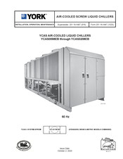
York YCAS0158EB Installation Operation & Maintenance (184 pages)
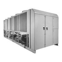
AIR-COOLED LIQUID CHILLERS
Brand:
York
| Category:
Chiller
| Size: 9.51 MB
Table of Contents
Table of Contents
4
Section 1 General Chiller Information & Safety
8
Introduction
8
Warranty
8
Safety
8
Standards for Safety
8
Responsibility for Safety
9
About this Manual
9
Misuse of Equipment
9
Suitability for Application
9
Structural Support
9
Mechanical Strength
9
General Access
9
Pressure Systems
9
Electrical
9
Rotating Parts
10
Sharp Edges
10
Refrigerants and Oils
10
High Temperature and Pressure Cleaning
10
Emergency Shutdown
10
Material Safety Data
11
Section 2 Product Description
15
Introduction
15
General Description
15
Compressor
15
Evaporator
16
Condenser
16
Oil Separator/System
17
Oil Cooling
17
Capacity Control
17
Power and Control Panel
17
Microprocessor Controls
18
Motor Current Protection
18
Motor Protection Module
19
Current Overload
19
Thermal Overload
20
Current Imbalance
20
Improper Phase Sequence
20
Motor Starting
23
Keypad Controls
23
Display
23
Entry
24
Setpoints
24
Clock
24
Print
24
Program
24
Accessories and Options
24
Multiple Point Power Connection (Standard)
24
Single-Point Power Connection with Individual Circuit Protection
24
Single-Point Power Connection with Combined Circuit Protection
24
Single-Point Power Connection Without Circuit Protection
24
DX Cooler Options
25
PSIG (21 Bar) Waterside Design Working Pressure
25
Flange Accessory
25
Remote DX Cooler
25
Flow Switch Accessory
25
Star-Delta Compressor Motor Starter
25
Unit Enclosures
25
Fans
25
Sound Reduction Options
25
Vibration Isolation
25
Unit Nomenclature Nameplate Engineering Data
26
Section 3 Handling and Storage
28
Delivery and Storage
28
Inspection
28
Moving the Chiller
28
Lifting Weights
28
Unit Rigging
29
Section 4 Installation
30
Location Requirements
30
Outdoor Installations
30
Indoor Installations
30
Location Clearances
30
Installation of Vibration Isolators
31
Installation
31
Shipping Braces
31
Pipework Connection
31
General Requirements
31
Water Treatment
32
Pipework Arrangement
33
Connection Types & Sizes
33
Cooler Connections
33
Option Flanges
33
Refrigerant Relief Valve Piping
33
Ductwork Connection
33
General Requirements
33
Electrical Connection
34
Power Wiring
34
Standard Units with Multi Point Power Supply Wiring
34
Units with Single-Point Power Supply Wiring
34
115VAC Control Supply Transformer
34
Remote Emergency Stop Device
35
Control Panel Wiring
35
Volts Free Contacts
35
Chilled Liquid Pump Starter
35
Run Contact
35
Alarm Contacts
35
System Inputs
35
Flow Switch
35
Remote Run / Stop
35
Remote Print
35
Power and Control Panel Layouts (Wye-Delta Typical)
36
Option Panel Layout (Typical)
37
Logic Section Layout
38
Logic Section Layout with Control Panel Layout
39
Customer Connections
40
Section 5 Commissioning
42
Preparation
42
Preparation - Power off
42
First Time Start-Up
44
Section 6 Operation
45
General Description
45
Start-Up
45
Normal Running and Cycling
45
Shutdown
45
Section 7 Technical Data
46
Flow Rate and Pressure Drop Charts
46
Glycol Correction Factors
46
Temperature and Flows
47
Operating Limitations & Sound Power Data
51
Electrical Data
52
Multiple Point Power Supply Connection
52
Optional Single-Point Power Supply Connection and Individual System Circuit Breakers
54
Optional Single-Point Power Supply Connection with Field Supplied Circuit Protection
56
Optional Single-Point Power Supply Connection to Factory Circuit Breaker
58
Fan Data
59
Electrical Notes
60
Wiring Diagram Across-The-Line Start
62
Wiring Diagram Wye-Delta Start
66
Elementary Diagram - Wye-Delta Start
67
Connection Diagram
74
Compressor Terminal Box
75
Dimensions
80
YCAS0128EB (English)
82
Clearances
98
Weight Distribution and Isolator Mounting Positions (Alum. Fin & Black Fin Cond. Coils)
101
Installation Instructions for VMC Series AWR/AWMR and CP Restrained Mountings
108
Refrigerant Flow Diagram
109
Process and Instrumentation Diagram
110
Component Locations
111
Compressor Components
112
System Startup Checklist
118
Unit Checks
118
Panel Checks
119
Programmed Values
119
Initial Start-Up
120
Checking Subcooling and Superheat
120
Checking Economizer Superheat
121
Leak Checking
121
Chiller Control Panel Programming and Data Access Keys
122
Display and Status Information Keys
122
ON / off Rocker Switch
122
Program & Setup Keys
122
1 Introduction & Physical Description
123
1.1 General
123
1.2 Keypad & Display
123
1.3 Unit (Chiller) on / off Switch
124
1.4 Microprocessor Board
124
1.5 Ancillary Circuit Boards
124
1.6 Circuit Breakers
125
Current Transformers (C.T.)
125
1.8 Transformers
125
1.9 Motor Protection Modules
126
EMS/BAS Controls
128
Microprocessor Board Layout
130
Logic Section Layout
131
Anti-Recycle Timer
132
Anti-Coincidence Timer
132
Evaporator Pump Control
132
Compressor Heater Control
132
Evaporator Heater Control
132
Pumpdown (LLSV) Control
132
Alarms
132
Run Status (Chiller)
133
Lead / Lag Compressor Selection
133
2 Status Key: General Status Messages & Fault Warnings
134
General
134
General Status Messages
134
Unit Warnings
135
Anticipation Control Status Messages
136
Unit Fault Status Messages
137
System Fault (Safety) Status Messages
138
Printout on Fault Shutdown
141
3 Display Keys & Option Switches
142
General
142
Chilled Liquid Temps Key
142
System # Data Keys
143
Ambient Temp Key
143
Motor Current Key
144
Operating HRS / Start Counter Key
144
Options Key & Dip Switch Settings
144
Function Key
146
4 Print Keys
147
General
147
Oper Data Key
147
Operating Data - Local Display Messages
147
Operating Data - Remote Printout
148
History Key
150
Fault History Data - Local Display Messages
150
Fault History Data - Remote Printout
153
5 Entry Keys
154
General
154
Numerical Keypad
154
Enter Key
154
Cancel Key
154
Keys
154
6 Setpoints Keys & Chilled Liquid Control
155
General
155
Chilled Liquid Temperature Control
155
Local Cooling Setpoints Key
158
Remote Cooling Setpoints Key
158
7 Clock Keys
159
General
159
Set Time Key
159
Set Schedule / Holiday Key
160
Manual Override Key
161
8 Program Key
162
General
162
Program Key - User Programmable Values
162
Programming "Default" Values
166
Condenser Fan Control
167
Section 9 Maintenance
171
General Requirements
171
Daily Maintenance
171
Scheduled Maintenance
171
Chiller/Compressor Operating Log
171
General Periodic Maintenance Checks Standard Units
174
Recommended Spares
175
Recommended Compressor Oils
175
Section 11 Troubleshooting
176
Competent Persons Troubleshooting Guide
176
Sensor Calibration Charts
178
Limited Warranty Applied Systems
179
Temperature Conversion Chart
180
Advertisement
York YCAS0158EB Manual (120 pages)
Air Cooled Screw Liquid Chillers
Brand:
York
| Category:
Chiller
| Size: 3.25 MB
Table of Contents
Table of Contents
2
Introduction
3
Specifications
4
Accessories and Options
8
Temperatures and Flows
11
Water Pressure Drop
12
Ratings
16
Physical Data
34
Dimensions
38
Operating Weights (Aluminum Fin Coils)
82
Isolator Selection (Aluminum Fin Coils)
83
Operating Weights
85
Isolator Selection
86
Isolator Selection
89
Isolator Details
92
Electrical Data
94
Electrical Notes
105
Power Connection Options
106
Typical Control Wiring
110
Application Data
112
Guide Specifications
113
Advertisement
Related Products
York YCAS0150
York Millennium YCAS0150EC
York YCAS0140
York YCAS0180
York Millennium YCAS0130EC
York Millennium YCAS0160EC
York Millennium YCAS0170EC
York Millennium YCAS0100EC
York Millennium YCAS0120EC
York YCAS0118EB
York Categories
Air Conditioner
Heat Pump
Chiller
Furnace
Air Handlers
More York Manuals
Login
Sign In
OR
Sign in with Facebook
Sign in with Google
Upload manual
Upload from disk
Upload from URL