Sign In
Upload
Manuals
Brands
Trane Manuals
Air Conditioner
IntelliPak Signature SCWF-029
Trane IntelliPak Signature SCWF-029 Manuals
Manuals and User Guides for Trane IntelliPak Signature SCWF-029. We have
3
Trane IntelliPak Signature SCWF-029 manuals available for free PDF download: Installation, Owner, And Diagnostic Manual, Programming Manual
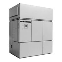
Trane IntelliPak Signature SCWF-029 Installation, Owner, And Diagnostic Manual (109 pages)
Commercial Self-Contained Signature Series, 20-80 Ton, “BO” and later Design Sequence
Brand:
Trane
| Category:
Air Conditioner
| Size: 1.79 MB
Table of Contents
About this Manual
2
Common HVAC Acronyms
2
General Information
2
Literature Change History
2
Warnings and Cautions
2
Table of Contents
3
Installation
4
General Information
4
Signature Series Self-Contained Unit Components
4
Human Interface Panel
5
Optional Controls
5
Standard Controls
5
Unit Control Module
5
Unit Nameplate
5
Model Number Description
6
Sample Unit Model Number
6
Self-Contained Ship-With Accessory Model Number Description
7
“After-Shipment” Accessory Model Number
8
Pre-Installation Considerations
9
Receiving and Handling
9
Receiving Checklist
9
Ship-Separate Accessories
9
Shipping Package
9
I-PC-1. Service and Code Clearance Requirements
10
Service Access
10
Rigging and Handling
11
Unit Handling Procedure
11
Unit Shipping
11
Pre-Installation Checklist
12
Skid Removal
12
Unit Weights - SCWF/SCRF/SIWF/SIRF
13
Variable Frequency Drive Weights
13
Electrical Connections
17
Hot Water Coil
18
Steam Coil
18
Flexible Horizontal Discharge Plenum
19
Airside Economizer
20
Dimensions and Weights
21
Duct Connection Recommendations
22
Duct Connections
22
Mechanical Requirements
22
Condensate Drain Connections
23
Condenser Connections
23
Water Piping
23
Waterside Piping Arrangements
23
Condenser Water Piping Components for Cooling Tower System
24
Installation Requirements
24
Typical Water Piping for City or Well Water System
24
Water Temperature Requirements
24
Brazing Procedures
25
Leak Test
25
Refrigerant Piping
25
Electrical Requirements
26
Supply Power Wiring
26
Unit Wiring Diagrams
26
Voltage Imbalance
26
Voltage Range
26
Fan Without VFD Data
27
Number of Compressors Per Unit
27
SCWF/SIWF Compressor Electrical Data
27
Selection Procedures
27
Compressor Isolators
28
Pre-Startup Procedures
28
Pre-Startup Requirements
28
Supply Fan Isolators
28
Unit Protective Covers
28
Optional Spring-Flex Vibration Isolator (Type CP-1) for Unit Isolation
29
Unit Isolator Installation Procedure
29
Unit Vibration Isolator Option
29
Correct Plenum Insulation Placement
30
Plenum
30
Hydronic Coil Installation
31
Steam and Hot Water Coil
31
Airside Economizer Installation
32
Field Wiring Connections
32
Unit Handling
32
Unit Preparation
32
Installing the Transducer
33
Static Pressure Sensor Installation
33
Static Pressure Transducer Installation (VAV Units Only)
33
Transducer Location
33
BAYSENS008 Description
34
BAYSENS017B Description
34
BAYSENS021 Description
34
Zone Sensor Options
34
BAYSENS013 Description
35
CV and VAV Unit Zone Sensor Options
35
CV Unit Zone Sensor Option
35
Mounting Location
36
Mounting the Subbase
36
Wiring
36
Zone Sensor Installation
36
Typical Zone Sensor Installation
37
Zone Sensor Mounting Hole Locations
37
Constant Volume Zone Sensor
38
Programmable Zone Sensors
38
Variable Air Volume Zone Sensor
38
Programmable Zone Sensor Installation
39
Surface Mounting Inside Panel
40
Time Clock Installation
40
Time Clock Option
40
Wiring Thetimeclock
40
Human Interface (HI) Panel
41
Location Recommendations
41
Remote Human Interface Panel
41
Remote Human Interface Panel Installation
41
Mounting the Remote Human Interface (RHI) Panel
42
Wall Mounting the RHI Panel
42
Remote HI Mounting Holes and Knockout Locations
43
Communication Link (Shielded Twisted Pair) Wiring
44
Interprocessor Communication Bridge Module Wiring
44
Low Voltage (AC) Field Wiring Connections
44
Wiring the Remote Human Interface
44
Communication Wiring
45
Connecting to Tracer Summit
45
Pre-Startup Checklist
46
Unit Location
46
Unit Mounting
46
Water-Cooled Unit Piping
46
BAYSENS019 Keypad and Display Configuration
47
BAYSENS019 Keypad and Display Explanation
47
Programmable Zone Sensor Options
47
Programming
47
BAYSENS020 Keypad and Display Explanation
48
Initial Power-Up
49
Keypad Operation
49
Program Button
49
Time and Day Settings
49
Keypad Lockout
50
Mode Button
50
Temporary Manual Override
50
Up and down Button Arrows
50
Keypad Operation for Temporary
51
Manual Override Menu
51
Temporary Manual Override Run Mode
51
Temporary Override Run Mode
51
Option Menu and Keypad Operation
52
Typical Option Menu Screen
52
Zone Sensor BAYSENS019 Option Menu Settings
52
Intelligent Copy
53
Remote Panel Indicator Signals from UCM to ZSM
53
To Use Intelligent Copy
53
Zone Sensor BAYSENS020 Option Menu Settings
53
BAYSENS019 Icon Descriptions
54
Icon Descriptions
54
BAYSEN020 Icon Descriptions
55
Manual Override
56
Programming the Time Clock Option
56
Setting the Time
56
To Review and Change Programs
56
Startup
57
Unit Start-Up
57
Unit Start-Up Procedures
57
Points List
60
Owner
60
General Information
60
Unit Control Components
61
RTM Module Board - Standard on All Units
61
RTM Analog Outputs
61
RTM Binary Outputs
61
Occupied/Unoccupied Contacts
62
Emergency Stop Input
62
VAV Box Option
62
Supply Duct Static Pressure Control
62
Owner Information
62
Compressor Module
63
Waterside Module - Standard on All Water-Cooled Units
63
Human Interface Module
63
Heat Module
63
Trane Communications Interface (TCI ) Module
64
Exhaust/Comparative Enthalpy (ECEM ) Module
64
Ventilation Control Module
64
Generic Building Automation System Module Option
65
GBAS Analog Inputs
65
GBAS Binary Outputs
65
GBAS Binary Input
65
GBAS Analog Input Setpoint
66
GBAS Input Voltage Corresponding Setpoints
66
Waterside Components
67
Water Purge
67
Water Piping Options
67
Waterside Economizer Option
67
Variable Water Flow
68
Basic Water Piping, Constant Water Flow
68
Intermediate Water Piping, Variable Water Flow
68
Unit Airside Components
69
Supply Air Fan
69
Low Entering Air Temperature Sensor
69
Inlet Guide Vane Option
69
Comparative Enthalpy Control
70
Airside Economizers with Traq Damper
70
Standard Two-Position Damper Interface
70
Airside Economizer Interface
70
Airside Economizer Interface with Comparative Enthalpy
71
Air-Cooled Condensers
71
Remote Air-Cooled Condenser Refrigerant Connection Sizes
71
Input Devices and System Functions
72
Compressor Circuit Breakers
72
Low Pressure Control
72
Head Pressure Control
72
Low Ambient Control
73
Low Ambient Compressor Lockout
73
Return Air Temperature Sensor
73
Supply Airflow Proving Switches
73
Control Sequences of Operation
74
Occupied/Unoccupied Switching
74
Unoccupied Sequence of Operation
74
Factory Mounted Time Clock
74
Morning Warmup
75
Full Capacity Morning Warmup (MWU)
75
Cycling Capacity Morning Warmup
75
VAV Drive Max Output
75
Occupied Sequence of Operation
76
Zone Temperature Control
76
Supply Air Temperature Control
76
Units with Economizer
76
Mechanical Cooling
77
Water-Cooled Units Only
77
Auto Changeover (Units with Heat Only)
77
Reset Based on Outdoor Air Temperature
77
Compressors
78
Compressor Cycling
78
Compressor Lead/Lag Operation
78
Compressor Stages
78
Compressor Safety Devices
79
Step Control
79
Cooling Capacity Percent
79
Service Valve Option
80
Typical Pulldown Curve for Unit Operating Properly Within Control Band
80
Maintenance Procedures
81
Air Filters
81
Without Hot Water or Steam Coil
81
With Hot Water or Steam Coil
81
Inspecting and Cleaning the Drain Pan
82
Inspecting and Cleaning the Fan
82
Supply Fan
83
Fan Drive
83
Fan Shaft and Motor Sheave Alignment
83
Fan Bearings
84
Fan Belt Tension
84
Measuring Belt Tension
84
Fan Belt Adjustment
84
Adjusting Belt Tension
85
Belt Tensioning with Fan Adjustment Points
85
Right Side View of the Self-Contained Unit
85
Refrigerant System
86
Special Note on Refrigerant Emissions
86
Refrigerant Evacuation
87
Refrigerant Charging
87
Typical Water-Cooled (SXWF) Compressor Section Components
89
Inlet Guide Vanes
90
Proper Adjustment of Inlet Guide Vanes
90
Coil Fin Cleaning
91
Steam and Hot Water Coils
91
Inspecting and Cleaning Coils
91
Refrigerant Coils
91
Cleaning the Condenser
92
Mechanical Cleaning of Condenser and Economizer Coils
92
Chemical Cleaning of Condenser and Economizer Coil
92
Piping Components
93
Water Valves
93
Flow Switch Maintenance
93
Cleaning the Flow Switch
93
Maintenance Periodic Checklists
94
Monthly Checklist
94
Semi-Annual Maintenance
94
Annual Maintenance
94
Diagnostic Troubleshooting
95
System Checks
95
Auto Reset S/A Static Pressure Limit
96
CO2 Sensor Failure
96
Compressor Trip - Ckt 1, 2, 3, or 4
96
Diagnostics
96
Dirty Filter
96
Emergency Stop
97
Entering Cond Water Temp Sensor Fail
97
Entering Water Temp Sensor Fail
97
Heat Failure
97
Heat Module Comm Failure
98
Low Air Temp Limit Trip
98
Manual Reset SA Static Press Limit
98
Mode Input Failure
98
NSB Panel Comm Failure
99
O/A Humidity Sensor Failure
99
O/A Temp. Sensor Failure
99
Return Air Temp Sensor Failure
99
RTM Aux. Temp. Sensor Failure
100
RTM Data Storage Error
100
RTM Zone Sensor Failure
100
Space Static Press Setpt Failure
100
Supply Air Temp Cool Setpoint Fail
101
Supply Air Temp Heat Setpoint Fail
101
Supply Air Temperature Failure
101
Supply Fan Failure
101
Unoccupied Zone Cool Setpoint Failure
102
Unoccupied Zone Heat Setpoint Failure
102
VCM Communication Failure
102
VOM Communications Failure
102
Water Flow Fail
103
WSM Mixed Air Temp Sensor Fail
103
Zone Cool Setpoint Failure
103
Index
104
Advertisement
Trane IntelliPak Signature SCWF-029 Programming Manual (80 pages)
Commercial Self-Contained Signature Series, 20-80 Ton Modular Series, 20-35 Ton, “AO” and later Design Sequence
Brand:
Trane
| Category:
Air Conditioner
| Size: 0.48 MB
Table of Contents
About this Manual
2
Literature Change History
2
Table of Contents
3
Intellipak ® Self-Contained Installation
3
Owner, and Diagnostic Manual SCXF
3
Programming
4
General Information
4
Ucm Control System
7
Programming the Unit
9
Data Manipulation Keys
10
Factory Presets
13
Password Protected Screens
16
STATUS Menu
17
SETUP Menu
32
SETPOINT Menu
57
CONFIGURATION Menu
63
SERVICE MODE Menu
68
DIAGNOSTICS Menu
72
Failure Modes
75
Index
76
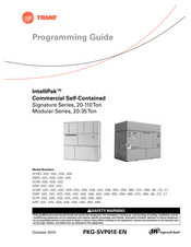
Trane IntelliPak Signature SCWF-029 Programming Manual (52 pages)
Commercial Self-Contained, 20/35-110Ton
Brand:
Trane
| Category:
Industrial Equipment
| Size: 1.3 MB
Table of Contents
Warnings, Cautions and Notices
2
Introduction
2
Overview
2
Revision History
2
Trademarks
2
Table of Contents
3
General Information
4
Commonly Used Acronyms
4
Glossary of Terms
5
Intellipak ™ Points List
5
UCM Control System
5
Programming the Unit
8
Data Manipulation Keys
9
Unit Operation Keys
10
Factory Presets
11
Password Protected Screens
13
Programming Status
14
STATUS Menu
14
Programming SETUP
22
SETUP Menu
22
SETUP Menu Screens
22
Sensor Source Selections Submenu
26
Outside Air Ventilation Setup
27
Ventilation Override Definitions
28
GBAS Module I/O Assignments
29
RTM Alarm Output Diagnostic Assignment Screens
30
Temperature Input Calibration
30
Device Charatcteristic Setup Definitions
32
Control Algorithm Tuning Parameters
35
SETPOINT Menu
36
Programming Configuration
40
SERVICE MODE Menu
43
DIAGNOSTICS Menu
45
Failure Modes
47
Diagnostics Types
47
Glossary
48
Index
50
Advertisement
Advertisement
Related Products
Trane IntelliPak Signature SCWF-020
Trane IntelliPak Signature SCWF-022
Trane IntelliPak Signature SCWF-025
Trane IntelliPak Signature SCWF-032
Trane IntelliPak Signature SCWF-035
Trane IntelliPak Signature SCWF-058
Trane IntelliPak Signature SCWF-072
Trane IntelliPak Signature SCWF-080
Trane IntelliPak Signature SCWF-065
Trane IntelliPak Signature SCWF-052
Trane Categories
Air Conditioner
Heat Pump
Chiller
Air Handlers
Furnace
More Trane Manuals
Login
Sign In
OR
Sign in with Facebook
Sign in with Google
Upload manual
Upload from disk
Upload from URL