Sign In
Upload
Manuals
Brands
Teledyne Manuals
Laboratory Equipment
4700
Teledyne 4700 Manuals
Manuals and User Guides for Teledyne 4700. We have
3
Teledyne 4700 manuals available for free PDF download: Serivce Manual, Installation And Operation Manual, Pocket Manual
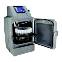
Teledyne 4700 Serivce Manual (172 pages)
Refrigerated Sampler
Brand:
Teledyne
| Category:
Laboratory Equipment
| Size: 8.39 MB
Table of Contents
Service Guide
1
Table of Contents
7
Section 1 Introduction and General Guidelines
13
About this Manual
13
Technical Specifications
14
Connection to Other Devices
16
General Maintenance
17
Pump
17
Pump Tube Replacement
19
Cleaning the Pump Rollers
21
Cleaning the Pump Housing
21
Refrigerator Cleaning Guidelines
22
Wetted Parts
22
Software
23
Updating the Software
23
Software Reset
23
System Ids
24
Safety Precautions
25
Major Assembly Removal and Replacement
26
Module Reassembly
26
Accessing the Rear Components
27
Self-Tapping Screws: Reinstallation
27
Closing the Rear Compartment
28
Rear View with Module Removed (Adhesive Strips, Permagum Sealant, Power Cables)
29
Rear View of Refrigeration Module (Adhesive Strip, Permagum Sealant)
29
Section 2 Sample Delivery System
31
Pump
31
Pump Module Replacement
32
Pump Module Replacement
33
Pump Disassembly and Parts Replacement
34
Pump Part Numbers
34
Pump Parts List
34
Thumb Screw
36
Pump Housing Cover and Band
36
Thumb Screw Removal
36
Opening the Pump Housing Cover and Latch
36
Top Cover Bushing
37
Pump Band Removal
37
Optical Disk & Sensor
38
Pump Band Latch
38
Recent Changes to the Pump
39
Old and New Mounting Plate (Idler Gear on Opposite Side)
40
Pump Motor and Wiring
41
Motor Replacement
42
Motor Plate: Mounting Holes
42
Rotor
43
Pump Motor Wiring Harness
43
Pump Rotor and Hardware
43
Gasket
44
Detector Protective Barrier
45
Pump Cover Assembly
46
Aligning the Cover
47
Aligning the Latch Keeper
48
Optional Heater
49
Installation
49
Install Heat Shield Inside Cover
50
Cut a Notch in the Top Cover for the AC Line Cord
50
Install Heater under Pump
51
Install Line Cord Clip
51
Distributor
52
Distributor Alignment
52
Distributor Module Replacement
53
Distributor Arm (A) and Discharge Tube (B)
53
Distributor Module Removal
53
Disassembling the Distributor
54
Removal of Stepper Motor and Optical Sensor
55
Rebuilding the Distributor
56
Gasket
56
Distributor Shaft
57
Belt and Motor
57
Installing the Cover Plate
58
Improperly Positioned Timing Belt
58
Distributor Part Numbers
59
Optical Sensor
59
Installing the Optical Sensor
59
Distributor Parts List
59
Overview
61
Tools
61
Parts
61
Section 3 Refrigeration System
61
Replacement Parts for 4700 Refrigerator
61
Door
62
Temperature Sensors
62
Refrigeration Temperature Sensors
62
Location of Temperature Sensors (Reverse View of Module)
63
Temperature Sensor Cable Wiring Connector
64
Control Panel Module Removal
64
Temperature Sensor Wiring Entry at Rear of Cabinet
65
Temperature Sensor Cable and Bulkhead Connector
65
(Seen from Rear with Power Supply Removed)
66
CPU Temperature Sensor
67
Sample Compartment Thermometer (Optional)
67
Refrigeration Module
68
Inspection, Troubleshooting, and Servicing
68
Temperature Verification with the 24-Bottle Rack
68
Refrigeration Service Ports
69
Piercing Service Port .312 O.D. Tubing with a Saddle Tap Tool
70
Refrigeration System Troubleshooting
71
Refrigerant Dryer, before Installation and Coating
72
Refrigerant
73
Refrigeration Module Components
73
(Possible Leak Areas Indicated by Arrows)
73
Refrigeration Charging
75
Condenser Fan
76
Removal/Replacement of Condenser Fan
77
Condenser Fan Connections
77
Module Replacement
78
Removing 230V Adaptor from AC Power Cord
78
Remove Power Cord
79
Electrical Connections on 100V/120V Compressors
79
Electrical Connections on 230V Compressors
80
Refrigeration Cool down Test
82
Section 4 CPU and Power Supply
83
4700 CPU Circuit Board Description
83
Processor - U28
83
Memory - U26, 27
84
I/O Ports - U11, 14
84
Serial Port - U32
85
Flow Meter Interface - U6, 17, P2
85
Liquid Detector - U3, 10, P7
85
Temperature Inputs - U16, P5
85
Microprocessor Supervision - U23
85
Distributor Motor Drive - U1, P1/Rotation Sensor - P4, U9
86
Lcd - U29, 31, 33, 34, 35, 36, J1
86
Pump Drive - U17, 18, 19, 20, 21, 22, Q1-8, P9, P10, P8
86
Case Heater - U25
87
General Outputs - U4, 5, P3
87
Analog Input - U7, 8, 17, 30, P3
87
Vref - U2
87
Test Points
88
Test Point Functions and Values
88
CPU Board Tests
89
Sampling Reports
89
Functional Tests
89
CPU Board Functional Tests
90
Control Panel
93
Control Panel Removal
93
Control Panel Installation
94
Control Panel Module Removal/Replacement
94
Control Panel Connector Identification and Wiring
95
Power Backup
96
Power Supply
97
Recent Changes to the Power Supply
97
Fuse
98
Power Supply Removal
99
Remove Power Cord
100
Electrical Connections on 100V/120V Compressors
100
Power Supply Replacement
103
Line Cord
104
Line Cord Removal
104
Line Cord Replacement
106
Section 5 Electrical Troubleshooting and Diagnostics
109
4700 Diagnostics
109
Test 'RAM
110
Test 'ROM
110
Test Display
110
Test Keypad
111
Test Pump
111
Test Distributor
112
Distributor Arm (A), Discharge Tube (B), and Stop (C)
112
Distributor Arm Positioning, Discharge Tube Removed
113
Test Flow Meter Port
114
Refrig Temperature
114
PCB Temperature
114
Input Voltage
115
Battery Voltage
115
Loaded Battery Voltage
116
Display Analog Input
116
Hidden Menu Functions
117
Compressor and Compartment Heater
117
Compressor Control
118
Fan Control
120
Diag Menu
120
Diagnostic Data
120
Test Time/Date
120
Pump Information
121
Duty Cycle
121
Language
121
Enabling Spas
121
Nonstandard Bottle Setup
121
Appendix A Electrical Diagrams
123
Appendix B Replacement Parts List
129
Sampler/Refrigerator Replacement Parts
130
Bottle Configuration Replacement Parts
160
Advertisement
Teledyne 4700 Installation And Operation Manual (137 pages)
Refrigerated Samplers
Brand:
Teledyne
| Category:
Samplers
| Size: 9.74 MB
Table of Contents
Table of Contents
4
Tab 4
5
Section 1 Introduction
15
Sampler Overview
15
Features
16
Specifications
18
Section 2 Installation
20
Unpacking the Sampler
20
4700 Sampler Installation Overview
20
Positioning the Sampler
20
Minimum Space Requirements
22
Installing a Bottle Kit
23
Installing the Distributor Arm and Discharge Tube
24
Installing the Distributor Arm (A) and Discharge Tube (B)
24
Insert the Keyed End First so that It Faces the Back of the Refrigerated Compartment
26
The 24-Bottle Rack Is Held in Place by a Latch on the Left Side
26
Bottles
27
Installing the Locating Base
27
Bottle
28
Attaching the Suction Line
29
One 20 Liter Bottle Configuration with Discharge Tube through the Bottle Cap
29
Vinyl Suction Line
30
FEP-Lined Suction Line
31
Releasing a Tube Coupler Clamp
31
Connecting FEP-Lined Suction Line (A) to Pump Tube (B)
31
Attaching a Strainer
32
Alternative to Strainers
33
Maximum Unanchored Depth
33
Routing the Suction Line and Strainer
33
Connecting the Sampler to External Devices
33
Standard Isco Instrument Connections
34
External Device Connection at Rear of Sampler
34
Other Device Connections
35
Quick Disconnect Box 60-2004-228
35
Unterminated Connect Cable
36
Connecting Power
37
Configuring and Programming the Sampler
37
Locking the Sampler
37
Section 3 Programming
38
Control Panel Description
38
Control Panel Buttons
38
Control Buttons
38
Getting Started
39
Configuring the Sampler
40
Set Clock
40
Bottle and Sizes
41
Suction Line
41
Suction Line Length
41
Liquid Detector
42
Flow Mode Sampling
42
Enable Pin
42
Refrigeration
43
Output Pins
43
Tubing Life
44
Program Lock
45
Language
46
System Ids
46
Run Diagnostics
46
Exit Configuration
46
Sampling Program Overview
47
Time Paced Sampling Program Flow Chart
48
Time Paced Sampling Program
48
Flow Paced Sampling Program Flow Chart
49
Flow Paced Sampling Program
49
Programming Steps
50
Pacing
50
Sample Every
50
Flow Pulse Intervals at Various Input Currents
51
Bottles Per Sample Event
53
Switch on Time or Number of Samples
53
Switch Bottles Every_ Hours
53
First Switch Time
53
Run Continuously
54
Enter Sample Volume Use Defined Sample
54
Volumes Dependent on Flow
55
Sample Volume
55
Flow Pulses, Analog Input
55
Ml for Every
55
Sample Volume at 20 Ma
55
Suction Head
56
No Delay to Startset Start Time
56
Suction Head Height
56
First Sample at
57
Start Flow Count at
57
Maximum Run Time Hours
57
Programming Examples
57
Defining the Sample Volume
57
Section 4 Operation
63
Start a Sampler Program
63
Start Time Delay
63
The Run State
64
Completed Program
64
Pause or Stop a Running Program
65
Post Sampling Activities
65
View the Log
65
Retrieve the Temperature Log
67
Sample Temperature Report
68
Remove Sample Bottles
69
Sliding the 24-Bottle Rack out
69
Grab Samples
70
Calibrate Sample Volumes
70
Operate the Pump Manually
71
Section 5 Maintenance
72
Periodic Maintenance Checklist
72
Pump Inspection
72
Pump Tube Replacement
74
Rollers (A) and Guides (B) on the Pump Rotor
74
Cleaning the Pump Rollers
76
Cleaning the Pump Housing
76
Cleaning or Replacing Wetted Parts
76
Sampler Cleaning Guidelines
77
Sampler Diagnostics
77
Wetted Parts
77
Test 'RAM
78
Test 'ROM
78
Test Display
79
Test Keypad
79
Test Pump
79
Test Distributor
80
Test Flow Meter Port
81
Refrig Temperature
81
PCB Temperature
81
Input Voltage
82
Battery Voltage
82
Loaded Battery Volts
82
Temperature Verification
84
Temperature Verification with the 24-Bottle Rack
84
Temperature Verification with the Bottle Locating Base
84
Major Assembly Removal and Replacement
85
General Instructions
85
Pump Module
85
Pump Module Replacement
87
Control Panel Module
88
Control Panel Wiring Connectors
89
Distributor Module
90
Distributor Module Replacement
90
Refrigeration Module
91
Remove Back Cover and Insulation
91
Remove Refrigeration Module
92
Remove Power Cord
92
Electrical Connections on 230V Compressors
93
Appendix A Replacement Parts
96
Appendix B General Safety Procedures
123
Hazards
123
Planning
124
Adverse Atmospheres
124
Entering Manholes
124
Traffic Protection
125
Removing the Covers
125
Other Precautions
125
Emergencies
126
Field Equipment
126
Lethal Atmospheres in Sewers
126
Hazardous Gases
128
Specifications
131
Bottle Kits
131
Strainers
134
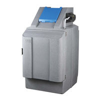
Teledyne 4700 Pocket Manual (128 pages)
Refrigerated Sampler
Brand:
Teledyne
| Category:
Laboratory Equipment
| Size: 0.64 MB
Table of Contents
Table of Contents
3
1 Introduction
7
Features
7
Specifications
12
2 Installation
12
4700 Sampler Installation Overview
17
Positioning the Sampler
17
Installing a Bottle Kit
21
Installing the Distributor Arm and Discharge Tube
24
Bottles
26
Bottles
28
Bottle
30
Attaching the Suction Line
32
Vinyl Suction Line
33
FEP-Lined Suction Line
35
Attaching a Strainer
35
Alternative to Strainers
38
Maximum Unanchored
38
Depth
38
Routing the Suction Line and Strainer
39
Connecting the Sampler to External Devices
39
Standard Isco Instrument Connections
41
Other Device Connections
41
Connecting Power
46
Configuring and Programming the Sampler
47
Locking the Sampler
47
3 Programming
49
Control Panel Description
49
Getting Started
51
Configuring the Sampler
52
Set Clock
53
Bottle and Sizes
53
Suction Line
54
Liquid Detector
55
Flow Mode Sampling
57
Enable Pin
58
Refrigeration
59
Output Pins
60
Tubing Life
62
Program Lock
64
Language
65
System Ids
66
Run Diagnostics
67
Exit Configuration
67
Sampling Program Overview
67
Programming Steps
74
Pacing
74
Sample Every
75
Minutes
75
Bottles Per Sample Event
79
First Switch Time
80
Of Samples
80
Switch Bottles Every
80
Switch on Time or Number
80
Run Continuously
82
Enter Sample Volume Use Defined Sample
82
Volumes Dependent on Flow
83
Sample Volume
84
Flow Pulses, Analog Input
84
Ml for Every
84
Sample Volume at 20 Ma
85
Composite Samples
85
Suction Head
86
No Delay to Start Set Start Time
87
First Sample at
88
Start Flow Count at
88
Maximum Run Time
88
Programming Examples
89
Defining the Sample Volume
89
Time Paced Sampling Program
92
Flow Paced Sampling Program
95
Flow-Proportional Constant Time Variable Volume Program
99
4 Operation
103
Start a Sampler Program
103
Start Time Delay
104
The Run State
105
Completed Program
106
Pause or Stop a Running Program
106
Post Sampling Activities
107
View the Log
107
Remove Sample Bottles
112
Grab Samples
113
Calibrate Sample Volumes
114
Operate the Pump Manually
117
5 Maintenance
119
Periodic Maintenance Checklist
119
Pump Inspection
120
Pump Tube Replacement
122
Cleaning the Pump Rollers
125
Cleaning the Pump Housing
125
Cleaning or Replacing Wetted Parts
125
Sampler Cleaning Guidelines
127
Advertisement
Advertisement
Related Products
Teledyne 402R-EU
Teledyne 4020
Teledyne 4040
Teledyne 4060 Series
Teledyne Linea GigE 4k
Teledyne 465M
Teledyne HASTINGS 4/6
Teledyne 440
Teledyne PINNACLE 45
Teledyne 400E
Teledyne Categories
Measuring Instruments
Analytical Instruments
Digital Camera
Test Equipment
Laboratory Equipment
More Teledyne Manuals
Login
Sign In
OR
Sign in with Facebook
Sign in with Google
Upload manual
Upload from disk
Upload from URL